EP1057994A2 - Method and apparatus for controlling fuel injection in diesel engine - Google Patents
Method and apparatus for controlling fuel injection in diesel engine Download PDFInfo
- Publication number
- EP1057994A2 EP1057994A2 EP00111710A EP00111710A EP1057994A2 EP 1057994 A2 EP1057994 A2 EP 1057994A2 EP 00111710 A EP00111710 A EP 00111710A EP 00111710 A EP00111710 A EP 00111710A EP 1057994 A2 EP1057994 A2 EP 1057994A2
- Authority
- EP
- European Patent Office
- Prior art keywords
- fuel injection
- revolution speed
- amount
- engine revolution
- engine
- Prior art date
- Legal status (The legal status is an assumption and is not a legal conclusion. Google has not performed a legal analysis and makes no representation as to the accuracy of the status listed.)
- Granted
Links
Images

Classifications
-
- F—MECHANICAL ENGINEERING; LIGHTING; HEATING; WEAPONS; BLASTING
- F02—COMBUSTION ENGINES; HOT-GAS OR COMBUSTION-PRODUCT ENGINE PLANTS
- F02D—CONTROLLING COMBUSTION ENGINES
- F02D41/00—Electrical control of supply of combustible mixture or its constituents
- F02D41/02—Circuit arrangements for generating control signals
- F02D41/021—Introducing corrections for particular conditions exterior to the engine
- F02D41/0215—Introducing corrections for particular conditions exterior to the engine in relation with elements of the transmission
- F02D41/023—Introducing corrections for particular conditions exterior to the engine in relation with elements of the transmission in relation with the gear ratio shifting
-
- F—MECHANICAL ENGINEERING; LIGHTING; HEATING; WEAPONS; BLASTING
- F02—COMBUSTION ENGINES; HOT-GAS OR COMBUSTION-PRODUCT ENGINE PLANTS
- F02D—CONTROLLING COMBUSTION ENGINES
- F02D41/00—Electrical control of supply of combustible mixture or its constituents
- F02D41/02—Circuit arrangements for generating control signals
- F02D41/14—Introducing closed-loop corrections
- F02D41/1497—With detection of the mechanical response of the engine
- F02D41/1498—With detection of the mechanical response of the engine measuring engine roughness
-
- F—MECHANICAL ENGINEERING; LIGHTING; HEATING; WEAPONS; BLASTING
- F02—COMBUSTION ENGINES; HOT-GAS OR COMBUSTION-PRODUCT ENGINE PLANTS
- F02D—CONTROLLING COMBUSTION ENGINES
- F02D41/00—Electrical control of supply of combustible mixture or its constituents
- F02D41/30—Controlling fuel injection
- F02D41/38—Controlling fuel injection of the high pressure type
- F02D41/40—Controlling fuel injection of the high pressure type with means for controlling injection timing or duration
-
- F—MECHANICAL ENGINEERING; LIGHTING; HEATING; WEAPONS; BLASTING
- F02—COMBUSTION ENGINES; HOT-GAS OR COMBUSTION-PRODUCT ENGINE PLANTS
- F02D—CONTROLLING COMBUSTION ENGINES
- F02D2200/00—Input parameters for engine control
- F02D2200/02—Input parameters for engine control the parameters being related to the engine
- F02D2200/10—Parameters related to the engine output, e.g. engine torque or engine speed
- F02D2200/1015—Engines misfires
-
- F—MECHANICAL ENGINEERING; LIGHTING; HEATING; WEAPONS; BLASTING
- F02—COMBUSTION ENGINES; HOT-GAS OR COMBUSTION-PRODUCT ENGINE PLANTS
- F02D—CONTROLLING COMBUSTION ENGINES
- F02D41/00—Electrical control of supply of combustible mixture or its constituents
- F02D41/02—Circuit arrangements for generating control signals
- F02D41/021—Introducing corrections for particular conditions exterior to the engine
- F02D41/0215—Introducing corrections for particular conditions exterior to the engine in relation with elements of the transmission
- F02D41/022—Introducing corrections for particular conditions exterior to the engine in relation with elements of the transmission in relation with the clutch status
-
- Y—GENERAL TAGGING OF NEW TECHNOLOGICAL DEVELOPMENTS; GENERAL TAGGING OF CROSS-SECTIONAL TECHNOLOGIES SPANNING OVER SEVERAL SECTIONS OF THE IPC; TECHNICAL SUBJECTS COVERED BY FORMER USPC CROSS-REFERENCE ART COLLECTIONS [XRACs] AND DIGESTS
- Y02—TECHNOLOGIES OR APPLICATIONS FOR MITIGATION OR ADAPTATION AGAINST CLIMATE CHANGE
- Y02T—CLIMATE CHANGE MITIGATION TECHNOLOGIES RELATED TO TRANSPORTATION
- Y02T10/00—Road transport of goods or passengers
- Y02T10/10—Internal combustion engine [ICE] based vehicles
- Y02T10/40—Engine management systems
Definitions
- the present invention relates to a method and apparatus for controlling an amount of fuel to be injected into a diesel engine, and more particularly to a method and apparatus that can reduce shock upon clutch engagement while an engine brake is applying.
- a basic amount of fuel injection in a diesel engine is determined based on an engine revolution speed and an accelerator opening, and this basic value is modified based on temperature of water flowing in the engine and/or intake air temperature in order to determine an ultimate (or target) amount of fuel injection.
- An object of the present invention is to overcome the above described problems.
- an arrangement for controlling fuel injection in a diesel engine including a sensor for detecting if an engine revolution speed change per unit time exceeds a predetermined amount, another sensor for detecting if an accelerator opening stays within a predetermined range, and a controller for determining a target amount of fuel injection that is greater than a basic amount of fuel injection when the engine revolution speed change exceeds the predetermined amount and the accelerator opening stays in the predetermined range.
- the basic amount of fuel injection is determined at least based on the accelerator opening and engine revolution speed.
- the engine revolution speed change sensor may determine whether the engine revolution speed variation exceeds the predetermined value by comparing a filtered value of engine revolution speed change rate with a threshold value that changes with the engine revolution speed.
- the controller may determine the target amount of fuel injection based on at least one of the engine revolution speed and the temperature of water flowing in the engine.
- a fuel injection system in a diesel engine mounted in a vehicle equipped with a manual transmission The vehicle also has a manual clutch of friction type, which is disengaged and engaged as a driver stamps and releases a clutch pedal.
- a diesel engine 1 has at least one fuel injection nozzle 2 for injecting fuel into an associated combustion chamber. For the sake of simplicity, the following description only deals with the fuel injection nozzle 2 illustrated.
- the fuel injection nozzle 2 is supplied with pressurized fuel from a fuel injection pump 3 via a pipe 4.
- the fuel pump 3 is a distribution-type in this particular embodiment.
- An amount of fuel delivery is determined by an electronic control unit (ECU) 5.
- the fuel pump 3 has two electromagnetic valves (not shown), which are used to determine the start of fuel delivery and the end respectively. ECU 5 switches these electromagnetic valves such that an appropriate amount of pressurized fuel is fed to the nozzle 2 at an appropriate timing.
- An intake air passage 6 extends to the engine 1 and an exhaust passage 7 extends from the engine 1.
- MAF (mass air flow) sensor 8 which serves as a sensor for detecting an amount of intake air, is provided on the intake air pipe 6 near the inlet of the intake air pipe. An output of the MAF sensor 8 is sent to ECU 5. Accordingly, the amount of intake air can be detected while the engine is operating. It should be noted here that the term "amount of intake air” is a mass flow rate of intake air in this specification. Downstream of the MAF sensor 8 on the intake air pipe 6, provided is an intake air pressure sensor 9. This sensor also outputs its detection result to ECU 5. Accordingly, the intake air pressure can be detected while the engine is running.
- the engine 1 is further equipped with a turbocharger 10.
- a compressor 11 of the turbocharger 10 is attached to the intake air pipe 6 between the MAF sensor 8 and intake air pressure sensor 9.
- a waste gate 13 is provided on the exhaust pipe 7 upstream of a turbine 12 of the turbocharger 10 to control the exhaust air to be supplied to the turbine 12.
- the waste gate 13 includes a negative pressure actuator 14 and an electromagnetic valve 15 for feeding or stopping negative pressure (upwardly directing unshaded arrow) to the actuator 14. Based on the output of the intake air pressure sensor 9, the waste gate electromagnetic valve 15 is opened or closed under the control of ECU 5. When the waste gate 13 is opened, the exhaust air from the engine 1 bypasses the turbine 12 and is expelled to the outside as indicated by the shaded arrow EXT.
- ECU 5 To ECU 5, connected are an engine revolution speed sensor 16 and an accelerator opening sensor 17. Accordingly, ECU 5 is able to detect the engine revolution speed and the accelerator opening. ECU 5 is also provided with an output from a clutch switch 20 so that it can determine whether the clutch is engaged or disengaged.
- the clutch switch 20 is turned on when the driver stamps the clutch pedal, and turned off when the driver releases the clutch pedal. If a play of the clutch pedal is neglected, the clutch is in the disengaged condition when the clutch switch 20 is on whereas it is in the engaged condition when the clutch switch is off.
- a water temperature sensor 21 is also connected to ECU 5 so that ECU 5 detects the temperature of water flowing in the engine 1.
- FIG. 5 illustrated is a timing chart of various parts, switches, values, etc.
- the engine revolution speed Ne steeply rises upon clutch engagement (at the time to). Reaction to this causes the engine revolution speed Ne to fluctuate for a while.
- This attenuating fluctuation is referred to as "shift shock", and the present invention aims to suppress this shift shock.
- the symbol Ac indicates the accelerator opening.
- a change rate ⁇ Ne of the engine revolution speed Ne is determined, and processed to a filtered value ⁇ Ne Filter .
- This value ⁇ Ne Filter is compared with a predetermined threshold value C ⁇ Ne. If ⁇ Ne Filter is greater than C ⁇ Ne, it is determined that there is a change in the engine revolution speed. If not, it is determined that there is no change in the engine revolution speed.
- t1, t2, ..., t8 indicate the moments when ECU 5 makes the detection, comparison, computation, and determination.
- ⁇ Ne 1 is smaller than C ⁇ Ne. Therefore, it is determined that there is no engine revolution speed change.
- ⁇ Ne 2 is greater than C ⁇ Ne. Thus, it is first determined at the time t2 that there is engine revolution speed change. In this case, ⁇ Ne 2 is used as the filtered value ⁇ Ne Filter .
- the engine speed change rate ⁇ Ne continuously changes so that the absolute value of ⁇ Ne becomes occasionally smaller than C ⁇ Ne even though there is engine revolution speed change, for example at the time t3. It is inconsistent to the actual phenomena if ECU 5 determines that there is no revolution speed change at such occasion. In the present invention, therefore, determination is made in the following manner once the revolution speed change is determined.
- ECU 5 at the first step 201 subtracts the previous engine revolution speed Ne(-1) from the current engine revolution speed Ne to calculate the engine revolution speed change rate ⁇ Ne (Ne - Ne(-1)).
- ECU obtains the threshold value C ⁇ Ne from a map M4 based on the current engine revolution speed Ne.
- the map M4 is prepared beforehand from experiments or theoretical computations, and stored in ECU 5.
- the threshold value C ⁇ Ne varies with the engine speed Ne; the threshold value has a low value when the engine speed Ne is high.
- step 205 compare the absolute value
- the program advances to step 208 to set the shift shock flag to be 0.
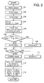
- Figure 1 illustrates a block diagram of parts and maps related to this control and Figure 2 illustrates the flowchart of the same control. In other words, Figures 1 and 2 illustrate the substantially the same thing.
- the map M1 is a three-dimensional map to determine a basic amount of fuel injection Q base .
- the basic amount of fuel injection is uniquely determined from the engine revolution speed Ne detected by the engine speed sensor 16 and the accelerator opening degree Ac detected by the accelerator sensor 17. This way of determining the basic amount of fuel injection using a map is common in the technical field of fuel injection control. Further, it is conventional to amend the basic amount of fuel injection Q base with the engine water temperature and/or intake air temperature. For the sake of simplicity, in this particular specification, however, such amendment is not performed.
- the map M2 is also a three-dimensional map to primarily determine an amount of first fuel injection Q bsh after the engine revolution speed change occurs (see the curve Q fnl in Figure 5). This amount of first injection Q bsh is uniquely determined from the engine speed Ne and the water temperature Tw detected by the water temperature sensor 21.
- the Map3 is a two-dimensional map to determine the subtraction value Q red , which is a value utilized in a subtracting calculation made to the amount of fuel injection in the revolution speed change suppression control.
- the value Q red is uniquely determined from the engine speed Ne.
- a switchover element 23 takes a value 0 (the reason will be described later) so that the amount of first fuel injection Q bsh becomes the output Q shift of the element 23. Then, the output becomes Q shiftfnl and is input to the comparator 22.
- Another input to the comparator 22 is Q base , which is smaller than Q bsh since currently the engine brake is applying and the accelerator opening degree Ac is almost zero. Accordingly, the first amount of fuel injection Q bsh , which is obtained by adding a certain value to the basic amount of fuel injection Q base and therefore greater than it, becomes the ultimate (or target) amount of fuel injection Q fnl .
- the amount of first fuel injection Q bsh is input to a second comparator 24.
- Another input to this comparator 24 is an amount of reduced fuel injection Q dmp .
- This value Q dmp is obtained by subtracting the value Q red from the previous output Q shift (-1) of the switch 23, i.e., the amount of previous first fuel injection Q bsh .
- this comparator 24 outputs the smaller one as the minimum amount of fuel injection Q min .
- Q dmp ⁇ Q bsh is established so that Q dmp becomes Q min .
- Q shiftfnl Since the subtraction value Q red is a small value, the relationship of Q shiftfnl > Q base is still established in the comparator 22.
- the target amount of fuel injection Q fnl is determined in the same manner as described above.
- the target amount of fuel injection Q fnl is gradually decreased from the starting value Q bsh as the time passes (see the curve Q fnl in Figure 5).
- the value Q fnl is still greater than the basic value Q base .
- the amount of fuel injection is slightly raised as the engine revolution speed change occurs. Therefore, the deceleration of the vehicle and its reaction are suppressed, and the engine revolution speed fluctuation and the back and forth movement of the vehicle is reduced. Consequently, the passengers in the vehicle do not experience uncomfortableness. Nevertheless, the amount of addition to the fuel injection is limited to the minimum since the engine brake is applying. The amount of first fuel injection Q bsh should be determined in view of this.
- the same fuel injection control as described above may be realized by the driver if he/she can stamp and release the accelerator pedal appropriately. In reality, however, such manual (or foot) control of the accelerator pedal requires a high skill and is complicated. Thus, it is not practical.
- the present invention provides the apparatus and method of automatically performing such control.
- ECU 5 reads the basic amount of fuel injection Q base from the map M1.
- ECU 5 also reads the amount of initial fuel injection Q bsh from the second map M2.
- ECU 5 further reads the subtraction value Q red from the third map M3.
- ECU 5 takes the smaller one of the initial value Q bsh and the reduced value Q dmp as the minimum amount of fuel injection Q min .
- the revolution speed change threshold value C ⁇ Ne varies with the engine revolution speed Ne (map M4 in Figure 3).
- this threshold value is small when the engine revolution speed Ne is high, as indicated in the map M4. This is because the higher the engine revolution speed Ne, the larger the shift shock upon clutch engagement.
- the amount of first fuel injection Q bsh is adjusted in accordance with the water temperature Tw because the minimum amount of fuel injection required for engine acceleration varies with the water temperature Tw.
- the present invention is not limited to the above described embodiments.
- the present invention is applicable to a common rail type (accumulation type) fuel injection system.
Landscapes
- Engineering & Computer Science (AREA)
- Chemical & Material Sciences (AREA)
- Combustion & Propulsion (AREA)
- Mechanical Engineering (AREA)
- General Engineering & Computer Science (AREA)
- Electrical Control Of Air Or Fuel Supplied To Internal-Combustion Engine (AREA)
- Combined Controls Of Internal Combustion Engines (AREA)
Abstract
Description
- The present invention relates to a method and apparatus for controlling an amount of fuel to be injected into a diesel engine, and more particularly to a method and apparatus that can reduce shock upon clutch engagement while an engine brake is applying.
- Conventionally, a basic amount of fuel injection in a diesel engine is determined based on an engine revolution speed and an accelerator opening, and this basic value is modified based on temperature of water flowing in the engine and/or intake air temperature in order to determine an ultimate (or target) amount of fuel injection.
- Incidentally, when a driver is operating a vehicle equipped with a manual transmission, he/she may perform a shift-down operation to the transmission (gear shift-down) while an engine brake is being applying. In this situation, the engine revolution speed often rises steeply upon engagement of a clutch. This results in great change in engine revolution speed. This is primarily caused by negative acceleration due to the engine brake and inertia of the vehicle. As the clutch is engaged, the load on the vehicle is first shifted forward and then shifted backward because of reaction. In other words, back-and-forth oscillation occurs. This results in very fast change in the engine revolution speed, as mentioned earlier. As the engine revolution speed varies rapidly, passengers in the vehicle are forced to move back and forth and experience great uncomfortableness.
- An object of the present invention is to overcome the above described problems.
- According to one embodiment of the present invention, there is provided an arrangement for controlling fuel injection in a diesel engine, including a sensor for detecting if an engine revolution speed change per unit time exceeds a predetermined amount, another sensor for detecting if an accelerator opening stays within a predetermined range, and a controller for determining a target amount of fuel injection that is greater than a basic amount of fuel injection when the engine revolution speed change exceeds the predetermined amount and the accelerator opening stays in the predetermined range. The basic amount of fuel injection is determined at least based on the accelerator opening and engine revolution speed.
- The engine revolution speed change sensor may determine whether the engine revolution speed variation exceeds the predetermined value by comparing a filtered value of engine revolution speed change rate with a threshold value that changes with the engine revolution speed.
- The controller may determine the target amount of fuel injection based on at least one of the engine revolution speed and the temperature of water flowing in the engine.
- Additional objects and advantages of the present invention will become apparent to those skilled in the art to which the invention relates from the subsequent detailed description and appended claims, taken in conjunction with the accompanying drawings.
- Figure 1
- illustrates a block diagram of various elements in an apparatus of the present invention, which is useful to explain fuel injection control according to the present invention;
- Figure 2
- illustrates a main flowchart corresponding to the block diagram shown in Figure 1;
- Figure 3
- illustrates a flowchart utilized in determining whether shift shock occurs or not according to the present invention;
- Figure 4
- illustrates timing charts used to detect engine revolution speed change according to the present invention;
- Figure 5
- is timing charts showing relationship between various values utilized in the control of the invention; and
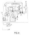
- Figure 6
- schematically illustrates an engine equipped with the apparatus of the present invention.
- Now, an embodiment of the present invention will be described in reference to the accompanying drawings.
- Referring first to Figure 6, illustrated is a fuel injection system in a diesel engine mounted in a vehicle equipped with a manual transmission. The vehicle also has a manual clutch of friction type, which is disengaged and engaged as a driver stamps and releases a clutch pedal. A
diesel engine 1 has at least onefuel injection nozzle 2 for injecting fuel into an associated combustion chamber. For the sake of simplicity, the following description only deals with thefuel injection nozzle 2 illustrated. - The
fuel injection nozzle 2 is supplied with pressurized fuel from afuel injection pump 3 via apipe 4. Thefuel pump 3 is a distribution-type in this particular embodiment. An amount of fuel delivery is determined by an electronic control unit (ECU) 5. Thefuel pump 3 has two electromagnetic valves (not shown), which are used to determine the start of fuel delivery and the end respectively.ECU 5 switches these electromagnetic valves such that an appropriate amount of pressurized fuel is fed to thenozzle 2 at an appropriate timing. - An
intake air passage 6 extends to theengine 1 and anexhaust passage 7 extends from theengine 1. MAF (mass air flow) sensor 8, which serves as a sensor for detecting an amount of intake air, is provided on theintake air pipe 6 near the inlet of the intake air pipe. An output of the MAF sensor 8 is sent toECU 5. Accordingly, the amount of intake air can be detected while the engine is operating. It should be noted here that the term "amount of intake air" is a mass flow rate of intake air in this specification. Downstream of the MAF sensor 8 on theintake air pipe 6, provided is an intake air pressure sensor 9. This sensor also outputs its detection result toECU 5. Accordingly, the intake air pressure can be detected while the engine is running. - The
engine 1 is further equipped with aturbocharger 10. Acompressor 11 of theturbocharger 10 is attached to theintake air pipe 6 between the MAF sensor 8 and intake air pressure sensor 9. Awaste gate 13 is provided on theexhaust pipe 7 upstream of aturbine 12 of theturbocharger 10 to control the exhaust air to be supplied to theturbine 12. Thewaste gate 13 includes anegative pressure actuator 14 and anelectromagnetic valve 15 for feeding or stopping negative pressure (upwardly directing unshaded arrow) to theactuator 14. Based on the output of the intake air pressure sensor 9, the waste gateelectromagnetic valve 15 is opened or closed under the control ofECU 5. When thewaste gate 13 is opened, the exhaust air from theengine 1 bypasses theturbine 12 and is expelled to the outside as indicated by the shaded arrow EXT. - To ECU 5, connected are an engine
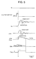
revolution speed sensor 16 and anaccelerator opening sensor 17. Accordingly, ECU 5 is able to detect the engine revolution speed and the accelerator opening. ECU 5 is also provided with an output from aclutch switch 20 so that it can determine whether the clutch is engaged or disengaged. Theclutch switch 20 is turned on when the driver stamps the clutch pedal, and turned off when the driver releases the clutch pedal. If a play of the clutch pedal is neglected, the clutch is in the disengaged condition when theclutch switch 20 is on whereas it is in the engaged condition when the clutch switch is off. A water temperature sensor 21 is also connected toECU 5 so thatECU 5 detects the temperature of water flowing in theengine 1. - Referring now to Figure 5, illustrated is a timing chart of various parts, switches, values, etc. When the driver performs a shift-down operation while the vehicle is cruising, in order to apply an engine brake, the engine revolution speed Ne steeply rises upon clutch engagement (at the time to). Reaction to this causes the engine revolution speed Ne to fluctuate for a while. This attenuating fluctuation is referred to as "shift shock", and the present invention aims to suppress this shift shock. The symbol Ac indicates the accelerator opening.
- Now, a method and apparatus for controlling the fuel injection to achieve this object will be described.
- First, detection of engine revolution speed change will be described. The outline is briefly described first. As illustrated in Figure 5, a change rate ΔNe of the engine revolution speed Ne is determined, and processed to a filtered value ΔNeFilter. This value ΔNeFilter is compared with a predetermined threshold value CΔNe. If ΔNeFilter is greater than CΔNe, it is determined that there is a change in the engine revolution speed. If not, it is determined that there is no change in the engine revolution speed. These detection, computation, comparison and determination are performed in
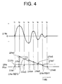
ECU 5 periodically at predetermined control intervals sinceECU 5 handles the values in a digitized manner. The engine speed change rate ΔNe is defined by the equation: ΔNe = Ne - Ne(-1). Ne represents a current engine revolution speed and Ne(-1) represents a previous engine revolution speed. The engine revolution speed Ne is detected periodically. - Next, referring to Figure 4, determination of the filtered value ΔNeFilter will be described. In this drawing, t1, t2, ..., t8 indicate the moments when
ECU 5 makes the detection, comparison, computation, and determination. - It should be assumed that the engine speed change rate ΔNe varies due to the engine revolution speed change. Absolute values ΔNe1, ΔNe2, ..., ΔNe8 of the speed change rates ΔNe at t1, t2, ..., t8 are plotted on the ΔNeFilter line.
- At the time t1, ΔNe1 is smaller than CΔNe. Therefore, it is determined that there is no engine revolution speed change. At the time t2, Δ Ne2 is greater than CΔNe. Thus, it is first determined at the time t2 that there is engine revolution speed change. In this case, ΔNe2 is used as the filtered value ΔNeFilter.
- The engine speed change rate ΔNe continuously changes so that the absolute value of ΔNe becomes occasionally smaller than CΔNe even though there is engine revolution speed change, for example at the time t3. It is inconsistent to the actual phenomena if
ECU 5 determines that there is no revolution speed change at such occasion. In the present invention, therefore, determination is made in the following manner once the revolution speed change is determined. - At the time t2, ΔNeFilter = ΔNe2 is established, and then at the next time t3, a certain value n is extracted from the previous value ΔNeFilter (= ΔNe2) to obtain a reference value ΔNeREF3; ΔNeREF3 = ΔNe2 - n. Then, ΔNeREF3 is compared with ΔNe3 to take the larger one (ΔNeREF3) as the current ΔNeFilter. In this manner, the filtered value ΔNeFilter is made greater than CΔNe, and accordingly
ECU 5 can determine that there is revolution speed change. - In a similar manner, at the following times t3, t4, ..., the value n is subtracted from ΔNeFilter each time to obtain a new reference value ΔNeREF, and it is compared with the present ΔNe. The larger one is then taken as ΔNeFilter, and compared with CΔNe. Eventually, at the time t7, both ΔNe7 and ΔNeREF7 become lower than CΔNe. At this point, it is first determined that the revolution speed change no longer exists.
- As described above, in the present invention, determination is made to match the actual phenomena (actual change of the engine speed change rate ΔNe). The reason why the value n is subtracted from ΔNeFilter every time the determination is made is because the amplitude of the actual change rate Δ Ne diminishes as the time goes by.
- Next, detection of shift shock will be described in connection with the above described revolution speed change detection.
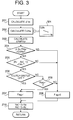
- Referring to Figure 3, the shift shock detection is executed according to the flowchart illustrated.
ECU 5 at thefirst step 201 subtracts the previous engine revolution speed Ne(-1) from the current engine revolution speed Ne to calculate the engine revolution speed change rate ΔNe (Ne - Ne(-1)). At thenext step 202, ECU obtains the threshold value CΔNe from a map M4 based on the current engine revolution speed Ne. The map M4 is prepared beforehand from experiments or theoretical computations, and stored inECU 5. As illustrated, the threshold value CΔNe varies with the engine speed Ne; the threshold value has a low value when the engine speed Ne is high. - At the
step 203, the filtered value ΔNeFilter is obtained according to the method as described earlier. This filtered value is then compared with the threshold value CΔNe at thenext step 204. If ΔNeFilter is smaller than or equal to CΔNe, the program proceeds to step 208 to establish that a shift shock flag is not raised (Flag = 0). - On the other hand, if ΔNeFilter > CΔNe, then the program proceeds to step 205 to compare the absolute value |Ac-Ac(-1)| obtained by subtracting the previous accelerator opening Ac(-1) from the current accelerator opening Ac with the predetermined accelerator opening change threshold value CAc. Here, it is determined if the change of the engine revolution speed Ne is caused by the accelerator pedal movement (stamped or released). If the engine revolution speed change is caused by the driver's foot stamping/releasing the accelerator pedal, the control of the present invention should not be performed. To this end, when |Ac-Ac(-1)| ≧ CAc is true, the program advances to step 208 to set the shift shock flag to be 0.
- If |Ac-Ac(-1)| < CAc, the program proceeds to step 206 to determine whether the
clutch switch 20 is off (i.e., the clutch is engaged). If the clutch switch is off,ECU 5 determines that there is shift shock. Accordingly, the program goes to step 207 to set the shift shock flag to be 1. On the other hand, if the clutch switch is on (i.e., the clutch is disengaged), the program proceeds to step 209 and determines whether Flag = 1 is already established. If the answer is No, then the program proceeds to step 207 and sets the flag to be 0. Subsequently, atstep 210, the current engine revolution speed Ne and accelerator opening Ac are changed to the previous values Ne(-1) and Ac(-1) for the next routine of control. In this manner, one routine of control ends. - When Flag = 1 is already established, the situation of Flag = 1 is maintained, even if the clutch is in the disengaged condition (
steps - Now, determination of target amount of fuel injection by the apparatus of the invention will be described. Figure 1 illustrates a block diagram of parts and maps related to this control and Figure 2 illustrates the flowchart of the same control. In other words, Figures 1 and 2 illustrate the substantially the same thing.
- Referring to Figure 1, three maps M1, M2 and M3 are stored in
ECU 5. These maps are prepared beforehand from experiments and/or theoretical computations. The map M1 is a three-dimensional map to determine a basic amount of fuel injection Qbase. The basic amount of fuel injection is uniquely determined from the engine revolution speed Ne detected by theengine speed sensor 16 and the accelerator opening degree Ac detected by theaccelerator sensor 17. This way of determining the basic amount of fuel injection using a map is common in the technical field of fuel injection control. Further, it is conventional to amend the basic amount of fuel injection Qbase with the engine water temperature and/or intake air temperature. For the sake of simplicity, in this particular specification, however, such amendment is not performed. - The map M2 is also a three-dimensional map to primarily determine an amount of first fuel injection Qbsh after the engine revolution speed change occurs (see the curve Qfnl in Figure 5). This amount of first injection Qbsh is uniquely determined from the engine speed Ne and the water temperature Tw detected by the water temperature sensor 21.
- The Map3 is a two-dimensional map to determine the subtraction value Qred, which is a value utilized in a subtracting calculation made to the amount of fuel injection in the revolution speed change suppression control. The value Qred is uniquely determined from the engine speed Ne.
- As depicted, when the shift shock flag is not raised (Flag = 0) (i.e., in the case of no shift shock), the basic amount of fuel injection Qbase is identical to the ultimate (target) amount of fuel injection Qfnl. Acomparator 22 chooses a larger one from the two inputs Qbase and Qshiftfnl. Since Flag = 0 and Qshiftfnl = 0, Qbase is output from the
comparator 22 and becomes Qfnl. - From this situation, it should be assumed that the shift shock occurs and the shift shock flag is raised (Flag = 1). First, a
switchover element 23 takes a value 0 (the reason will be described later) so that the amount of first fuel injection Qbsh becomes the output Qshift of theelement 23. Then, the output becomes Qshiftfnl and is input to thecomparator 22. Another input to thecomparator 22 is Qbase, which is smaller than Qbsh since currently the engine brake is applying and the accelerator opening degree Ac is almost zero. Accordingly, the first amount of fuel injection Qbsh, which is obtained by adding a certain value to the basic amount of fuel injection Qbase and therefore greater than it, becomes the ultimate (or target) amount of fuel injection Qfnl. - The condition for switching the
switch 23 to "1" is either the amount of previous target fuel injection Qfnl(-1) is identical to the amount of previous first fuel injection Qbsh(-1) or it is identical to the amount of previous minimum fuel injection Qmin (-1) (will be described later). Since Qbsh = Qfnl is established, theswitch 23 takes "1" for a while. - In the second routine of control after the shift shock determination, the amount of first fuel injection Qbsh is input to a
second comparator 24. Another input to thiscomparator 24 is an amount of reduced fuel injection Qdmp. This value Qdmp is obtained by subtracting the value Qred from the previous output Qshift(-1) of theswitch 23, i.e., the amount of previous first fuel injection Qbsh. Among these two inputs, thiscomparator 24 outputs the smaller one as the minimum amount of fuel injection Qmin. In most cases, Qdmp < Qbsh is established so that Qdmp becomes Qmin. This in turns results in Qshift and Qshiftfnl. Since the subtraction value Qred is a small value, the relationship of Qshiftfnl > Qbase is still established in thecomparator 22. Thus, Qshiftfnl (= Qdmp) becomes the target amount of fuel injection Qfnl. - In this manner, the target amount of fuel injection again takes a value greater than the basic amount of fuel injection Qbase. Since Qmin = Qfnl, the
switch 23 still takes "1" in the next routine of control. - In the subsequent control, as long as Flag = 1 is established, the target amount of fuel injection Qfnl is determined in the same manner as described above. As a result of subtracting the value Qred in each routine of control, the target amount of fuel injection Qfnl is gradually decreased from the starting value Qbsh as the time passes (see the curve Qfnl in Figure 5). However, the value Qfnl is still greater than the basic value Qbase.
- What is meant by this will be described below. When the engine brake is applying during the shift-down operation, the engine revolution speed changes dramatically upon clutch engagement because the inertia of the vehicle forces the engine to rapidly accelerate under the condition of the accelerator pedal being completely released and thus the fuel being injected in a small amount. As a result, great deceleration (engine brake) acts onto the vehicle, and immediately a reaction takes place. Due to this, the engine revolution speed varies in a large amplitude.
- According to the control of the present invention, the amount of fuel injection is slightly raised as the engine revolution speed change occurs. Therefore, the deceleration of the vehicle and its reaction are suppressed, and the engine revolution speed fluctuation and the back and forth movement of the vehicle is reduced. Consequently, the passengers in the vehicle do not experience uncomfortableness. Nevertheless, the amount of addition to the fuel injection is limited to the minimum since the engine brake is applying. The amount of first fuel injection Qbsh should be determined in view of this.
- The same fuel injection control as described above may be realized by the driver if he/she can stamp and release the accelerator pedal appropriately. In reality, however, such manual (or foot) control of the accelerator pedal requires a high skill and is complicated. Thus, it is not practical. The present invention, on the other hand, provides the apparatus and method of automatically performing such control.
- When the revolution speed change disappears and Flag = 0 is established, Qfnl = Qbase holds true. Then, the condition of switching the
switch 23 is no longer met. As a result, in the next control, it becomes "0" and the situation is returned to the initial condition. - The above control is diagramed in the flowchart of Figure 2. At
step 101,ECU 5 reads the basic amount of fuel injection Qbase from the map M1. Atstep 102,ECU 5 also reads the amount of initial fuel injection Qbsh from the second map M2. Atstep 103,ECU 5 further reads the subtraction value Qred from the third map M3. Atstep 104,ECU 5 calculates Qdmp according to the equation of Qdmp = Qshift(-1) - Qred. Atstep 105,ECU 5 takes the smaller one of the initial value Qbsh and the reduced value Qdmp as the minimum amount of fuel injection Qmin. - At
step 106,ECU 5 determines whether either Qfnl(-1) = Qbsh(-1) or Qfnl(-1) = Qmin(-1) holds true. If neither relation is established, the program proceeds to step 107 to make Qshift = Qbsh. If one of the relation is established, on the other hand, the program proceeds to step 108 to make Qshift = Qmin. - After that, at
step 109,ECU 5 determines whether the shift flag is raised (Flag = 1) or not. If Flag = 1, Qshift is made the final value Qshiftfnl atstep 110. If Flag = 0, the final value Qhiftfnl becomes 0 atstep 111. Atstep 112, the final value Qshiftfnl is compared with Qbase and the larger one is taken as the target amount of fuel injection Qfnl. Subsequently, atstep 113, the current values Qbsh, Qmin, Qshift and Qfnl are renamed to the previous values Qbsh(-1), Qmin(-1), Qshift(-1) and Qfnl(-1) for use in the next control. The program is then terminated. - It should be recalled that the revolution speed change threshold value CΔNe varies with the engine revolution speed Ne (map M4 in Figure 3). In particular, this threshold value is small when the engine revolution speed Ne is high, as indicated in the map M4. This is because the higher the engine revolution speed Ne, the larger the shift shock upon clutch engagement. The amount of first fuel injection Qbsh is adjusted in accordance with the water temperature Tw because the minimum amount of fuel injection required for engine acceleration varies with the water temperature Tw.
- It should be noted that the present invention is not limited to the above described embodiments. For instance, the present invention is applicable to a common rail type (accumulation type) fuel injection system.
Claims (10)
- An apparatus for controlling an amount of fuel to be injected into a diesel engine (1), comprising:a first sensor (5, 16) for determining whether change (ΔNe) in engine revolution speed (Ne) exceeds a predetermined value;a second sensor (5, 17) for determining whether an accelerator opening (Ac) stays within a predetermined range; anda controller (5) for determining a target amount of fuel injection (Qfnl) that is greater than a basic amount of fuel injection (Qbase) when the engine revolution speed change exceeds the predetermined amount and the accelerator opening stays in the predetermined range.
- The apparatus according to claim 1, characterized in that the first sensor determines whether the engine revolution speed change exceeds the predetermined value by comparing a filtered value (ΔNeFilter) of engine revolution speed change rate (ΔNe) with a threshold value (CΔNe) that changes with the engine revolution speed (Ne).
- The apparatus according to claim 1 or 2, characterized in that the controller determines the target amount of fuel injection based on the engine revolution speed (Ne) and temperature (Tw) of water flowing in the engine (1).
- The apparatus according to claim 1, 2 or 3, characterized in that the first sensor makes determination at prescribed intervals, and once the first sensor determines that the engine revolution speed change exceeds the predetermined value, a previous value of engine revolution speed change is also considered in a next determination.
- The apparatus according to claim 2, 3 or 4, characterized in that the threshold value takes a low value when the engine revolution speed is high.
- The apparatus according to any one of foregoing claims, characterized in that the controller determines a target amount of fuel injection greater the basic amount of fuel injection even after a clutch is disengaged.
- The apparatus according to any one of foregoing claims, characterized in that the basic amount (Qbase) of fuel injection is determined based on the engine revolution speed (Ne) and the accelerator opening (Ac).
- The apparatus according to claim 7, characterized in that the basic amount (Qbase) of fuel injection is determined further based on temperature (Tw) of water flowing in the engine and temperature of intake air.
- The apparatus according to any one of foregoing claims, characterized in that the controller makes determination at prescribed intervals, and the target amount (Qfnl) of fuel injection is reduced in a next determination every time the controller determines the target amount of fuel injection.
- A method of controlling an amount of fuel to be injected into a diesel engine (1), comprising the steps of:A) determining whether change (ΔNe) in engine revolution speed exceeds a predetermined value;B) determining whether an accelerator opening (Ac) is within a predetermined range; andC) determining a target amount of fuel injection (Qfnl) that is greater than a basic amount of fuel injection (Qbase) when the engine revolution speed change exceeds the predetermined amount and the accelerator opening stays in the predetermined range.
Applications Claiming Priority (2)
| Application Number | Priority Date | Filing Date | Title |
|---|---|---|---|
| JP15250099 | 1999-05-31 | ||
| JP11152500A JP2000345886A (en) | 1999-05-31 | 1999-05-31 | Fuel injection control device for diesel engine |
Publications (3)
| Publication Number | Publication Date |
|---|---|
| EP1057994A2 true EP1057994A2 (en) | 2000-12-06 |
| EP1057994A3 EP1057994A3 (en) | 2002-06-26 |
| EP1057994B1 EP1057994B1 (en) | 2007-02-14 |
Family
ID=15541833
Family Applications (1)
| Application Number | Title | Priority Date | Filing Date |
|---|---|---|---|
| EP00111710A Expired - Lifetime EP1057994B1 (en) | 1999-05-31 | 2000-05-31 | Method and apparatus for controlling fuel injection in diesel engine |
Country Status (4)
| Country | Link |
|---|---|
| US (1) | US6321722B1 (en) |
| EP (1) | EP1057994B1 (en) |
| JP (1) | JP2000345886A (en) |
| DE (1) | DE60033336T2 (en) |
Families Citing this family (7)
| Publication number | Priority date | Publication date | Assignee | Title |
|---|---|---|---|---|
| JP3607979B2 (en) * | 1999-11-19 | 2005-01-05 | トヨタ自動車株式会社 | Vehicle deceleration force control device |
| DE10139880C1 (en) * | 2001-08-20 | 2003-04-30 | Dolmar Gmbh | Method for regulating fuel supply to a two-stroke internal combustion engine for chainsaw uses on/off-switching of fuel supply to control an engine's parameters at a preset setting value after being retarded |
| ATE520957T1 (en) | 2005-01-18 | 2011-09-15 | Teleflex Inc | PEDAL ARRANGEMENT |
| JP4642616B2 (en) * | 2005-09-15 | 2011-03-02 | 川崎重工業株式会社 | Engine fuel supply method, fuel supply amount control device, and motorcycle including the control device |
| JP5370066B2 (en) * | 2009-10-15 | 2013-12-18 | トヨタ自動車株式会社 | Control device for internal combustion engine |
| CN105463776B (en) * | 2014-08-29 | 2019-04-05 | 青岛海尔洗衣机有限公司 | A kind of washing machine sunpender falls off detection device and washing machine method for safe operation |
| SE543784C2 (en) * | 2019-11-29 | 2021-07-20 | Scania Cv Ab | System and method for operating a fuel supply pump of a vehicle |
Family Cites Families (6)
| Publication number | Priority date | Publication date | Assignee | Title |
|---|---|---|---|---|
| EP0073475B1 (en) * | 1981-08-27 | 1988-02-03 | Nissan Motor Co., Ltd. | Control apparatus and method for engine-continuously variable transmission |
| US4502437A (en) * | 1981-11-02 | 1985-03-05 | Ambac Industries, Incorporated | Electrical fuel control system and method for diesel engines |
| JPS6217328A (en) * | 1985-07-15 | 1987-01-26 | Diesel Kiki Co Ltd | Control device for internal-combustion vehicle |
| JPH05296093A (en) * | 1992-04-15 | 1993-11-09 | Zexel Corp | Electronic governor of fuel injection device for internal combustion engine |
| JP2762350B2 (en) * | 1995-06-23 | 1998-06-04 | 株式会社ゼクセル | Idle rotation control apparatus and method for diesel engine |
| JP3514077B2 (en) * | 1997-06-24 | 2004-03-31 | 日産自動車株式会社 | Engine throttle control |
-
1999
- 1999-05-31 JP JP11152500A patent/JP2000345886A/en active Pending
-
2000
- 2000-05-26 US US09/579,685 patent/US6321722B1/en not_active Expired - Fee Related
- 2000-05-31 EP EP00111710A patent/EP1057994B1/en not_active Expired - Lifetime
- 2000-05-31 DE DE60033336T patent/DE60033336T2/en not_active Expired - Lifetime
Non-Patent Citations (1)
| Title |
|---|
| None |
Also Published As
| Publication number | Publication date |
|---|---|
| EP1057994A3 (en) | 2002-06-26 |
| EP1057994B1 (en) | 2007-02-14 |
| DE60033336T2 (en) | 2007-06-21 |
| DE60033336D1 (en) | 2007-03-29 |
| US6321722B1 (en) | 2001-11-27 |
| JP2000345886A (en) | 2000-12-12 |
Similar Documents
| Publication | Publication Date | Title |
|---|---|---|
| US6192857B1 (en) | Control apparatus of engine with electronically driven intake and exhaust valves | |
| JP3815096B2 (en) | Brake operation detection method for idle stop system | |
| US6047681A (en) | Process and apparatus for adjusting the torque of an interal-combustion engine | |
| EP1363006B1 (en) | Method of calculating engine torque | |
| EP1577524A2 (en) | Regeneration of diesel particulate filter | |
| JPS6347891B2 (en) | ||
| KR20100133949A (en) | Method and apparatus for controlling the output torque of an automatic transmission coupled to an internal combustion engine | |
| US20120010796A1 (en) | Control system and method for shift quality and performance improvement in manual transmissions using engine speed control | |
| US9522597B2 (en) | Methods and system for providing vehicle performance feedback | |
| JP4039257B2 (en) | Fuel injection amount control device | |
| RU2693369C2 (en) | Method to reduce pressure in engine intake manifold (versions) | |
| US6321722B1 (en) | Method and apparatus for controlling fuel injection in diesel engine | |
| EP1057993B1 (en) | Method and apparatus for controlling fuel injection in diesel engine | |
| JP2000073824A (en) | Electronic control unit for generating a fuel supply signal for an internal combustion engine | |
| US4788954A (en) | Method for controlling by-pass air flow on deceleration of internal combustion engine | |
| KR20130017956A (en) | Control method for idle throttle valve of diesel vehicle | |
| JPS61129340A (en) | Speed change control method of automatic transmission for vehicle | |
| JPH07166931A (en) | Engine fuel injection control device | |
| EP0924417A2 (en) | Transient injection quantity control apparatus and method of diesel engine | |
| WO2007122470A2 (en) | Control apparatus and method for vehicle | |
| JP3692763B2 (en) | Electronically controlled fuel injection system for diesel engines | |
| JPH1150875A (en) | Vehicle brake system | |
| JP4051779B2 (en) | Vehicle speed control device | |
| EP2613043B1 (en) | Control device for vehicle | |
| JPH0325622B2 (en) |
Legal Events
| Date | Code | Title | Description |
|---|---|---|---|
| PUAI | Public reference made under article 153(3) epc to a published international application that has entered the european phase |
Free format text: ORIGINAL CODE: 0009012 |
|
| AK | Designated contracting states |
Kind code of ref document: A2 Designated state(s): AT BE CH CY DE DK ES FI FR GB GR IE IT LI LU MC NL PT SE |
|
| AX | Request for extension of the european patent |
Free format text: AL;LT;LV;MK;RO;SI |
|
| PUAL | Search report despatched |
Free format text: ORIGINAL CODE: 0009013 |
|
| AK | Designated contracting states |
Kind code of ref document: A3 Designated state(s): AT BE CH CY DE DK ES FI FR GB GR IE IT LI LU MC NL PT SE |
|
| AX | Request for extension of the european patent |
Free format text: AL;LT;LV;MK;RO;SI |
|
| RIC1 | Information provided on ipc code assigned before grant |
Free format text: 7F 02D 41/38 A, 7F 02D 41/40 B, 7F 02D 41/14 B |
|
| 17P | Request for examination filed |
Effective date: 20020930 |
|
| AKX | Designation fees paid |
Designated state(s): AT BE CH LI |
|
| RBV | Designated contracting states (corrected) |
Designated state(s): DE FR GB |
|
| REG | Reference to a national code |
Ref country code: DE Ref legal event code: 8566 |
|
| 17Q | First examination report despatched |
Effective date: 20050331 |
|
| GRAP | Despatch of communication of intention to grant a patent |
Free format text: ORIGINAL CODE: EPIDOSNIGR1 |
|
| GRAS | Grant fee paid |
Free format text: ORIGINAL CODE: EPIDOSNIGR3 |
|
| GRAA | (expected) grant |
Free format text: ORIGINAL CODE: 0009210 |
|
| AK | Designated contracting states |
Kind code of ref document: B1 Designated state(s): DE FR GB |
|
| REG | Reference to a national code |
Ref country code: GB Ref legal event code: FG4D |
|
| REF | Corresponds to: |
Ref document number: 60033336 Country of ref document: DE Date of ref document: 20070329 Kind code of ref document: P |
|
| EN | Fr: translation not filed | ||
| PLBE | No opposition filed within time limit |
Free format text: ORIGINAL CODE: 0009261 |
|
| STAA | Information on the status of an ep patent application or granted ep patent |
Free format text: STATUS: NO OPPOSITION FILED WITHIN TIME LIMIT |
|
| 26N | No opposition filed |
Effective date: 20071115 |
|
| GBPC | Gb: european patent ceased through non-payment of renewal fee |
Effective date: 20070531 |
|
| PG25 | Lapsed in a contracting state [announced via postgrant information from national office to epo] |
Ref country code: FR Free format text: LAPSE BECAUSE OF FAILURE TO SUBMIT A TRANSLATION OF THE DESCRIPTION OR TO PAY THE FEE WITHIN THE PRESCRIBED TIME-LIMIT Effective date: 20071005 |
|
| PG25 | Lapsed in a contracting state [announced via postgrant information from national office to epo] |
Ref country code: GB Free format text: LAPSE BECAUSE OF NON-PAYMENT OF DUE FEES Effective date: 20070531 |
|
| PG25 | Lapsed in a contracting state [announced via postgrant information from national office to epo] |
Ref country code: FR Free format text: LAPSE BECAUSE OF FAILURE TO SUBMIT A TRANSLATION OF THE DESCRIPTION OR TO PAY THE FEE WITHIN THE PRESCRIBED TIME-LIMIT Effective date: 20070214 |
|
| PGFP | Annual fee paid to national office [announced via postgrant information from national office to epo] |
Ref country code: DE Payment date: 20100526 Year of fee payment: 11 |
|
| REG | Reference to a national code |
Ref country code: DE Ref legal event code: R119 Ref document number: 60033336 Country of ref document: DE |
|
| REG | Reference to a national code |
Ref country code: DE Ref legal event code: R119 Ref document number: 60033336 Country of ref document: DE |
|
| PG25 | Lapsed in a contracting state [announced via postgrant information from national office to epo] |
Ref country code: DE Free format text: LAPSE BECAUSE OF NON-PAYMENT OF DUE FEES Effective date: 20111130 |