EP1057984A2 - Exhaust pipe layout structure for vehicles - Google Patents
Exhaust pipe layout structure for vehicles Download PDFInfo
- Publication number
- EP1057984A2 EP1057984A2 EP00111282A EP00111282A EP1057984A2 EP 1057984 A2 EP1057984 A2 EP 1057984A2 EP 00111282 A EP00111282 A EP 00111282A EP 00111282 A EP00111282 A EP 00111282A EP 1057984 A2 EP1057984 A2 EP 1057984A2
- Authority
- EP
- European Patent Office
- Prior art keywords
- exhaust pipe
- inclined portion
- disposed
- engine
- flexible joint
- Prior art date
- Legal status (The legal status is an assumption and is not a legal conclusion. Google has not performed a legal analysis and makes no representation as to the accuracy of the status listed.)
- Granted
Links
Images



Classifications
-
- F—MECHANICAL ENGINEERING; LIGHTING; HEATING; WEAPONS; BLASTING
- F01—MACHINES OR ENGINES IN GENERAL; ENGINE PLANTS IN GENERAL; STEAM ENGINES
- F01N—GAS-FLOW SILENCERS OR EXHAUST APPARATUS FOR MACHINES OR ENGINES IN GENERAL; GAS-FLOW SILENCERS OR EXHAUST APPARATUS FOR INTERNAL-COMBUSTION ENGINES
- F01N13/00—Exhaust or silencing apparatus characterised by constructional features
- F01N13/18—Construction facilitating manufacture, assembly, or disassembly
- F01N13/1805—Fixing exhaust manifolds, exhaust pipes or pipe sections to each other, to engine or to vehicle body
- F01N13/1811—Fixing exhaust manifolds, exhaust pipes or pipe sections to each other, to engine or to vehicle body with means permitting relative movement, e.g. compensation of thermal expansion or vibration
- F01N13/1822—Fixing exhaust manifolds, exhaust pipes or pipe sections to each other, to engine or to vehicle body with means permitting relative movement, e.g. compensation of thermal expansion or vibration for fixing exhaust pipes or devices to vehicle body
-
- F—MECHANICAL ENGINEERING; LIGHTING; HEATING; WEAPONS; BLASTING
- F01—MACHINES OR ENGINES IN GENERAL; ENGINE PLANTS IN GENERAL; STEAM ENGINES
- F01N—GAS-FLOW SILENCERS OR EXHAUST APPARATUS FOR MACHINES OR ENGINES IN GENERAL; GAS-FLOW SILENCERS OR EXHAUST APPARATUS FOR INTERNAL-COMBUSTION ENGINES
- F01N13/00—Exhaust or silencing apparatus characterised by constructional features
- F01N13/08—Other arrangements or adaptations of exhaust conduits
-
- F—MECHANICAL ENGINEERING; LIGHTING; HEATING; WEAPONS; BLASTING
- F01—MACHINES OR ENGINES IN GENERAL; ENGINE PLANTS IN GENERAL; STEAM ENGINES
- F01N—GAS-FLOW SILENCERS OR EXHAUST APPARATUS FOR MACHINES OR ENGINES IN GENERAL; GAS-FLOW SILENCERS OR EXHAUST APPARATUS FOR INTERNAL-COMBUSTION ENGINES
- F01N13/00—Exhaust or silencing apparatus characterised by constructional features
- F01N13/18—Construction facilitating manufacture, assembly, or disassembly
- F01N13/1805—Fixing exhaust manifolds, exhaust pipes or pipe sections to each other, to engine or to vehicle body
- F01N13/1811—Fixing exhaust manifolds, exhaust pipes or pipe sections to each other, to engine or to vehicle body with means permitting relative movement, e.g. compensation of thermal expansion or vibration
-
- F—MECHANICAL ENGINEERING; LIGHTING; HEATING; WEAPONS; BLASTING
- F01—MACHINES OR ENGINES IN GENERAL; ENGINE PLANTS IN GENERAL; STEAM ENGINES
- F01N—GAS-FLOW SILENCERS OR EXHAUST APPARATUS FOR MACHINES OR ENGINES IN GENERAL; GAS-FLOW SILENCERS OR EXHAUST APPARATUS FOR INTERNAL-COMBUSTION ENGINES
- F01N3/00—Exhaust or silencing apparatus having means for purifying, rendering innocuous, or otherwise treating exhaust
- F01N3/08—Exhaust or silencing apparatus having means for purifying, rendering innocuous, or otherwise treating exhaust for rendering innocuous
- F01N3/10—Exhaust or silencing apparatus having means for purifying, rendering innocuous, or otherwise treating exhaust for rendering innocuous by thermal or catalytic conversion of noxious components of exhaust
- F01N3/24—Exhaust or silencing apparatus having means for purifying, rendering innocuous, or otherwise treating exhaust for rendering innocuous by thermal or catalytic conversion of noxious components of exhaust characterised by constructional aspects of converting apparatus
- F01N3/28—Construction of catalytic reactors
-
- F—MECHANICAL ENGINEERING; LIGHTING; HEATING; WEAPONS; BLASTING
- F01—MACHINES OR ENGINES IN GENERAL; ENGINE PLANTS IN GENERAL; STEAM ENGINES
- F01N—GAS-FLOW SILENCERS OR EXHAUST APPARATUS FOR MACHINES OR ENGINES IN GENERAL; GAS-FLOW SILENCERS OR EXHAUST APPARATUS FOR INTERNAL-COMBUSTION ENGINES
- F01N2340/00—Dimensional characteristics of the exhaust system, e.g. length, diameter or volume of the exhaust apparatus; Spatial arrangements of exhaust apparatuses
- F01N2340/04—Arrangement of the exhaust system relative to a vehicle or parts thereof
-
- Y—GENERAL TAGGING OF NEW TECHNOLOGICAL DEVELOPMENTS; GENERAL TAGGING OF CROSS-SECTIONAL TECHNOLOGIES SPANNING OVER SEVERAL SECTIONS OF THE IPC; TECHNICAL SUBJECTS COVERED BY FORMER USPC CROSS-REFERENCE ART COLLECTIONS [XRACs] AND DIGESTS
- Y02—TECHNOLOGIES OR APPLICATIONS FOR MITIGATION OR ADAPTATION AGAINST CLIMATE CHANGE
- Y02A—TECHNOLOGIES FOR ADAPTATION TO CLIMATE CHANGE
- Y02A50/00—TECHNOLOGIES FOR ADAPTATION TO CLIMATE CHANGE in human health protection, e.g. against extreme weather
- Y02A50/20—Air quality improvement or preservation, e.g. vehicle emission control or emission reduction by using catalytic converters
Definitions
- the present invention relates to an exhaust pipe layout structure for vehicles in which an engine having a cylinder head disposed on an upper side thereof and a transmission coupled to the engine are transversely mounted at a front portion of a vehicle body and in which an exhaust pipe extends from an exhaust manifold coupled to a rear side of the cylinder head extends toward the rear of the vehicle body.
- An exhaust pipe layout structure as described above is known in Japanese Patent Unexamined Publication No. Hei. 5-1530(JP-A-5-1530).
- a power unit is transversely mounted which comprises an engine and a transmission which are made integral with the engine being disposed such that the crankshaft is oriented in a transverse direction of the vehicle body and that the axes of the cylinders are inclined rearward.
- an exhaust pipe having an inclined portion extending toward the rear in a downward direction and a horizontal portion extending to the rear is connected to a rear end of an exhaust manifold coupled to a rear side of a cylinder head of the engine, and a catalyzer is connected to a rear end of the exhaust pipe.
- the exhaust pipe is connected to the exhaust manifold and the catalyzer via flexible joints at the front and rear ends thereof, respectively.
- the vibration of the exhaust pipe is designed to be controlled by disposing the roll center of the power unit and the two flexible joints in a specific positional relationship.
- the drive shafts for driving the left and right front wheels extend in transverse directions of the vehicle body from a rear portion of the transmission, and the steering gear box for steering the front wheels is disposed behind the drive shafts in such a manner as to be oriented in a transverse direction of the vehicle body.
- the exhaust pipe extending from the exhaust manifold coupled to the rear side of the cylinder head is tried to be led downwardly below the floor panel, since the exhaust pipe comes to interfere with the drive shafts and the steering gear box, it is difficult to provide a compact layout.
- the present invention has been made in view of the above circumstances, and objects thereof are to provide a compact layout for an exhaust pipe of vehicles in which an exhaust pipe extends from a rear side of a transversely mounted power unit toward the rear of a vehicle body of the vehicle, wherein the exhaust pipe is laid out in such a manner as not to interfere with drive shafts for front wheels and a steering gear box and to provide a layout for an exhaust pipe wherein an exhaust pipe is laid out in such a manner as not to interrupt the impact absorption effect when the vehicle crashes.
- an exhaust pipe layout structure for vehicles in which an engine having a cylinder head disposed on an upper side thereof and a transmission coupled to the engine are transversely mounted at a front portion of a vehicle body and in which the exhaust pipe extends from an exhaust manifold coupled to a rear side of the cylinder head extends toward the rear of the vehicle body, characterized in that the exhaust pipe has an inclined portion extending from the exhaust manifold toward the rear in a downward direction, in that a drive shaft for a front wheel extending transversely from the transmission is disposed in front of the inclined portion and in that a steering gear box is disposed behind the inclined portion.
- the drive shaft, exhaust pipe and steering gear box can be rationally disposed behind the engine to save and reduce a space required therefor, while maintaining an appropriate position of the steering gear box relative to the front wheels.
- an exhaust pipe layout structure for vehicles wherein a pre-catalyzer disposed at a connecting portion between the exhaust manifold and the exhaust pipe and the steering gear box are offset vertically.
- an exhaust pipe layout structure for vehicles in which an engine having a cylinder head disposed on an upper side thereof and a transmission coupled to the engine are transversely mounted at a front portion of a vehicle body and in which the exhaust pipe extends from an exhaust manifold coupled to a rear side of the cylinder head toward the rear of the vehicle body, characterized in that the exhaust pipe has a first inclined portion extending from the exhaust manifold toward the rear in a downward direction and a second inclined portion extending from a lowest point at a rear end of the first inclined portion toward the rear in an upward direction, and in that a pair of flexible joints adapted to permit the deflection of the exhaust pipe are disposed, respectively, at the first inclined portion and the second inclined portion which are disposed in front of and behind the lowest point, respectively.
- the exhaust pipe comprises the first inclined portion extending from the exhaust manifold toward the rear in the downward direction and the second inclined portion extending from the lowest point at the rear end of the first inclined portion toward the rear in the upward direction, and since there are provided the flexible joints at the first inclined portion and the second inclined portion, respectively, not only can the deflection of the exhaust pipe entailed by the rolling of the engine be absorbed but also the impact absorption effect can be improved by allowing the exhaust pipe to be bent into a V-shape at the lowest point by virtue of a load applied from the front of the vehicle when it crashes.
- a first exhaust pipe 23 and a second exhaust pipe 25 in an embodiment correspond to the exhaust pipe of the invention
- a fist flexible joint 24 and a second flexible joint 26 of the embodiment correspond to the flexible joints of the invention
- a floor panel 38 of the embodiment corresponds to the vehicle body of the invention
- a first inclined portion S1 corresponds to the inclined portion of the invention.
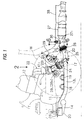
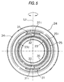
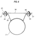
- Figs. 1 to 7 show one embodiment of the invention, in which Fig. 1 is a side view of a front portion of a vehicle body of a front-wheel-drive vehicle, Fig. 2 is a view seen in a direction indicated by an arrow 2 of Fig. 1, Fig. 3 is an enlarged view showing a main portion of Fig. 1, Fig. 4 is an enlarged sectional view taken along the line 4-4 of Fig. 1, Fig. 5 is an enlarged sectional view taken along the line 5-5 of Fig. 4, Fig. 6 is an enlarged sectional view taken along the line 6-6 of Fig. 6, and Fig. 7 is a view explaining an operation of the invention.
- a power unit P comprising an in-line four-cylinder engine E disposed on the front right-hand side of a vehicle body and a transmission T disposed on the front left-hand side thereof which are made integral are transversely mounted on a front sub-frame 11 formed into a quadrilateral frame-like shape with the axis L1 of a crankshaft being oriented in a transverse direction of the vehicle body and a cylinder head 12 being disposed on the upper side of the engine.
- the front sub-frame 11 comprises left and right side members 13L, 13R, a front member 14 and a rear member 15.
- a front portion of the engine E is supported on the front member 14 via front mounts 16, and a rear portion of the engine E is supported on the rear member 15 via rear mounts 17.
- a left end portion of the transmission T is supported on the left side member 13L via a pair of side mounts 18, 19.
- the sub-frame 11 on which the power unit P is mounted is supported on lower surfaces of left and right main frames 21L, 21R extending in a longitudinal direction of the vehicle body via sub-frame mounts 20 . . . provided at four corners of the sub-frame 11.
- an exhaust manifold 22 curved downwardly is coupled to a rear side of the cylinder head 12 of the engine E, and a coupling flange 23 of a first exhaust pipe 23 is coupled to a coupling flange 41 1 off a pre-catalyzer 41 provided at a downstream end of the exhaust manifold 22, an upstream end of a second exhaust pipe 25 is coupled to a downstream end of this first exhaust pipe 23 via a first flexible joint 24, and an exhaust gas introduction pipe 27 1 of a catalyzer 27 is coupled to a downstream end of this second exhaust pipe 25 via a second flexible joint 26.
- the first exhaust pipe 23 is formed linearly and is disposed so as to incline toward the rear in a downward direction from a front upper end thereof.
- the second exhaust pipe 25 is curved into an arc-like shape having a central angle of about 120 degrees, and upstream and downstream ends of the second exhaust pipe 25 both incline upwardly.
- the second exhaust pipe 25 is disposed downwardly convexly such that a central portion thereof becomes a lowest point B.
- a first inclined portion S1 is a portion ranging from the upstream end of the first exhaust pipe 23 to the lowest point B of the second exhaust pipe 25, in other words, the fist exhaust pipe 23 and a portion of the second exhaust pipe 25 which inclines toward the rear in the downward direction, while a portion ranging from the lowest point B to the downstream end of the second exhaust pipe 25 or a portion of the second exhaust pipe 25 which inclines toward the rear in an upward direction is defined as a second inclined portion S2.
- Left and right drive shafts 28L, 28R extend from the transmission T in transverse directions of the vehicle body, and distal ends of these drive shafts 28L, 28R are connected to left and right front wheels, respectively.
- the drive shaft 28R extending rightward from the transmission T is disposed directly in front of the first exhaust pipe 23 and a steering gear box 29 for steering the left and right front wheels W, W is disposed directly behind the first exhaust pipe 23 at a height as substantially high as the right drive shaft 28R.
- the right drive shaft 28R is situated more forward than the first flexible joint 24, and the steering gear box 29 is situated more rearward than the first flexible joint 24 but more forward than the second flexible joint 26.
- the pre-catalyzer 41 is disposed so as to be offset to a higher position relative to the steering gear box 29 which is situated behind the pre-catalyzer 41.
- the construction of the second flexible joint 26 is substantially identical to that of the first flexible joint 24, and therefore the description thereof will be omitted in order to avoid a repeated description.
- the first flexible joint 24 for providing a flexible joint between the first exhaust pipe 23 and the second exhaust pipe 25 by fitting an inner peripheral surface of the upstream end of the second exhaust pipe 25 over an outer peripheral surface of the downstream end of the first exhaust pipe 23 comprises an annular groove 23 2 formed in the outer peripheral surface of the first exhaust pipe 23, a pair of ball holders 31, 31 welded to diametrical ends of an enlarged diameter portion 251 of the second exhaust pipe 25, a pair of balls 32, 32 adapted to fit in depressed portions 31 1 , 31 1 formed in the pair of ball holders 31, 31 and the annular groove 23 2 , a flexible bellows pipe 34 welded to the outer peripheral surface of the first exhaust pipe 23 at one end thereof and to an outer peripheral surface of the second exhaust pipe 25 via a spacer 33 at the other end thereof, and a rectifier tube 35 welded to an inner peripheral surface of the first exhaust pipe 23 so as to cover a joint portion between both the exhaust pipes 23, 25.
- the first flexible joint 24 has an axis L2 (refer to Fig. 5) passing through the centers of the pair of balls 32, 32, and the oscillation of the first exhaust pipe 23 and the second exhaust pipe 25 is permitted around the axis L2 with these balls 32, 32 acting as a fulcrum.
- the axes L2 of the first flexible joint 24 and the second flexible joint 26 are disposed in a direction perpendicular to the surface of the paper illustrating Fig. 3 thereof. Therefore, the first exhaust pipe 23 and the second exhaust pipe 25 jointed to each other by the first flexible joint 24 can be oscillated relatively within a plane along the surface of the paper of Fig. 3.
- the roll center C of the power unit P, the axis L2 of the first flexible joint 24 and the axis L2 of the second flexible joint 26 are located on the same straight line L3 when viewed from the side.
- the roll center C is an axis acting as the center of rolling when the power unit P rolls by virtue of the inertia force resulting from the acceleration or deceleration of the engine E.
- a mounting bracket 36 is welded to the exhaust gas introduction pipe 27 1 of the catalyzer 27, and rubber bushes 37, 37 are fitted on ends of this mounting bracket 36. Stepped bolts 39, 39 penetrating through the rubber bushes 37, 37 and a floor panel 38 are tightened by nuts 40, 40, whereby the exhaust gas introduction pipe 27 1 of the catalyzer 27 is fixed in such a manner as to extend along a lower surface of the floor panel 38.
- the second flexible joint 26 is slightly moved forward by virtue of the elastic deformation of the rubber bushes 37, 37, and the second exhaust pipe 25 follows the movement of the first exhaust pipe 23.
- the forward movement of the second flexible joint 26 is suppressed to a minimum level when the first flexible joint 24 moves on the arc A1.
- bending stresses generated on the exhaust manifold 22, the first exhaust pipe 23 and the second exhaust pipe 25 when the power unit P rolls are suppressed to a minimum level, and deflected loads applied to the first flexible joint 24 and the second flexible joint 26 can be suppressed to a minimum level.
- the interruption of the rolling of the power unit P by the exhaust system is prevented, thereby making it possible to improve the vibration absorption properties.
- the first inclined portion S1 which inclines toward the rear in the downward direction is held between the first exhaust pipe 23 and the second exhaust pipe 25, and the right drive shaft 28R is disposed in front of the first inclined portion S1, while the steering gear box 29 is disposed behind the same, whereby the right drive shaft 28R, the first exhaust pipe 23, the second exhaust pipe 25 and the steering gear box 29 can be laid out compactly in a narrow space behind the power unit P.
- the steering gear box 29 is connected to the front wheels W, W via tie rods, and therefore its position cannot be moved forward limitlessly.
- a large longitudinal space is required behind the power unit P.
- the exhaust gas introduction pipe 27 1 of the catalyzer 27 is fixed to the floor panel 38, a compression load is applied to the exhaust manifold 22, the first exhaust pipe 23 and the second exhaust pipe 25. Since the first exhaust pipe 23 and the second exhaust pipe 25 have the first inclined portion S1 in front of the lowest point B and the second inclined portion S2 behind the lowest point B and are curved downwardly convexly as a whole, the first exhaust pipe 23 and the second exhaust pipe 25 are easily bent into a V-shape at the lowest point B by virtue of the compression load, whereby the impact absorption effect can be improved. In this case, the first exhaust pipe 23 and the second exhaust pipe 25 are relatively bent at the first flexible joint 24, and the second exhaust pipe 25 and the catalyzer 27 are relatively bent at the second flexible joint 26, whereby the impact absorption effect can further be improved.
- first flexible joint 24 and the second flexible joint 26 are disposed at positions higher than the lowest point B of the second exhaust pipe 25, there is eliminated a risk that the first flexible joint 24 and the second flexible joint 26 are brought into direct contact with a surface of a irregular road even when the vehicle is driven on such the irregular road, whereby the first flexible joint 24 and the second flexible joint 26 are prevented from being damaged.
- the drive shaft, exhaust pipe and steering gear box can be rationally disposed behind the engine to save and reduce a space required therefor, while maintaining an appropriate position of the steering gear box relative to the front wheels.
- the exhaust pipe comprises the first inclined portion extending from the exhaust manifold toward the rear in the downward direction and the second inclined portion extending from the lowest point at the rear end of the first inclined portion toward the rear in the upward direction, and since there are provided the flexible joints at the first inclined portion and the second inclined portion, respectively, not only can the deflection of the exhaust pipe entailed by the rolling of the engine be absorbed but also the impact absorption effect can be improved by allowing the exhaust pipe to be bent into a V-shape at the lowest point by virtue of a load applied from the front of the vehicle when it crashes.
- An exhaust pipe layout structure for vehicles comprises a first exhaust pipe extending from an exhaust manifold coupled to a rear side of a cylinder head of an engine toward the rear of a vehicle body, a second exhaust pipe and a catalyzer which are connected to each other with two flexible joints.
- a first inclined portion inclines toward the rear in a downward direction and a second inclined portion inclines toward the rear in an upward direction are provided in front of and behind a lowest point of the first and second exhaust pipes, respectively, and a drive shaft for a front wheel and a steering gear box for the front wheels are disposed in front of and behind the first inclined portion, respectively.
Landscapes
- Engineering & Computer Science (AREA)
- Chemical & Material Sciences (AREA)
- Combustion & Propulsion (AREA)
- Mechanical Engineering (AREA)
- General Engineering & Computer Science (AREA)
- Chemical Kinetics & Catalysis (AREA)
- Health & Medical Sciences (AREA)
- Toxicology (AREA)
- Cooling, Air Intake And Gas Exhaust, And Fuel Tank Arrangements In Propulsion Units (AREA)
- Exhaust Silencers (AREA)
Abstract
Description
Claims (11)
- An exhaust pipe layout structure for a vehicle, comprising:an engine;a cylinder head disposed on said engine;a transmission coupled to said engine, said engine and said transmission being transversely mounted at a front portion of a vehicle body;a manifold coupled to a rear side of said cylinder head;a drive shaft for a front wheel extending transversely from said transmission;a steering gear box for steering the front wheels; andan exhaust pipe comprising an inclined portion extending from said exhaust manifold toward the rear in a downward direction, said drive shaft is disposed in front of said inclined portion and said steering gear box is disposed behind said inclined portion.
- The exhaust pipe layout structure for vehicle according to claim 1, comprising a pre-catalyzer disposed at a connecting portion between said exhaust manifold and said exhaust pipe,
wherein said pre-catalyzer and said steering gear box are offset vertically. - An exhaust pipe layout structure for a vehicle, comprising:an engine;a cylinder head disposed on said engine;a transmission coupled to said engine, said engine and said transmission being transversely mounted at a front portion of a vehicle body;an exhaust manifold coupled to a rear side of said cylinder head;an exhaust pipe including a first inclined portion extending from said exhaust manifold toward the rear in a downward direction and a second inclined portion extending from a lowest point at a rear end of said first inclined portion toward the rear in an upward direction; anda pair of flexible joints being a first flexible joint disposed in said first inclined portion and a second flexible joint disposed in said second inclined portion.
- The exhaust pipe layout structure according to claim 3, wherein a roll center of a power unit, said first flexible joint and said second flexible joint are situated on the same straight line in a neutral state.
- The exhaust pipe layout structure according to claim 3, wherein said exhaust pipe is curved like an arc-like shape having a central angle of approximately 120 degrees.
- The exhaust pipe layout structure according to claim 3, wherein said first flexible joint and said second flexible joint are respectively disposed at positions higher than said lowest point of said exhaust pipe.
- The exhaust pipe layout structure according to claim 3, comprising:a drive shaft disposed in front of said first inclined portion; and,a steering gear box disposed behind said first inclined portion.
- A vehicle comprising:an exhaust pipe,
wherein said exhaust pipe comprising:a first inclined portion defined on between one end of said exhaust pipe and a lowest point;a second inclined portion defined on between said lowest point and the other end of said exhaust pipe;a first flexible joint disposed in said first inclined portion; anda second flexible joint disposed in said second inclined portion,
wherein said lowest point defined in between both end of said exhaust pipe, a position of said lowest point being lower than both end, wherein said exhaust pipe is approximately U-shape as a whole. - The vehicle according to claim 8, comprising:a cylinder head disposed on said engine;a transmission coupled to said engine, said engine and said transmission being transversely mounted at a front portion of said vehicle;a manifold coupled to a rear side of said cylinder head;a drive shaft extending transversely from said transmission; anda steering gear box for steering the front wheels,
wherein said first inclined portion is extending from said exhaust manifold toward the rear in a downward direction, said drive shaft is disposed in front of said first inclined portion and said steering gear box is disposed behind said first inclined portion. - The vehicle according to claim 9, comprising a pre-catalyzer connected one end of said exhaust pipe,
wherein said pre-catalyzer and said steering gear box are offset vertically. - The vehicle according to claim 8, wherein a roll center of a power unit, said first flexible joint and said second flexible joint are situated on the same straight line in a neutral state.
Applications Claiming Priority (2)
| Application Number | Priority Date | Filing Date | Title |
|---|---|---|---|
| JP15339399 | 1999-06-01 | ||
| JP11153393A JP2000345837A (en) | 1999-06-01 | 1999-06-01 | Arrangement structure of exhaust pipe in vehicle |
Publications (3)
| Publication Number | Publication Date |
|---|---|
| EP1057984A2 true EP1057984A2 (en) | 2000-12-06 |
| EP1057984A3 EP1057984A3 (en) | 2002-07-24 |
| EP1057984B1 EP1057984B1 (en) | 2003-12-17 |
Family
ID=15561521
Family Applications (1)
| Application Number | Title | Priority Date | Filing Date |
|---|---|---|---|
| EP00111282A Expired - Lifetime EP1057984B1 (en) | 1999-06-01 | 2000-05-25 | Exhaust pipe layout structure for vehicles |
Country Status (4)
| Country | Link |
|---|---|
| US (1) | US6378645B1 (en) |
| EP (1) | EP1057984B1 (en) |
| JP (1) | JP2000345837A (en) |
| DE (1) | DE60007222T2 (en) |
Cited By (4)
| Publication number | Priority date | Publication date | Assignee | Title |
|---|---|---|---|---|
| EP1116866A3 (en) * | 2000-01-13 | 2003-07-16 | Honda Giken Kogyo Kabushiki Kaisha | Exhaust pipe joint assembly |
| FR2883516A1 (en) * | 2005-03-22 | 2006-09-29 | Renault Sas | EXHAUST CATALYST STRAP HOLDING DEVICE |
| EP1707775A1 (en) * | 2005-03-09 | 2006-10-04 | Audi Ag | Motor vehicle exhaust system |
| EP1752634A1 (en) * | 2005-08-11 | 2007-02-14 | Nissan Motor Company Limited | Exhaust system |
Families Citing this family (23)
| Publication number | Priority date | Publication date | Assignee | Title |
|---|---|---|---|---|
| JP2001280127A (en) * | 2000-03-30 | 2001-10-10 | Honda Motor Co Ltd | Exhaust pipe system mounting structure for vehicles |
| JP3439432B2 (en) * | 2000-06-27 | 2003-08-25 | 本田技研工業株式会社 | Vehicle front structure |
| EP1188643B1 (en) * | 2000-09-19 | 2006-10-11 | Mazda Motor Corporation | Sub-frame structure of motor vehicle |
| US20040089492A1 (en) * | 2002-11-07 | 2004-05-13 | Arctic Cat, Inc. | Vehicle with inclined engine |
| DE10313568B4 (en) * | 2003-03-26 | 2005-04-28 | Zeuna Staerker Kg | motor vehicle |
| JP2005297734A (en) * | 2004-04-09 | 2005-10-27 | Toyota Motor Corp | Engine exhaust system |
| JP2006009753A (en) * | 2004-06-29 | 2006-01-12 | Nissan Motor Co Ltd | Engine exhaust system for vehicles |
| JP4496470B2 (en) * | 2004-07-29 | 2010-07-07 | スズキ株式会社 | Vehicle exhaust system |
| JP4276185B2 (en) * | 2005-01-26 | 2009-06-10 | 本田技研工業株式会社 | Body front structure |
| JP2008064068A (en) * | 2006-09-11 | 2008-03-21 | Yamaha Motor Co Ltd | Motorcycle |
| JP2008095527A (en) * | 2006-10-06 | 2008-04-24 | Toyota Motor Corp | Exhaust device for internal combustion engine |
| US7937936B2 (en) * | 2007-01-16 | 2011-05-10 | Deere & Company | Vehicle exhaust component arrangement |
| EP1980437B1 (en) * | 2007-04-13 | 2011-12-21 | Mazda Motor Corporation | Front structure of vehicle |
| US8596398B2 (en) | 2007-05-16 | 2013-12-03 | Polaris Industries Inc. | All terrain vehicle |
| US8302727B2 (en) * | 2007-09-12 | 2012-11-06 | Yamaha Hatsudoki Kabushiki Kaisha | Exhaust pipe for a vehicle |
| JP4905837B2 (en) * | 2007-10-03 | 2012-03-28 | スズキ株式会社 | Undercarriage of the vehicle |
| JP4919175B2 (en) * | 2008-06-10 | 2012-04-18 | スズキ株式会社 | Vehicle exhaust pipe structure |
| US8994494B2 (en) | 2008-10-10 | 2015-03-31 | Polaris Industries Inc. | Vehicle security system |
| US9096289B2 (en) | 2012-02-09 | 2015-08-04 | Polaris Industries Inc. | Snowmobile |
| US10358187B2 (en) | 2014-01-10 | 2019-07-23 | Polaris Industries Inc. | Snowmobile |
| US9845004B2 (en) * | 2014-01-10 | 2017-12-19 | Polaris Industries Inc. | Snowmobile |
| JP6894341B2 (en) * | 2017-10-10 | 2021-06-30 | トヨタ自動車株式会社 | Internal combustion engine exhaust system |
| US10793181B2 (en) | 2018-02-13 | 2020-10-06 | Polaris Industries Inc. | All-terrain vehicle |
Family Cites Families (13)
| Publication number | Priority date | Publication date | Assignee | Title |
|---|---|---|---|---|
| JPS58130020U (en) * | 1982-02-26 | 1983-09-02 | いすゞ自動車株式会社 | Flexible joint for automobile exhaust pipe |
| JPS6170118A (en) * | 1984-09-14 | 1986-04-10 | Yamaha Motor Co Ltd | Exhaust device of automobile engine |
| JPH02293271A (en) * | 1989-05-02 | 1990-12-04 | Mazda Motor Corp | Rear-wheel steering gear for vehicle |
| JPH02293269A (en) * | 1989-05-02 | 1990-12-04 | Mazda Motor Corp | Rear-wheel steering gear for vehicle |
| JP2502982Y2 (en) * | 1989-06-28 | 1996-06-26 | マツダ株式会社 | Engine exhaust system suspension system |
| US5195607A (en) * | 1989-11-21 | 1993-03-23 | Mazda Motor Corporation | Exhaust system for automotive engine |
| JPH04224419A (en) * | 1990-12-27 | 1992-08-13 | Mazda Motor Corp | Structure of power train for car |
| JPH051530A (en) | 1991-03-08 | 1993-01-08 | Mazda Motor Corp | Engine exhaust pipe structure |
| US5251720A (en) * | 1991-03-08 | 1993-10-12 | Mazda Motor Corporation | Structure for mounting powertrain of vehicle |
| JP3250458B2 (en) * | 1996-05-31 | 2002-01-28 | トヨタ自動車株式会社 | Exhaust pipe connection structure of internal combustion engine |
| EP0875409B1 (en) * | 1997-04-28 | 2002-11-27 | Scambia Industrial Developments Aktiengesellschaft | Exhaust system for a motor vehicle and process for making an exhaust system |
| DE19729284C1 (en) * | 1997-07-09 | 1998-09-10 | Ford Global Tech Inc | Road vehicle with internal combustion engine arranged in front area |
| US6105708A (en) * | 1997-08-08 | 2000-08-22 | Suzuki Motor Corporation | Piping device in atmospheric side of canister for vehicle |
-
1999
- 1999-06-01 JP JP11153393A patent/JP2000345837A/en active Pending
-
2000
- 2000-05-25 DE DE60007222T patent/DE60007222T2/en not_active Expired - Fee Related
- 2000-05-25 EP EP00111282A patent/EP1057984B1/en not_active Expired - Lifetime
- 2000-05-30 US US09/580,628 patent/US6378645B1/en not_active Expired - Fee Related
Cited By (5)
| Publication number | Priority date | Publication date | Assignee | Title |
|---|---|---|---|---|
| EP1116866A3 (en) * | 2000-01-13 | 2003-07-16 | Honda Giken Kogyo Kabushiki Kaisha | Exhaust pipe joint assembly |
| EP1707775A1 (en) * | 2005-03-09 | 2006-10-04 | Audi Ag | Motor vehicle exhaust system |
| FR2883516A1 (en) * | 2005-03-22 | 2006-09-29 | Renault Sas | EXHAUST CATALYST STRAP HOLDING DEVICE |
| EP1752634A1 (en) * | 2005-08-11 | 2007-02-14 | Nissan Motor Company Limited | Exhaust system |
| US7559196B2 (en) | 2005-08-11 | 2009-07-14 | Nissan Motor Co., Ltd. | Exhaust system of an internal combustion engine |
Also Published As
| Publication number | Publication date |
|---|---|
| EP1057984B1 (en) | 2003-12-17 |
| DE60007222D1 (en) | 2004-01-29 |
| DE60007222T2 (en) | 2004-10-07 |
| JP2000345837A (en) | 2000-12-12 |
| EP1057984A3 (en) | 2002-07-24 |
| US6378645B1 (en) | 2002-04-30 |
Similar Documents
| Publication | Publication Date | Title |
|---|---|---|
| EP1057984B1 (en) | Exhaust pipe layout structure for vehicles | |
| EP1281603A2 (en) | Front structure for a vehicle | |
| US20050082879A1 (en) | Vehicle body structure | |
| US7967102B2 (en) | Steering shaft support structure and vehicle | |
| US6595312B2 (en) | Engine compartment structure for four-wheel drive vehicle | |
| US4596304A (en) | Exhaust support system | |
| JP2002302087A (en) | Engine support structure for small vehicles | |
| JP3226896B2 (en) | Car front body structure | |
| US20040130123A1 (en) | Structure of mounting rear fork in vehicle such as motorcycle | |
| US20220169112A1 (en) | Lower structure of vehicle | |
| JP2006103376A (en) | Swing arm structure | |
| US5887896A (en) | Reinforced front suspension structure of motor vehicle | |
| JP3908073B2 (en) | Exhaust pipe structure of a fuel cell vehicle | |
| WO2018207689A1 (en) | Rear body structure for vehicles | |
| JP4919175B2 (en) | Vehicle exhaust pipe structure | |
| WO2018207686A1 (en) | Rear body structure for vehicles | |
| JP3271854B2 (en) | Car steering system | |
| JP4496470B2 (en) | Vehicle exhaust system | |
| KR100364931B1 (en) | Exhaust apparatus of engine | |
| JPH0716507Y2 (en) | Drive shaft support structure for vehicles with horizontal engine | |
| JPH0217141Y2 (en) | ||
| JP7237420B2 (en) | propeller shaft guard | |
| US20250115116A1 (en) | Work Vehicle | |
| JPH0742577A (en) | Exhaust shutter valve mounting structure | |
| JPH07107365B2 (en) | Engine exhaust system |
Legal Events
| Date | Code | Title | Description |
|---|---|---|---|
| PUAI | Public reference made under article 153(3) epc to a published international application that has entered the european phase |
Free format text: ORIGINAL CODE: 0009012 |
|
| AK | Designated contracting states |
Kind code of ref document: A2 Designated state(s): AT BE CH CY DE DK ES FI FR GB GR IE IT LI LU MC NL PT SE |
|
| AX | Request for extension of the european patent |
Free format text: AL;LT;LV;MK;RO;SI |
|
| PUAL | Search report despatched |
Free format text: ORIGINAL CODE: 0009013 |
|
| AK | Designated contracting states |
Kind code of ref document: A3 Designated state(s): AT BE CH CY DE DK ES FI FR GB GR IE IT LI LU MC NL PT SE |
|
| AX | Request for extension of the european patent |
Free format text: AL;LT;LV;MK;RO;SI |
|
| RIC1 | Information provided on ipc code assigned before grant |
Free format text: 7F 01N 7/18 A, 7F 01N 7/08 B, 7B 60K 13/04 B |
|
| 17P | Request for examination filed |
Effective date: 20021211 |
|
| 17Q | First examination report despatched |
Effective date: 20030115 |
|
| AKX | Designation fees paid |
Designated state(s): DE GB |
|
| GRAH | Despatch of communication of intention to grant a patent |
Free format text: ORIGINAL CODE: EPIDOS IGRA |
|
| GRAS | Grant fee paid |
Free format text: ORIGINAL CODE: EPIDOSNIGR3 |
|
| GRAA | (expected) grant |
Free format text: ORIGINAL CODE: 0009210 |
|
| AK | Designated contracting states |
Kind code of ref document: B1 Designated state(s): DE GB |
|
| REG | Reference to a national code |
Ref country code: GB Ref legal event code: FG4D |
|
| RIN1 | Information on inventor provided before grant (corrected) |
Inventor name: SUZUKI, HIDENORI Inventor name: KOZAKI, KENJI Inventor name: UEGANE, MASAYUKI |
|
| REG | Reference to a national code |
Ref country code: IE Ref legal event code: FG4D |
|
| REF | Corresponds to: |
Ref document number: 60007222 Country of ref document: DE Date of ref document: 20040129 Kind code of ref document: P |
|
| PLBE | No opposition filed within time limit |
Free format text: ORIGINAL CODE: 0009261 |
|
| STAA | Information on the status of an ep patent application or granted ep patent |
Free format text: STATUS: NO OPPOSITION FILED WITHIN TIME LIMIT |
|
| 26N | No opposition filed |
Effective date: 20040920 |
|
| REG | Reference to a national code |
Ref country code: IE Ref legal event code: MM4A |
|
| PGFP | Annual fee paid to national office [announced via postgrant information from national office to epo] |
Ref country code: DE Payment date: 20050519 Year of fee payment: 6 |
|
| PGFP | Annual fee paid to national office [announced via postgrant information from national office to epo] |
Ref country code: GB Payment date: 20050525 Year of fee payment: 6 |
|
| PG25 | Lapsed in a contracting state [announced via postgrant information from national office to epo] |
Ref country code: GB Free format text: LAPSE BECAUSE OF NON-PAYMENT OF DUE FEES Effective date: 20060525 |
|
| PG25 | Lapsed in a contracting state [announced via postgrant information from national office to epo] |
Ref country code: DE Free format text: LAPSE BECAUSE OF NON-PAYMENT OF DUE FEES Effective date: 20061201 |
|
| GBPC | Gb: european patent ceased through non-payment of renewal fee |
Effective date: 20060525 |