EP1057834A1 - Staged reactor polymerization process - Google Patents
Staged reactor polymerization process Download PDFInfo
- Publication number
- EP1057834A1 EP1057834A1 EP00304432A EP00304432A EP1057834A1 EP 1057834 A1 EP1057834 A1 EP 1057834A1 EP 00304432 A EP00304432 A EP 00304432A EP 00304432 A EP00304432 A EP 00304432A EP 1057834 A1 EP1057834 A1 EP 1057834A1
- Authority
- EP
- European Patent Office
- Prior art keywords
- precursor
- reactor
- activator compound
- ratio
- aluminum
- Prior art date
- Legal status (The legal status is an assumption and is not a legal conclusion. Google has not performed a legal analysis and makes no representation as to the accuracy of the status listed.)
- Granted
Links
- 238000006116 polymerization reaction Methods 0.000 title claims abstract description 22
- 239000002243 precursor Substances 0.000 claims abstract description 86
- 239000012190 activator Substances 0.000 claims abstract description 81
- 150000001875 compounds Chemical class 0.000 claims abstract description 69
- 239000000203 mixture Substances 0.000 claims abstract description 65
- 239000003054 catalyst Substances 0.000 claims abstract description 56
- 229920000642 polymer Polymers 0.000 claims abstract description 44
- VGGSQFUCUMXWEO-UHFFFAOYSA-N Ethene Chemical compound C=C VGGSQFUCUMXWEO-UHFFFAOYSA-N 0.000 claims abstract description 42
- 239000005977 Ethylene Substances 0.000 claims abstract description 42
- 238000000034 method Methods 0.000 claims abstract description 30
- 239000010936 titanium Substances 0.000 claims abstract description 30
- -1 hydrocarbyl aluminum Chemical compound 0.000 claims abstract description 29
- 230000008569 process Effects 0.000 claims abstract description 28
- 230000004913 activation Effects 0.000 claims abstract description 26
- 229910052782 aluminium Inorganic materials 0.000 claims abstract description 22
- 230000003247 decreasing effect Effects 0.000 claims abstract description 21
- 230000036961 partial effect Effects 0.000 claims abstract description 19
- 125000004432 carbon atom Chemical group C* 0.000 claims abstract description 18
- 239000000155 melt Substances 0.000 claims abstract description 18
- RTAQQCXQSZGOHL-UHFFFAOYSA-N Titanium Chemical compound [Ti] RTAQQCXQSZGOHL-UHFFFAOYSA-N 0.000 claims abstract description 16
- 229910052719 titanium Inorganic materials 0.000 claims abstract description 16
- 239000000460 chlorine Substances 0.000 claims abstract description 14
- 239000011777 magnesium Substances 0.000 claims abstract description 13
- FYYHWMGAXLPEAU-UHFFFAOYSA-N Magnesium Chemical compound [Mg] FYYHWMGAXLPEAU-UHFFFAOYSA-N 0.000 claims abstract description 12
- 229910052796 boron Inorganic materials 0.000 claims abstract description 12
- 238000011065 in-situ storage Methods 0.000 claims abstract description 11
- 229910052749 magnesium Inorganic materials 0.000 claims abstract description 11
- ZCYVEMRRCGMTRW-UHFFFAOYSA-N 7553-56-2 Chemical group [I] ZCYVEMRRCGMTRW-UHFFFAOYSA-N 0.000 claims abstract description 9
- WKBOTKDWSSQWDR-UHFFFAOYSA-N Bromine atom Chemical group [Br] WKBOTKDWSSQWDR-UHFFFAOYSA-N 0.000 claims abstract description 9
- GDTBXPJZTBHREO-UHFFFAOYSA-N bromine Chemical group BrBr GDTBXPJZTBHREO-UHFFFAOYSA-N 0.000 claims abstract description 9
- 229910052794 bromium Inorganic materials 0.000 claims abstract description 9
- 229910052801 chlorine Inorganic materials 0.000 claims abstract description 9
- 239000011630 iodine Chemical group 0.000 claims abstract description 9
- 229910052740 iodine Chemical group 0.000 claims abstract description 9
- 238000002156 mixing Methods 0.000 claims abstract description 8
- 125000001309 chloro group Chemical group Cl* 0.000 claims abstract description 6
- 229920006395 saturated elastomer Polymers 0.000 claims abstract description 6
- 239000004711 α-olefin Substances 0.000 claims description 26
- 229920001577 copolymer Polymers 0.000 claims description 22
- YNLAOSYQHBDIKW-UHFFFAOYSA-M diethylaluminium chloride Chemical compound CC[Al](Cl)CC YNLAOSYQHBDIKW-UHFFFAOYSA-M 0.000 claims description 22
- 239000001257 hydrogen Substances 0.000 claims description 20
- 229910052739 hydrogen Inorganic materials 0.000 claims description 20
- UFHFLCQGNIYNRP-UHFFFAOYSA-N Hydrogen Chemical compound [H][H] UFHFLCQGNIYNRP-UHFFFAOYSA-N 0.000 claims description 17
- ORYGRKHDLWYTKX-UHFFFAOYSA-N trihexylalumane Chemical compound CCCCCC[Al](CCCCCC)CCCCCC ORYGRKHDLWYTKX-UHFFFAOYSA-N 0.000 claims description 17
- JLTRXTDYQLMHGR-UHFFFAOYSA-N trimethylaluminium Chemical compound C[Al](C)C JLTRXTDYQLMHGR-UHFFFAOYSA-N 0.000 claims description 10
- VOITXYVAKOUIBA-UHFFFAOYSA-N triethylaluminium Chemical compound CC[Al](CC)CC VOITXYVAKOUIBA-UHFFFAOYSA-N 0.000 claims description 9
- 125000000217 alkyl group Chemical group 0.000 claims description 6
- 229920000573 polyethylene Polymers 0.000 claims description 6
- ZAMOUSCENKQFHK-UHFFFAOYSA-N Chlorine atom Chemical compound [Cl] ZAMOUSCENKQFHK-UHFFFAOYSA-N 0.000 claims description 3
- XAGFODPZIPBFFR-UHFFFAOYSA-N aluminium Chemical group [Al] XAGFODPZIPBFFR-UHFFFAOYSA-N 0.000 claims description 3
- JGHYBJVUQGTEEB-UHFFFAOYSA-M dimethylalumanylium;chloride Chemical compound C[Al](C)Cl JGHYBJVUQGTEEB-UHFFFAOYSA-M 0.000 claims description 3
- 125000001183 hydrocarbyl group Chemical group 0.000 claims description 3
- LFXVBWRMVZPLFK-UHFFFAOYSA-N trioctylalumane Chemical compound CCCCCCCC[Al](CCCCCCCC)CCCCCCCC LFXVBWRMVZPLFK-UHFFFAOYSA-N 0.000 claims description 3
- ZOXJGFHDIHLPTG-UHFFFAOYSA-N Boron Chemical group [B] ZOXJGFHDIHLPTG-UHFFFAOYSA-N 0.000 claims description 2
- 125000003118 aryl group Chemical group 0.000 claims description 2
- HQMRIBYCTLBDAK-UHFFFAOYSA-M bis(2-methylpropyl)alumanylium;chloride Chemical compound CC(C)C[Al](Cl)CC(C)C HQMRIBYCTLBDAK-UHFFFAOYSA-M 0.000 claims description 2
- 125000000753 cycloalkyl group Chemical group 0.000 claims description 2
- 125000001495 ethyl group Chemical group [H]C([H])([H])C([H])([H])* 0.000 claims description 2
- 125000000623 heterocyclic group Chemical group 0.000 claims description 2
- 125000000959 isobutyl group Chemical group [H]C([H])([H])C([H])(C([H])([H])[H])C([H])([H])* 0.000 claims description 2
- 239000011159 matrix material Substances 0.000 claims description 2
- 125000002496 methyl group Chemical group [H]C([H])([H])* 0.000 claims description 2
- 125000004108 n-butyl group Chemical group [H]C([H])([H])C([H])([H])C([H])([H])C([H])([H])* 0.000 claims description 2
- 125000001280 n-hexyl group Chemical group C(CCCCC)* 0.000 claims description 2
- SQBBHCOIQXKPHL-UHFFFAOYSA-N tributylalumane Chemical compound CCCC[Al](CCCC)CCCC SQBBHCOIQXKPHL-UHFFFAOYSA-N 0.000 claims description 2
- MCULRUJILOGHCJ-UHFFFAOYSA-N triisobutylaluminium Chemical compound CC(C)C[Al](CC(C)C)CC(C)C MCULRUJILOGHCJ-UHFFFAOYSA-N 0.000 claims description 2
- XNNRZLAWHHLCGP-UHFFFAOYSA-N dichloro(ethyl)borane Chemical compound CCB(Cl)Cl XNNRZLAWHHLCGP-UHFFFAOYSA-N 0.000 claims 1
- FAQYAMRNWDIXMY-UHFFFAOYSA-N trichloroborane Chemical compound ClB(Cl)Cl FAQYAMRNWDIXMY-UHFFFAOYSA-N 0.000 claims 1
- 230000006872 improvement Effects 0.000 abstract description 3
- VLKZOEOYAKHREP-UHFFFAOYSA-N n-Hexane Chemical compound CCCCCC VLKZOEOYAKHREP-UHFFFAOYSA-N 0.000 description 30
- 239000007789 gas Substances 0.000 description 24
- WYURNTSHIVDZCO-UHFFFAOYSA-N Tetrahydrofuran Chemical group C1CCOC1 WYURNTSHIVDZCO-UHFFFAOYSA-N 0.000 description 22
- 239000002002 slurry Substances 0.000 description 22
- 239000011347 resin Substances 0.000 description 19
- 229920005989 resin Polymers 0.000 description 19
- LIKMAJRDDDTEIG-UHFFFAOYSA-N 1-hexene Chemical compound CCCCC=C LIKMAJRDDDTEIG-UHFFFAOYSA-N 0.000 description 18
- 238000006243 chemical reaction Methods 0.000 description 17
- 239000000047 product Substances 0.000 description 17
- 238000004519 manufacturing process Methods 0.000 description 16
- 239000012018 catalyst precursor Substances 0.000 description 15
- VYPSYNLAJGMNEJ-UHFFFAOYSA-N Silicium dioxide Chemical compound O=[Si]=O VYPSYNLAJGMNEJ-UHFFFAOYSA-N 0.000 description 14
- 239000002245 particle Substances 0.000 description 14
- 239000002904 solvent Substances 0.000 description 12
- YLQBMQCUIZJEEH-UHFFFAOYSA-N tetrahydrofuran Natural products C=1C=COC=1 YLQBMQCUIZJEEH-UHFFFAOYSA-N 0.000 description 11
- VXNZUUAINFGPBY-UHFFFAOYSA-N 1-Butene Chemical compound CCC=C VXNZUUAINFGPBY-UHFFFAOYSA-N 0.000 description 10
- 239000012632 extractable Substances 0.000 description 10
- QWTDNUCVQCZILF-UHFFFAOYSA-N isopentane Chemical compound CCC(C)C QWTDNUCVQCZILF-UHFFFAOYSA-N 0.000 description 10
- 230000000694 effects Effects 0.000 description 9
- 229920000092 linear low density polyethylene Polymers 0.000 description 9
- 239000004707 linear low-density polyethylene Substances 0.000 description 9
- 239000000243 solution Substances 0.000 description 9
- TWRXJAOTZQYOKJ-UHFFFAOYSA-L Magnesium chloride Chemical compound [Mg+2].[Cl-].[Cl-] TWRXJAOTZQYOKJ-UHFFFAOYSA-L 0.000 description 8
- 229930195733 hydrocarbon Natural products 0.000 description 8
- 150000002430 hydrocarbons Chemical class 0.000 description 8
- 239000002480 mineral oil Substances 0.000 description 8
- 239000007921 spray Substances 0.000 description 8
- 150000003609 titanium compounds Chemical class 0.000 description 8
- IJGRMHOSHXDMSA-UHFFFAOYSA-N Atomic nitrogen Chemical compound N#N IJGRMHOSHXDMSA-UHFFFAOYSA-N 0.000 description 7
- 230000008901 benefit Effects 0.000 description 7
- 238000009826 distribution Methods 0.000 description 7
- 239000004215 Carbon black (E152) Substances 0.000 description 6
- 102000018779 Replication Protein C Human genes 0.000 description 6
- 108010027647 Replication Protein C Proteins 0.000 description 6
- 239000000377 silicon dioxide Substances 0.000 description 6
- XJDNKRIXUMDJCW-UHFFFAOYSA-J titanium tetrachloride Chemical compound Cl[Ti](Cl)(Cl)Cl XJDNKRIXUMDJCW-UHFFFAOYSA-J 0.000 description 6
- 239000004698 Polyethylene Substances 0.000 description 5
- 150000001338 aliphatic hydrocarbons Chemical group 0.000 description 5
- 230000008859 change Effects 0.000 description 5
- AFABGHUZZDYHJO-UHFFFAOYSA-N dimethyl butane Natural products CCCC(C)C AFABGHUZZDYHJO-UHFFFAOYSA-N 0.000 description 5
- 229920001038 ethylene copolymer Polymers 0.000 description 5
- 239000012467 final product Substances 0.000 description 5
- 238000010438 heat treatment Methods 0.000 description 5
- 239000007788 liquid Substances 0.000 description 5
- 235000010446 mineral oil Nutrition 0.000 description 5
- 230000002829 reductive effect Effects 0.000 description 5
- 238000012546 transfer Methods 0.000 description 5
- KWKAKUADMBZCLK-UHFFFAOYSA-N 1-octene Chemical compound CCCCCCC=C KWKAKUADMBZCLK-UHFFFAOYSA-N 0.000 description 4
- WSSSPWUEQFSQQG-UHFFFAOYSA-N 4-methyl-1-pentene Chemical compound CC(C)CC=C WSSSPWUEQFSQQG-UHFFFAOYSA-N 0.000 description 4
- 230000003068 static effect Effects 0.000 description 4
- LFQSCWFLJHTTHZ-UHFFFAOYSA-N Ethanol Chemical compound CCO LFQSCWFLJHTTHZ-UHFFFAOYSA-N 0.000 description 3
- XEKOWRVHYACXOJ-UHFFFAOYSA-N Ethyl acetate Chemical compound CCOC(C)=O XEKOWRVHYACXOJ-UHFFFAOYSA-N 0.000 description 3
- LRHPLDYGYMQRHN-UHFFFAOYSA-N N-Butanol Chemical compound CCCCO LRHPLDYGYMQRHN-UHFFFAOYSA-N 0.000 description 3
- 229910003074 TiCl4 Inorganic materials 0.000 description 3
- 239000000654 additive Substances 0.000 description 3
- 230000002902 bimodal effect Effects 0.000 description 3
- 230000007423 decrease Effects 0.000 description 3
- 238000013461 design Methods 0.000 description 3
- RTZKZFJDLAIYFH-UHFFFAOYSA-N ether Substances CCOCC RTZKZFJDLAIYFH-UHFFFAOYSA-N 0.000 description 3
- 239000000945 filler Substances 0.000 description 3
- 150000002431 hydrogen Chemical class 0.000 description 3
- 150000002681 magnesium compounds Chemical class 0.000 description 3
- 239000000463 material Substances 0.000 description 3
- 229910052757 nitrogen Inorganic materials 0.000 description 3
- 239000012299 nitrogen atmosphere Substances 0.000 description 3
- 239000002994 raw material Substances 0.000 description 3
- 230000009467 reduction Effects 0.000 description 3
- 239000007787 solid Substances 0.000 description 3
- YONPGGFAJWQGJC-UHFFFAOYSA-K titanium(iii) chloride Chemical compound Cl[Ti](Cl)Cl YONPGGFAJWQGJC-UHFFFAOYSA-K 0.000 description 3
- FHUODBDRWMIBQP-UHFFFAOYSA-N Ethyl p-anisate Chemical compound CCOC(=O)C1=CC=C(OC)C=C1 FHUODBDRWMIBQP-UHFFFAOYSA-N 0.000 description 2
- IMNFDUFMRHMDMM-UHFFFAOYSA-N N-Heptane Chemical compound CCCCCCC IMNFDUFMRHMDMM-UHFFFAOYSA-N 0.000 description 2
- XBDQKXXYIPTUBI-UHFFFAOYSA-M Propionate Chemical compound CCC([O-])=O XBDQKXXYIPTUBI-UHFFFAOYSA-M 0.000 description 2
- 229910010062 TiCl3 Inorganic materials 0.000 description 2
- PNEYBMLMFCGWSK-UHFFFAOYSA-N aluminium oxide Inorganic materials [O-2].[O-2].[O-2].[Al+3].[Al+3] PNEYBMLMFCGWSK-UHFFFAOYSA-N 0.000 description 2
- 150000004945 aromatic hydrocarbons Chemical class 0.000 description 2
- 239000007795 chemical reaction product Substances 0.000 description 2
- 239000003795 chemical substances by application Substances 0.000 description 2
- 238000007906 compression Methods 0.000 description 2
- 230000006835 compression Effects 0.000 description 2
- SNRUBQQJIBEYMU-UHFFFAOYSA-N dodecane Chemical compound CCCCCCCCCCCC SNRUBQQJIBEYMU-UHFFFAOYSA-N 0.000 description 2
- FKRCODPIKNYEAC-UHFFFAOYSA-N ethyl propionate Chemical compound CCOC(=O)CC FKRCODPIKNYEAC-UHFFFAOYSA-N 0.000 description 2
- 238000001125 extrusion Methods 0.000 description 2
- 239000008187 granular material Substances 0.000 description 2
- 229920001519 homopolymer Polymers 0.000 description 2
- 239000011261 inert gas Substances 0.000 description 2
- 238000002347 injection Methods 0.000 description 2
- 239000007924 injection Substances 0.000 description 2
- 235000011147 magnesium chloride Nutrition 0.000 description 2
- 229910001629 magnesium chloride Inorganic materials 0.000 description 2
- TZIHFWKZFHZASV-UHFFFAOYSA-N methyl formate Chemical compound COC=O TZIHFWKZFHZASV-UHFFFAOYSA-N 0.000 description 2
- TVMXDCGIABBOFY-UHFFFAOYSA-N n-Octanol Natural products CCCCCCCC TVMXDCGIABBOFY-UHFFFAOYSA-N 0.000 description 2
- 230000000704 physical effect Effects 0.000 description 2
- 239000011148 porous material Substances 0.000 description 2
- 230000002035 prolonged effect Effects 0.000 description 2
- 150000003254 radicals Chemical class 0.000 description 2
- 239000000376 reactant Substances 0.000 description 2
- 239000011949 solid catalyst Substances 0.000 description 2
- 230000007704 transition Effects 0.000 description 2
- 238000011144 upstream manufacturing Methods 0.000 description 2
- DNIAPMSPPWPWGF-GSVOUGTGSA-N (R)-(-)-Propylene glycol Chemical compound C[C@@H](O)CO DNIAPMSPPWPWGF-GSVOUGTGSA-N 0.000 description 1
- RYHBNJHYFVUHQT-UHFFFAOYSA-N 1,4-Dioxane Chemical compound C1COCCO1 RYHBNJHYFVUHQT-UHFFFAOYSA-N 0.000 description 1
- DURPTKYDGMDSBL-UHFFFAOYSA-N 1-butoxybutane Chemical compound CCCCOCCCC DURPTKYDGMDSBL-UHFFFAOYSA-N 0.000 description 1
- CMAOLVNGLTWICC-UHFFFAOYSA-N 2-fluoro-5-methylbenzonitrile Chemical compound CC1=CC=C(F)C(C#N)=C1 CMAOLVNGLTWICC-UHFFFAOYSA-N 0.000 description 1
- DKPFZGUDAPQIHT-UHFFFAOYSA-N Butyl acetate Natural products CCCCOC(C)=O DKPFZGUDAPQIHT-UHFFFAOYSA-N 0.000 description 1
- KMTRUDSVKNLOMY-UHFFFAOYSA-N Ethylene carbonate Chemical compound O=C1OCCO1 KMTRUDSVKNLOMY-UHFFFAOYSA-N 0.000 description 1
- 239000002879 Lewis base Substances 0.000 description 1
- 229920010126 Linear Low Density Polyethylene (LLDPE) Polymers 0.000 description 1
- NPPQSCRMBWNHMW-UHFFFAOYSA-N Meprobamate Chemical compound NC(=O)OCC(C)(CCC)COC(N)=O NPPQSCRMBWNHMW-UHFFFAOYSA-N 0.000 description 1
- 239000006057 Non-nutritive feed additive Substances 0.000 description 1
- DHXVGJBLRPWPCS-UHFFFAOYSA-N Tetrahydropyran Chemical compound C1CCOCC1 DHXVGJBLRPWPCS-UHFFFAOYSA-N 0.000 description 1
- 239000011954 Ziegler–Natta catalyst Substances 0.000 description 1
- 239000006096 absorbing agent Substances 0.000 description 1
- KXKVLQRXCPHEJC-UHFFFAOYSA-N acetic acid trimethyl ester Natural products COC(C)=O KXKVLQRXCPHEJC-UHFFFAOYSA-N 0.000 description 1
- 230000000996 additive effect Effects 0.000 description 1
- 150000007933 aliphatic carboxylic acids Chemical class 0.000 description 1
- 125000003545 alkoxy group Chemical group 0.000 description 1
- 125000005055 alkyl alkoxy group Chemical group 0.000 description 1
- 150000004983 alkyl aryl ketones Chemical class 0.000 description 1
- 125000005907 alkyl ester group Chemical group 0.000 description 1
- ILRRQNADMUWWFW-UHFFFAOYSA-K aluminium phosphate Chemical compound O1[Al]2OP1(=O)O2 ILRRQNADMUWWFW-UHFFFAOYSA-K 0.000 description 1
- 238000004458 analytical method Methods 0.000 description 1
- 239000003963 antioxidant agent Substances 0.000 description 1
- 125000004429 atom Chemical group 0.000 description 1
- 238000000889 atomisation Methods 0.000 description 1
- WPYMKLBDIGXBTP-UHFFFAOYSA-N benzoic acid Chemical compound OC(=O)C1=CC=CC=C1 WPYMKLBDIGXBTP-UHFFFAOYSA-N 0.000 description 1
- 230000015572 biosynthetic process Effects 0.000 description 1
- AZWXAPCAJCYGIA-UHFFFAOYSA-N bis(2-methylpropyl)alumane Chemical compound CC(C)C[AlH]CC(C)C AZWXAPCAJCYGIA-UHFFFAOYSA-N 0.000 description 1
- 239000002981 blocking agent Substances 0.000 description 1
- 238000000071 blow moulding Methods 0.000 description 1
- WDHRKDIBDABSEL-UHFFFAOYSA-N but-1-ene hex-1-ene Chemical compound CCC=C.CCC=C.CCC=C.CCC=C.CCCCC=C.CCCCC=C.CCCCC=C.CCCCC=C WDHRKDIBDABSEL-UHFFFAOYSA-N 0.000 description 1
- 238000004364 calculation method Methods 0.000 description 1
- 239000012159 carrier gas Substances 0.000 description 1
- 238000005266 casting Methods 0.000 description 1
- 238000010960 commercial process Methods 0.000 description 1
- 229940125904 compound 1 Drugs 0.000 description 1
- 229940125782 compound 2 Drugs 0.000 description 1
- 239000003431 cross linking reagent Substances 0.000 description 1
- 230000002950 deficient Effects 0.000 description 1
- 230000001419 dependent effect Effects 0.000 description 1
- VJRUISVXILMZSL-UHFFFAOYSA-M dibutylalumanylium;chloride Chemical compound CCCC[Al](Cl)CCCC VJRUISVXILMZSL-UHFFFAOYSA-M 0.000 description 1
- ZBCBWPMODOFKDW-UHFFFAOYSA-N diethanolamine Chemical compound OCCNCCO ZBCBWPMODOFKDW-UHFFFAOYSA-N 0.000 description 1
- HQWPLXHWEZZGKY-UHFFFAOYSA-N diethylzinc Chemical group CC[Zn]CC HQWPLXHWEZZGKY-UHFFFAOYSA-N 0.000 description 1
- QLLIVWGEMPGTMR-UHFFFAOYSA-N dihexyl(2-methylpropyl)alumane Chemical compound CCCCCC[Al](CC(C)C)CCCCCC QLLIVWGEMPGTMR-UHFFFAOYSA-N 0.000 description 1
- CPDVHGLWIFENDJ-UHFFFAOYSA-N dihexylalumane Chemical compound C(CCCCC)[AlH]CCCCCC CPDVHGLWIFENDJ-UHFFFAOYSA-N 0.000 description 1
- RXKJFZQQPQGTFL-UHFFFAOYSA-N dihydroxyacetone Chemical compound OCC(=O)CO RXKJFZQQPQGTFL-UHFFFAOYSA-N 0.000 description 1
- 229910001873 dinitrogen Inorganic materials 0.000 description 1
- POLCUAVZOMRGSN-UHFFFAOYSA-N dipropyl ether Chemical compound CCCOCCC POLCUAVZOMRGSN-UHFFFAOYSA-N 0.000 description 1
- 239000000975 dye Substances 0.000 description 1
- 238000005516 engineering process Methods 0.000 description 1
- 238000002474 experimental method Methods 0.000 description 1
- 239000003063 flame retardant Substances 0.000 description 1
- 239000012530 fluid Substances 0.000 description 1
- WBJINCZRORDGAQ-UHFFFAOYSA-N formic acid ethyl ester Natural products CCOC=O WBJINCZRORDGAQ-UHFFFAOYSA-N 0.000 description 1
- 238000009472 formulation Methods 0.000 description 1
- 229910021485 fumed silica Inorganic materials 0.000 description 1
- 229910052736 halogen Inorganic materials 0.000 description 1
- 150000002367 halogens Chemical class 0.000 description 1
- FUZZWVXGSFPDMH-UHFFFAOYSA-N hexanoic acid Chemical compound CCCCCC(O)=O FUZZWVXGSFPDMH-UHFFFAOYSA-N 0.000 description 1
- 238000005470 impregnation Methods 0.000 description 1
- 239000012442 inert solvent Substances 0.000 description 1
- 239000003112 inhibitor Substances 0.000 description 1
- 238000001746 injection moulding Methods 0.000 description 1
- 229910052809 inorganic oxide Inorganic materials 0.000 description 1
- 150000007527 lewis bases Chemical class 0.000 description 1
- 239000000314 lubricant Substances 0.000 description 1
- OTCKOJUMXQWKQG-UHFFFAOYSA-L magnesium bromide Chemical compound [Mg+2].[Br-].[Br-] OTCKOJUMXQWKQG-UHFFFAOYSA-L 0.000 description 1
- 229910001623 magnesium bromide Inorganic materials 0.000 description 1
- BLQJIBCZHWBKSL-UHFFFAOYSA-L magnesium iodide Chemical compound [Mg+2].[I-].[I-] BLQJIBCZHWBKSL-UHFFFAOYSA-L 0.000 description 1
- 229910001641 magnesium iodide Inorganic materials 0.000 description 1
- 239000003607 modifier Substances 0.000 description 1
- 239000000178 monomer Substances 0.000 description 1
- YCWSUKQGVSGXJO-NTUHNPAUSA-N nifuroxazide Chemical group C1=CC(O)=CC=C1C(=O)N\N=C\C1=CC=C([N+]([O-])=O)O1 YCWSUKQGVSGXJO-NTUHNPAUSA-N 0.000 description 1
- 239000002667 nucleating agent Substances 0.000 description 1
- 125000002347 octyl group Chemical group [H]C([*])([H])C([H])([H])C([H])([H])C([H])([H])C([H])([H])C([H])([H])C([H])([H])C([H])([H])[H] 0.000 description 1
- 239000003921 oil Substances 0.000 description 1
- 238000004806 packaging method and process Methods 0.000 description 1
- 239000000049 pigment Substances 0.000 description 1
- 239000004014 plasticizer Substances 0.000 description 1
- 229920002959 polymer blend Polymers 0.000 description 1
- 239000002685 polymerization catalyst Substances 0.000 description 1
- 239000000843 powder Substances 0.000 description 1
- 238000004886 process control Methods 0.000 description 1
- QQONPFPTGQHPMA-UHFFFAOYSA-N propylene Natural products CC=C QQONPFPTGQHPMA-UHFFFAOYSA-N 0.000 description 1
- 125000004805 propylene group Chemical group [H]C([H])([H])C([H])([*:1])C([H])([H])[*:2] 0.000 description 1
- 230000035484 reaction time Effects 0.000 description 1
- 230000000717 retained effect Effects 0.000 description 1
- 238000001175 rotational moulding Methods 0.000 description 1
- 229910002027 silica gel Inorganic materials 0.000 description 1
- 239000000741 silica gel Substances 0.000 description 1
- 239000012748 slip agent Substances 0.000 description 1
- 239000000779 smoke Substances 0.000 description 1
- 238000001694 spray drying Methods 0.000 description 1
- 239000003381 stabilizer Substances 0.000 description 1
- 238000012360 testing method Methods 0.000 description 1
- 229910052723 transition metal Inorganic materials 0.000 description 1
- 150000003624 transition metals Chemical class 0.000 description 1
- MCWWHQMTJNSXPX-UHFFFAOYSA-N tribenzylalumane Chemical compound C=1C=CC=CC=1C[Al](CC=1C=CC=CC=1)CC1=CC=CC=C1 MCWWHQMTJNSXPX-UHFFFAOYSA-N 0.000 description 1
- YGRHYJIWZFEDBT-UHFFFAOYSA-N tridecylaluminum Chemical compound CCCCCCCCCCCCC[Al] YGRHYJIWZFEDBT-UHFFFAOYSA-N 0.000 description 1
- XBEXIHMRFRFRAM-UHFFFAOYSA-N tridodecylalumane Chemical compound CCCCCCCCCCCC[Al](CCCCCCCCCCCC)CCCCCCCCCCCC XBEXIHMRFRFRAM-UHFFFAOYSA-N 0.000 description 1
- JQPMDTQDAXRDGS-UHFFFAOYSA-N triphenylalumane Chemical compound C1=CC=CC=C1[Al](C=1C=CC=CC=1)C1=CC=CC=C1 JQPMDTQDAXRDGS-UHFFFAOYSA-N 0.000 description 1
- CNWZYDSEVLFSMS-UHFFFAOYSA-N tripropylalumane Chemical compound CCC[Al](CCC)CCC CNWZYDSEVLFSMS-UHFFFAOYSA-N 0.000 description 1
Classifications
-
- C—CHEMISTRY; METALLURGY
- C08—ORGANIC MACROMOLECULAR COMPOUNDS; THEIR PREPARATION OR CHEMICAL WORKING-UP; COMPOSITIONS BASED THEREON
- C08F—MACROMOLECULAR COMPOUNDS OBTAINED BY REACTIONS ONLY INVOLVING CARBON-TO-CARBON UNSATURATED BONDS
- C08F210/00—Copolymers of unsaturated aliphatic hydrocarbons having only one carbon-to-carbon double bond
- C08F210/16—Copolymers of ethene with alpha-alkenes, e.g. EP rubbers
Definitions
- This invention relates to a process for preparing an in situ polyethylene blend, which focuses on manipulation of properties.
- LLDPE linear low density polyethylene
- resin made under mild operating conditions typically at pressures of 100 to 400 psi and reaction temperatures of less than 120° C.
- This low pressure process provides a broad range of LLDPE products for blown and cast film, injection molding, rotational molding, blow molding, pipe, tubing, and wire and cable applications.
- LLDPE has essentially a linear backbone with only short chain branches, about 2 to 6 carbon atoms in length.
- the length and frequency of branching, and, consequently, the density is controlled by the type and amount of comonomer used in the polymerization.
- LLDPE resins with a broad molecular weight distribution are available for a number of non-film applications.
- LLDPE resins designed for commodity type applications typically incorporate 1-butene as the comonomer.
- 1-butene as the comonomer.
- the use of a higher molecular weight alpha-olefin comonomer produces resins with significant strength advantages relative to those of ethylene/1-butene copolymers.
- the predominant higher alpha-olefin comonomers in commercial use are 1-hexene, 4-methyl-1-pentene, and 1-octene.
- the bulk of the LLDPE is used in film products where the excellent physical properties and drawdown characteristics of LLDPE film makes this film well suited for a broad spectrum of applications. Fabrication of LLDPE film is generally effected by the blown film and slot casting processes. The resulting film is characterized by excellent tensile strength, high ultimate elongation, good impact strength, and excellent puncture resistance.
- the blending of these polymers is successfully achieved in a staged reactor process similar to those described in United States patents 5,047,468, 5,149,738 and 5,665,818. Briefly, the process is one for the in situ blending of polymers wherein a higher density ethylene copolymer is prepared in a high melt index reactor and a lower density ethylene copolymer is prepared in a low melt index reactor.
- the process typically comprises continuously contacting, under polymerization conditions, a mixture of ethylene and one or more alpha-olefins with a catalyst system in two gas phase, fluidized bed reactors connected in series, said catalyst system comprising: (i) a supported magnesium/titanium based catalyst precursor; (ii) an aluminum containing activator compound; and (iii) a hydrocarbyl aluminum cocatalyst, the polymerization conditions being such that an ethylene copolymer having a melt index in the range of about 0.1 to about 1000 grams per 10 minutes is formed in the high melt index reactor and an ethylene copolymer having a melt index in the range of about 0.001 to about 1 gram per 10 minutes is formed in the low melt index reactor, each copolymer having a density of about 0.860 to about 0.965 gram per cubic centimeter and a melt flow ratio in the range of about 22 to about 70, with the provisos that:
- An object of this invention is to provide a process for preparing an in situ blend in which melt flow ratio is adjusted in-line without changing the more difficult to control variables such as the mass ratio of polymer produced in the first reactor compared to the second reactor and other polymerization conditions such as ethylene partial pressure, cocatalyst feed rates, comonomer/ethylene ratio, hydrogen/ethylene ratio and reaction temperatures.
- One important physical property of the granular polymer, bulk density can also be controlled in-line using this technology. This allows for more facile control of reactor residence times while changing only catalyst variables.
- the ability to manipulate catalyst formulation directly to compensate for fluctuating raw material purity is also a distinct advantage.
- the process entails the in situ blending of polymers comprising contacting ethylene and one or more comonomers in two or more fluidized bed reactors connected in series, under polymerization conditions, with a catalyst system comprising (i) a supported or unsupported magnesium/titanium based precursor containing an electron donor and (ii) a hydrocarbyl aluminum cocatalyst in sufficient amount to complete the activation of the precursor.
- a catalyst system comprising (i) a supported or unsupported magnesium/titanium based precursor containing an electron donor and (ii) a hydrocarbyl aluminum cocatalyst in sufficient amount to complete the activation of the precursor.
- Another embodiment of this invention lies in an improvement to this process comprising (A) increasing or decreasing the melt flow ratio and/or molecular weight of the blend by, respectively, increasing or decreasing the molar ratio of a second precursor activator compound to a first precursor activator compound with the following provisos:
- the blend can be produced in two staged reactors connected in series wherein a mixture of resin and active catalyst is transferred from the first reactor to the second reactor in which another polymer is prepared and blends in situ with the copolymer from the first reactor. More than two reactors can be used in this process if desired.
- the reactors can be independent reactors or stages within one reactor.
- the gaseous materials used in the process can be introduced into the reactors via a recycle gas.
- the recycle gas is defined as a mixture of gases including ethylene per se or ethylene and one or more alpha-olefins, preferably one or two alpha-olefins, as comonomers (alpha-olefin is required in the first reactor recycle gas and is optional in the second reactor recycle gas), and, optionally, one or more inert gases such as nitrogen (to make up the desired reactor pressure), inert hydrocarbons, and hydrogen.
- the alpha-olefins can be, for example, propylene, 1-butene, 1-hexene, 4-methyl-1-pentene, and 1-octene.
- the alpha-olefins usually have no more than 12 carbon atoms, preferably 3 to 8 carbon atoms.
- the recycle gas can also be referred to as the inlet gas or cycle gas.
- Preferred comonomer combinations are: first reactor second reactor 1-hexene 1-hexene 1-butene 1-hexene 1-butene 1-butene 1-hexene 1-butene
- the 1-hexene/1-hexene combination is found to give the best film properties, however 1-hexene/1-butene copolymer films are very similar in film properties to the 1-hexene/1-hexene combination and can be produced at substantially lower overall cost. It is noted that an ethylene homopolymer can be made in the first or second reactors, preferably the second, if desired.
- the in situ blend can be characterized as a bimodal resin. In some cases, however, the two components making up the blend are sufficiently close in average molecular weight that there is no discernible discontinuity in the molecular weight curve.
- the properties of bimodal resins are strongly dependent on the proportion of the high molecular weight component, i.e., the low melt or flow index component.
- the proportion of the high molecular weight component is controlled via the relative production rate in each reactor.
- the relative production rate in each reactor can, in turn, be controlled by a computer application program, which monitors the production rate in the reactors (measured by heat balance) and then manipulates the ethylene partial pressure in each reactor and catalyst feed rate in order to meet the production rate, the production rate split, and catalyst productivity requirements.
- the catalyst system can be exemplified by the magnesium/titanium catalyst system described in United States patent 4,302,565.
- Another catalyst system is one where the precursor is formed by spray drying and used in slurry form.
- a catalyst precursor for example, contains titanium, magnesium, and an electron donor, and, optionally, an aluminum halide.
- the precursor is then introduced into a hydrocarbon medium such as mineral oil to provide the slurry form.
- This spray dried catalyst is described in United States patent 5,290,745.
- These catalyst systems can be referred to as Ziegler-Natta catalyst systems.
- a typical magnesium/titanium based catalyst system can be described as follows:
- the precursor can have the formula Mg d Ti(OR) e X f (ED) g wherein R is an aliphatic or aromatic hydrocarbon radical having 1 to 14 carbon atoms or COR' wherein R' is a aliphatic or aromatic hydrocarbon radical having 1 to 14 carbon atoms; each OR group is the same or different; X is independently chlorine, bromine or iodine; ED is an electron donor; d is 0.5 to 56; e is 0, 1, or 2; f is 2 to 116; and g is 1.5d+2. It is prepared from a titanium compound, a magnesium compound, and an electron donor.
- Titanium compounds which are useful in preparing these precursors, have the formula Ti(OR) e X h wherein R, X, and e are as defined above for component (a); h is an integer from 1 to 4; and e+ h is 3 or 4.
- Some specific examples of titanium compounds are TiCl 3 , TiCl 4 , Ti(OC 2 H 5 ) 2 Br 2 , Ti(OC 6 H 5 ) Cl 3 , Ti(OCOCH 3 ) Cl 3 ,; TiCl 4 ; Ti(OC 2 H 5 ) 2 Br 2 ; Ti(OC 6 H 5 ) Cl 3 ; Ti(OCOCH 3 ) Cl 3 ; and Ti(OCOC 6 H 5 ) Cl 3 .
- TiCl 3 and TiCl 4 are preferred compounds.
- the magnesium compounds include magnesium halides such as MgCl 2 , MgBr 2 , and MgI 2 .
- Anhydrous MgCl 2 is a preferred compound.
- the electron donor is an organic Lewis base, liquid at temperatures in the range of about 0 degrees C to about 200 degrees C, in which the magnesium and titanium compounds are soluble.
- the electron donor can be an alkyl ester of an aliphatic or aromatic carboxylic acid, an aliphatic ketone, an aliphatic amine, an aliphatic alcohol, an alkyl or cycloalkyl ether, or mixtures thereof, each electron donor having 2 to 20 carbon atoms.
- alkyl and cycloalkyl ethers having 2 to 20 carbon atoms; dialkyl, diaryl, and alkylaryl ketones having 3 to 20 carbon atoms; and alkyl, alkoxy, and alkylalkoxy esters of alkyl and aryl carboxylic acids having 2 to 20 carbon atoms.
- the most preferred electron donor is tetrahydrofuran.
- Suitable electron donors are methyl formate, ethyl acetate, butyl acetate, ethyl ether, dioxane, di-n-propyl ether, dibutyl ether, ethanol, 1-butanol, ethyl formate, methyl acetate, ethyl anisate, ethylene carbonate, tetrahydropyran, and ethyl propionate.
- reaction product While an excess of electron donor is used initially to provide the reaction product of titanium compound and electron donor, the reaction product finally contains about 1 to about 20 moles of electron donor per mole of titanium compound and preferably about 1 to about 10 moles of electron donor per mole of titanium compound.
- the precursor activator compound used in the partial pre-activation step can be one compound or a mixture of two different compounds.
- Each compound can have the formula M(R n )X (3-n) wherein M is Al or B; each X is independently chlorine, bromine, or iodine; each R is independently a saturated aliphatic hydrocarbon radical having 1 to 14 carbon atoms, provided that when M is Al, n is 1 to 3 and when M is B, n is 0 to 1.5.
- Examples of the R radical are methyl, ethyl, n-butyl, isobutyl, n-hexyl and n octyl.
- Examples of n when M is aluminum are 1, 1.5, 2 and 3.
- n when M is boron are 0, 1 or 1.5.
- Preferred activator compounds include diethyl aluminum chloride, triethyl aluminum, tri-n-hexyl aluminum, dimethyl aluminum chloride, and tri-n-octyl aluminum.
- activator compounds are: a sequential mixture of tri-n-hexylaluminum and diethylaluminum chloride; a sequential mixture of triethylaluminum and diethylaluminum chloride; a sequential mixture of diethylaluminum chloride and tri-n-hexylaluminum; a sequential mixture of diethylaluminum chloride and triethylaluminum; and either diethyl aluminum chloride or tri-n-hexyl aluminum.
- the relative ratio of the two precursor activator compounds to each other can be manipulated to effect MFR and to a lesser extent, hexane extractables.
- the precursor activator compound ratio to effect control of MFR or hexane extractables, it is preferred to have the first precursor activator compound (Activator 1) of the formula AlR 3 and the second precursor activator compound (Activator 2) of formula M(R n )X (3-n) wherein R, M, and X are the same as above and n is 1 to 3.
- precursor activator compound 1 and precursor activator compound 2 are: Activator 1 Activator 2 Al(n-hexyl) 3 Al(ethyl) 2 Cl Al(ethyl) 3 Al(ethyl) 2 Cl Al(ethyl) 3 Al(ethyl) 2 Cl Al(n-hexyl) 3 Preferred mole ratios of Activator 2/Activator 1 range from about 1:1 to about 6:1. Increasing the ratio increases MFR while decreasing the ratio decreases MFR.
- the partial activation of the precursor is carried out prior to the introduction of the precursor into the reactor.
- the partially activated catalyst can function as a polymerization catalyst but at greatly reduced and commercially unsuitable catalyst productivity. Complete activation in the polymerization reactor by additional cocatalyst is required to achieve full activity.
- the precursor is introduced into a hydrocarbon solvent slurry feed tank; the slurry then passes to a static mixer immediately downstream of an activator injection port where the slurry is mixed with the activator; then the mixture passes to a second static mixer immediately downstream of a second activator injection port where it is mixed with the second activator.
- the static mixers are positioned vertically. Acceptable mixing can be provided by a 2 foot (32 element) KenicsTM static mixer. This low energy mixer functions by constantly dividing the flow and reversing flow directions in a circular pattern in the direction of the flow in the tube associated with the mixer. Depending on the activator compound used, some reaction time may be required for the reaction of the activator compound with the catalyst precursor.
- a residence time zone which can consist either of an additional length of slurry feed pipe or an essentially plug flow holding vessel.
- a residence time zone can be used for both activator compounds, for only one or for neither, depending entirely on the rate of reaction between activator compound and catalyst precursor.
- the entire mixture is then introduced into the reactor, in this case, the first reactor, where the activation is completed by the cocatalyst.
- the partial activation is normally effected at temperatures in the range of about 10 to about 60 degrees C, preferably about 30 to about 45 degrees C.
- the mole ratio of each precursor activator compound to electron donor can be within the range of about 0.1:1 to about 1:1.
- the mole ratio of the precursor activator compounds in toto to electron donor can also be within the range of about 0.1:1 to about 1:1.
- the mole ratio of activator to titanium can be in the range of about 1:1 to about 8:1 and is preferably in the range of about 2:1 to about 5:1.
- the hydrocarbon used for the formation of the slurry can be any essentially air and moisture free aliphatic or aromatic hydrocarbon which is unreactive with both the catalyst precursor composition and the catalyst activator compoundsthe catalyst precursor, the precursor activator compounds, and the cocatalyst.
- aromatic hydrocarbons would not be a preferred slurry solvent.
- the hydrocarbon slurry solvent is typically chosen from hydrogenated "mineral oils" or naphthenic oils of relatively high viscosity to minimize settling of catalyst solids in feed tubes and the like, although, with appropriate engineering design, lower viscosity solvents such as isopentane, hexane, and heptane can be used as slurry solvents.
- the viscosity of the hydrocarbon slurry solvent is sufficiently low so that the slurry can be conveniently pumped through the pre-activation apparatus and eventually into the polymerization reactor.
- Preferred solvents are aliphatic hydrocarbons with viscosity greater than about 50 centipoises (cps), particularly greater than about 100 cps and less than about 5,000 cps.
- Particulary preferred solvents are napthenic mineral oils typified by materials such as the Kaydol series of food grade mineral oils supplied by Witco under the trademark Kaydol® 350 and 550.
- the cocatalyst generally a hydrocarbyl aluminum cocatalyst
- Each R which is a hydrocarbyl radical, can have 1 to 20 carbon atoms, and preferably has 1 to 10 carbon atoms.
- X is a halogen, preferably chlorine, bromine, or iodine.
- hydrocarbyl aluminum compounds are as follows: triisobutylaluminum, tri-n-hexylaluminum, di-isobutyl-aluminum hydride, dihexylaluminum hydride,di-isobutyl-hexylaluminum, isobutyl dihexylaluminum, trimethylaluminum, triethylaluminum, tripropylaluminum, triisopropylaluminum, tri-n-butylaluminum, trioctylaluminum, tridecylaluminum, tridodecylaluminum, tribenzylaluminum, triphenylaluminum, trinaphthylaluminum, tritolylaluminum, dibutylaluminum chloride, diethylaluminum chloride, diisobutylaluminum chloride, and ethylaluminum sesquichloride.
- Cocatalyst is introduced in a sufficient amount to provide, in addition to the molar ratio of activator to titanium mentioned above, a cocatalyst to titanium mole ratio of about 10:1 to about 100:1, preferably about 20:1 to about 50:1.This amount will complete the activation of the precursor.
- silica is the preferred support.
- suitable supports are inorganic oxides such as aluminum phosphate, alumina, silica/alumina mixtures, silica modified with an organoaluminum compound such as triethylaluminum, and silica modified with diethyl zinc.
- a typical support is a solid, particulate, porous material essentially inert to the polymerization.
- the amount of support used is that which will provide about 0.1 to about 1.0 millimole of titanium per gram of support and preferably about 0.4 to about 0.9 millimole of titanium per gram of support. Impregnation of the above mentioned catalyst precursor into a silica support can be accomplished by mixing the precursor and silica gel in the electron donor solvent or other solvent followed by solvent removal under reduced pressure.
- the resultant solid catalyst is then converted into a free flowing slurry with an aliphatic hydrocarbon as described above such that it is pumpable as a liquid into the process.
- Catalyst precursors such as those described in United States patent 5,290,745 and European Patent Application 771 820 are particularly useful in the process of subject invention when placed into a hydrocarbon slurry in the unactivated state.
- the precursor is partially activated before polymerization. Activation is completed in the reactor via the cocatalyst.
- the cocatalyst is preferably added separately neat or as a solution in an inert solvent, such as isopentane, to the polymerization reactor at the same time as the flow of ethylene is initiated.
- the entire catalyst system which includes the partially activated precursor and the cocatalyst, is added to the first reactor.
- the catalyst system i.e., the partially activated precursor and the cocatalyst, is admixed with the copolymer or homopolymer produced in the first reactor, and the mixture is transferred to the second reactor.
- the polymerization in each reactor is conducted in the gas phase using a continuous fluidized bed process.
- a relatively low melt or flow index (or high molecular weight) copolymer is usually prepared in the first reactor.
- the mixture of polymer and an active catalyst is preferably transferred from the first reactor to the second reactor via an interconnecting device using nitrogen or second reactor recycle gas as a transfer medium.
- the low molecular weight copolymer can be prepared in the first reactor and the high molecular weight copolymer can be prepared in the second reactor.
- the flow index can be in the range of about 0.01 to about 50 grams per 10 minutes, and is preferably in the range of about 0.2 to about 12 grams per 10 minutes.
- the molecular weight of this polymer is, generally, in the range of about 135,000 to about 445,000.
- the density of the copolymer can be at least 0.860 gram per cubic centimeter, and is preferably in the range of 0.890 to 0.940 gram per cubic centimeter.
- the melt flow ratio of the polymer can be in the range of about 12 to about 70, and is preferably about 14 to about 45.
- Melt index is determined under ASTM D-1238, Condition E. It is measured at 190°C and 2.16 kilograms and reported as grams per 10 minutes or decigrams per minute.
- Flow index is determined under ASTM D-1238, Condition F. It is measured at 190°C and 10 times the weight used in determining the melt index, and reported as grams per 10 minutes or decigrams per minute.
- Melt flow ratio is the ratio of flow index to melt index.
- a relatively high melt or flow index (or low molecular weight) copolymer is prepared in this reactor.
- the high melt index can be in the range of about 0.5 to about 3000 grams per 10 minutes, and is preferably in the range of about 1 to about 1000 grams per 10 minutes.
- the molecular weight of the high melt index copolymer is, generally, in the range of about 15,800 to about 35,000.
- the density of the copolymer prepared in this reactor can be at least 0.900 gram per cubic centimeter, and is preferably in the range of 0.910 to 0.975 gram per cubic centimeter.
- the melt flow ratio of this copolymer can be in the range of about 12 to about 70, and is preferably about 14 to about 45.
- the blend or final product, as removed from the second reactor can have a melt index in the range of about 0.02 to about 3.5 grams per 10 minutes, and preferably has a melt index in the range of about 0.04 to about 2.0 grams per 10 minutes.
- the melt flow ratio is in the range of about 30 to about 150, and is preferably in the range of about 35 to about 145.
- the molecular weight of the final product is, generally, in the range of about 90,000 to about 450,000.
- the density of the blend can be at least 0.910 gram per cubic centimeter, and is preferably in the range of 0.916 to 0.960 gram per cubic centimeter.
- the bulk density can be in the range of about 18 to about 30 pounds per cubic foot, and is preferably greater than 22 pounds per cubic foot.
- the blend has a broad molecular weight distribution which, as noted, can be characterized as bimodal.
- the broad molecular weight distribution is reflected in an Mw/Mn ratio of about 4 to about 40, preferably about 6 to about 30.
- Mw is the weight average molecular weight
- Mn is the number average molecular weight
- the Mw/Mn ratio can be referred to as the polydispersity index, which is a measure of the breadth of the molecular weight distribution.
- the weight ratio of copolymer prepared in the high molecular weight reactor to copolymer prepared in the low molecular weight reactor can be in the range of about 30:70 to about 80:20, and is preferably in the range of about 40:60 to about 60:40. This is also known as the split.
- the transition metal based catalyst system including the cocatalyst, ethylene, alpha-olefin, and, optionally, hydrogen are continuously fed into the first reactor; the polymer/active catalyst mixture is continuously transferred from the first reactor to the second reactor; ethylene and, optionally, alpha-olefin and hydrogen, and cocatalyst are continuously fed to the second reactor.
- the final product is continuously removed from the second reactor.
- a preferred mode is to take batch quantities of product from the first reactor, and transfer these to the second reactor using the differential pressure generated by the recycle gas compression system.
- a system similar to that described in United States Patent 4,621,952 is particularly useful.
- the first reactor preferably the first reactor:
- the mole ratio of alpha-olefin to ethylene can be in the range of about 0.01:1 to about 0.8:1, and is preferably in the range of about 0.02:1 to about 0.35:1.
- the mole ratio of hydrogen (if used) to ethylene can be in the range of about 0.001:1 to about 0.3:1, and is preferably in the range of about 0.01 to about 0.2:1.
- Preferred operating temperatures vary depending on the density desired, i.e., lower temperatures for lower densities and higher temperatures for higher densities.
- the second reactor In the high melt or flow index reactor, preferably the second reactor:
- the mole ratio of alpha-olefin (optional) to ethylene can be in the range of about 0.005:1 to about 0.6:1, and is preferably in the range of about 0.01:1 to about 0.42:1.
- the mole ratio of hydrogen (optional) to ethylene can be in the range of about 0.01:1 to about 3:1, and is preferably in the range of about 0.5:1 to about 2.2:1.
- the operating temperature is generally in the range of about 70° C to about 110° C. As mentioned above, the temperature is preferably varied with the desired density.
- the pressure is about the same in both the first and second reactors.
- the second reactor pressure may be either higher than or somewhat lower than that of the first. If the second reactor pressure is lower, this pressure differential can be used to facilitate transfer of the polymer catalyst mixture from Reactor 1 to Reactor 2. If the second reactor pressure is higher, the differential pressure across the cycle gas compressor may be used as the motive force to move polymer.
- the pressure i.e., the total pressure in the reactor, can be in the range of about 200 to about 500 psig (pounds per square inch gauge) and is preferably in the range of about 280 to about 450 psig.
- the ethylene partial pressure in the first reactor can be in the range of about 10 to about 150 psig, and is preferably in the range of about 20 to about 80 psig.
- the ethylene partial pressure in the second reactor is set according to the amount of copolymer it is desired to produce in this reactor to achieve the split mentioned above. It is noted that increasing the ethylene partial pressure in the first reactor leads to an increase in ethylene partial pressure in the second reactor.
- the balance of the total pressure is provided by alpha-olefin other than ethylene and an inert gas such as nitrogen.
- Other inert hydrocarbons, such as an induced condensing agent e.g., isopentane, hexane also contribute to the overall pressure in the reactor according to their vapor pressure under the temperature and pressure experienced in the reactor.
- a typical fluidized bed reactor can be described as follows:
- the bed is usually made up of the same granular resin that is to be produced in the reactor.
- the bed comprises formed polymer particles, growing polymer particles, and catalyst particles fluidized by polymerization and modifying gaseous components introduced at a flow rate or velocity sufficient to cause the particles to separate and act as a fluid.
- the fluidizing gas is made up of the initial feed, make-up feed, and cycle (recycle) gas, i.e., comonomers and, if desired, modifiers and/or an inert carrier gas.
- the essential parts of the reaction system are the vessel, the bed, the gas distribution plate, inlet and outlet piping, a compressor, cycle gas cooler, and a product discharge system.
- the vessel above the bed, there is a velocity reduction zone, and, in the bed, a reaction zone. Both are above the gas distribution plate.
- the gaseous feed streams of ethylene, other gaseous alpha-olefins, and hydrogen, when used, are preferably fed to the reactor recycle line as well as liquid alpha-olefins and the cocatalyst solution.
- the liquid cocatalyst can be fed directly to the fluidized bed.
- the partially activated catalyst precursor is preferably injected into the fluidized bed as a solid or a mineral oil slurry. Activation is completed in the reactors by the cocatalyst.
- the product composition can be varied by changing the molar ratios of the comonomers introduced into the fluidized bed.
- the product is continuously discharged in granular or particulate form from the reactor as the bed level builds up with polymerization.
- the production rate is controlled by adjusting the catalyst feed rate and/or the ethylene partial pressures in both reactors.
- the hydrogen:ethylene mole ratio can be adjusted to control average molecular weights.
- the alpha-olefins (other than ethylene) can be present in a total amount of up to 15 percent by weight of the copolymer and, if used, are preferably included in the copolymer in a total amount of about 1 to about 10 percent by weight based on the weight of the copolymer.
- the residence time of the mixture of reactants including gaseous and liquid reactants, catalyst, and resin in each fluidized bed can be in the range of about 1 to about 12 hours and is preferably in the range of about 2 to about 5 hours.
- the reactors can be run in the condensing mode, if desired.
- the condensing mode is described in United States Patents 4,543,399; 4,588,790; and 5,352,749.
- the resin blend can be extruded into film in a conventional extruder adapted for that purpose.
- Extruders and processes for extrusion are described in United States patents 4,814,135; 4,857,600; 5,076,988; and 5,153,382.
- Examples of various extruders, which can be used in forming the film are a single screw type such as one modified with a blown film die and air ring and continuous take off equipment, a blown film extruder, and a slot cast extruder.
- a typical single screw type extruder can be described as one having a hopper at its upstream end and a die at its downstream end. The hopper feeds into a barrel, which contains a screw.
- the screw portion of the extruder is considered to be divided up into three sections, the feed section, the compression section, and the metering section, and multiple heating zones from the rear heating zone to the front heating zone, the multiple sections and zones running from upstream to downstream. If it has more than one barrel, the barrels are connected in series.
- the length to diameter ratio of each barrel is in the range of about 16:1 to about 30:1.
- the extrusion can take place at temperatures in the range of about 160 to about 270 degrees C, and is preferably carried out at temperatures in the range of about 180 to about 240 degrees C.
- the main advantage of the invention is found in providing the capability of manipulating the melt flow ratio and bulk density without changing the split or other parameters, i.e., the pre-reactor manipulation involving the activator/electron donor mole ratio is independent of the rest of the process. It is also found that there is the ability to control hexane extractables within certain ranges independent of other factors such as molecular weight and density which normally are the primary controls; the time for implementation of corresponding changes in the reactors is reduced; and there is a cost saving because another catalyst or a change of conditions in the reactors is not needed to accomplish the result.
- MFR melt flow ratio
- the polymer system design requires balancing processability (extrudability and bubble stability), hexane extractables, and MD (machine direction) tear.
- the catalyst precursor preactivation step effects all of these.
- MFR as the activator:electron donor mole ratio is reduced, the MFR generally is increased on each component and the final product. This provides improved extrudability and bubble stability, but does so at the expense of higher extractables and lower MD tear.
- MFR can also be manipulated via other changes, notably in R1 and R2 reactor conditions or split ratio; both of these, however, take long time periods to reach steady state and require precise control.
- polymer bulk density can be adjusted via manipulation of the partial activation ratios. Increasing the total partial activation will result in increased polymer bulk density, increasing the total amount of polymer in each reactor, which, at constant mass production rates, results in longer residence times, a more stable reaction system, and improved monomer efficiency. In periods of transition, from product to product, polymer bulk density can be decreased by this manipulation, decreasing the total amount of polymer in each reactor and resulting, again at constant production rate, in decreased transition time to the next product and overall a more economical process.
- additives which can be introduced into the blend, are exemplified by antioxidants, ultraviolet absorbers, pigments, dyes, nucleating agents, fillers, slip agents, fire retardants, plasticizers, processing aids, lubricants, stabilizers, smoke inhibitors, viscosity control agents, and crosslinking agents, catalysts, and boosters, tackifiers, and anti-blocking agents.
- the additives can be present in the blend in amounts of about 0.1 to about 10 parts by weight of additive for each 100 parts by weight of polymer blend.
- Fillers can be added in amounts up to 200 parts by weight and more for each 100 parts by weight of the blend.
- a titanium trichloride catalyst precursor is prepared in a 1900 liter vessel equipped with pressure and temperature controls and a turbine agitator. A nitrogen atmosphere (less than 5 ppm H 2 0) is maintained at all times.
- THF anhydrous tetrahydrofuran
- the THF is heated to a temperature of 50 degrees C, and 1.7 kilograms of granular magnesium metal (70.9 gram atoms) are added, followed by 27.2 kilograms of titanium tetrachloride (137 mols).
- the magnesium metal has a particle size in the range of from 0.1 to 4 millimeters.
- the titanium tetrachloride is added over a period of about one-half hour.
- the mixture is continuously agitated.
- the exotherm resulting from the addition of titanium tetrachloride causes the temperature of the mixture to rise to approximately 72 degrees C over a period of about three hours.
- the temperature is held at about 70 degrees C by heating for approximately another four hours.
- 61.7 kilograms of magnesium dichloride (540 moles) are added and heating is continued at 70 degrees C for another eight hours.
- the mixture (solution) is then filtered through a 100 micron filter to remove undissolved magnesium dichloride and unreacted magnesium (less than 0.5 percent by weight).
- the resulting slurry is spray dried using an 8-foot diameter closed cycle spray dryer equipped with a rotary atomizer.
- the rotary atomizer is adjusted to give catalyst particles with a D50 of 18 microns.
- the scrubber section of the spray dryer is maintained at approximately minus 4 degrees C.
- Nitrogen gas is introduced into the spray dryer at an inlet temperature of 165 degrees C and is circulated at a rate of approximately 1700 kilograms per hour.
- the catalyst slurry is fed to the spray dryer at a temperature of about 35 degrees C and a rate of 90 to 95 kilograms per hour, or sufficient to yield an outlet gas temperature of approximately 125 degrees C.
- the atomization pressure is slightly above atmospheric. Discrete spray dried catalyst precursor particles are formed.
- the spray dried catalyst precursor contains 2.5 weight percent Ti, 6.3 weight percent Mg, and 25 to 29 weight percent THF.
- the particles have a D50 of 18 microns and a span [(D90-D10)/D50] ranging from 0.75 to 1.25 as determined by means of a Leeds and Northrup Microtrac® particle size analyzer using a dodecane solvent,
- the discrete catalyst precursor particles are mixed with mineral oil under a nitrogen atmosphere in a 400 liter vessel equipped with a turbine agitator to form a slurry containing approximately 28 weight percent of the solid catalyst precursor..
- TnHAl tri-n-hexylaluminum
- mineral oil a 50 weight percent solution of tri-n-hexylaluminum (TnHAl) in mineral oil is added as the slurry is being pumped to the reactor. This mixture is held in a residence time vessel for roughly 1 to 4 hours, depending on the absolute feed rate of the catalyst.
- the TnHAl solution is employed in an amount sufficient to provide 0.25 mole of TnHAl per mole of THF in the catalyst.
- a 30 weight percent solution of diethylaluminum chloride (DEAC) in mineral oil is added and the mixture is held in another residence time vessel for roughly 1 to 4 hours, again depending on the absolute feed rate of the catalyst. .
- DEAC diethylaluminum chloride
- the DEAC is employed in an amount sufficient to provide 0.50 mole of DEAC per mole of THF in the catalyst.
- the mole ratio of total activator (TnHAl plus DEAC) to THF is 0.75:1.
- the partially activated catalyst then exits the second residence time vessel and goes directly into the polymerization reactor where it is fully activated with the final amount of cocatalyst.
- Ethylene is copolymerized with 1-hexene in the first of two fluidized bed reactors and 1-butene in the second. Each polymerization is continuously conducted after equilibrium is reached under conditions set forth in Table I .
- Polymerization is initiated in the first reactor by continuously feeding the above catalyst precursor and cocatalyst TMA (trimethylaluminum) into a fluidized bed of polyethylene granules together with ethylene, 1-hexene, and hydrogen.
- the cocatalyst is first dissolved in isopentane.
- the resulting copolymer mixed with active catalyst is withdrawn from the first reactor and transferred to the second reactor using second reactor gas as a transfer medium.
- the second reactor also contains a fluidized bed of polyethylene granules. Ethylene, 1-butene, and hydrogen are introduced into the second reactor where the gases come into contact with the polymer and catalyst from the first reactor.
- the cocatalyst TMA is again introduced..
- the product blend is continuously removed
- Example 1 is repeated changing the activator/electron molar ratio.
- the TnHAl solution is employed in an amount sufficient to provide 0.20 mole of TnHAl per mole of THF in the catalyst.
- the DEAC is employed in an amount sufficient to provide 0.45 mole of DEAC per mole of THF in the catalyst.
- the mole ratio of total activator (TnHAl plus DEAC) to THF is 0.65:1.
- the reaction conditions are set forth in Table I .
- the MFR (melt flow ratio) and the bulk density are shown in Table II . It will be noted that the MFR and bulk density of the blend change with changes in the activator/electron mole ratio, but the split ratio and the other reaction conditions remain essentially the same.
- Examples 3 to 8 further illustrate the capability of the invention for control of MFR.
- a smaller reaction system as described in United States patent 5,665,818 and references contained therein, is used.
- the partially activated precursors are prepared in a batch fashion due to the extreme difficulty encountered in metering activator compound flows which would be at rates of about 1 to 3 cubic centimeters per hour.
- the unactivated precursor is prepared in the same way as described in Example 1 above.
- Varying independently the Activator 1 and Activator 2 molar ratios to the electron donor compound allows manipulation of MFR and polymer bulk density while, at the same time, allowing control of catalyst productivity.
- one can attain essentially the same MFR at two different sets of activator compound ratios (compare example 3 with example 5) while simultaneously changing the level of hexane extractables.
- One can also effect absolute hexane extractables levels by manipulating the total Activator (1+2)/Electron Donor ratio (compare example 3 with example 4).
- Other properties such as bulk density and catalyst productivity can be effected by modifying both the specific activator compound/electron donor mole ratio as well as the total activator/electron donor mole ratio and the Activator 2/Activator 1 mole ratio.
Landscapes
- Chemical & Material Sciences (AREA)
- Health & Medical Sciences (AREA)
- Chemical Kinetics & Catalysis (AREA)
- Medicinal Chemistry (AREA)
- Polymers & Plastics (AREA)
- Organic Chemistry (AREA)
- Transition And Organic Metals Composition Catalysts For Addition Polymerization (AREA)
- Polymerisation Methods In General (AREA)
- Physical Or Chemical Processes And Apparatus (AREA)
Abstract
Description
- This invention relates to a process for preparing an in situ polyethylene blend, which focuses on manipulation of properties.
- There has been a rapid growth in the market for linear low density polyethylene (LLDPE), particularly resin made under mild operating conditions; typically at pressures of 100 to 400 psi and reaction temperatures of less than 120° C. This low pressure process provides a broad range of LLDPE products for blown and cast film, injection molding, rotational molding, blow molding, pipe, tubing, and wire and cable applications. LLDPE has essentially a linear backbone with only short chain branches, about 2 to 6 carbon atoms in length. In LLDPE, the length and frequency of branching, and, consequently, the density, is controlled by the type and amount of comonomer used in the polymerization. Although the majority of the LLDPE resins on the market today have a narrow molecular weight distribution, LLDPE resins with a broad molecular weight distribution are available for a number of non-film applications.
- LLDPE resins designed for commodity type applications typically incorporate 1-butene as the comonomer. The use of a higher molecular weight alpha-olefin comonomer produces resins with significant strength advantages relative to those of ethylene/1-butene copolymers. The predominant higher alpha-olefin comonomers in commercial use are 1-hexene, 4-methyl-1-pentene, and 1-octene. The bulk of the LLDPE is used in film products where the excellent physical properties and drawdown characteristics of LLDPE film makes this film well suited for a broad spectrum of applications. Fabrication of LLDPE film is generally effected by the blown film and slot casting processes. The resulting film is characterized by excellent tensile strength, high ultimate elongation, good impact strength, and excellent puncture resistance.
- These properties together with toughness are enhanced when the polyethylene is of high molecular weight. However, as the molecular weight of the polyethylene increases, the processability of the resin usually decreases. By providing a blend of polymers, the properties characteristic of high molecular weight resins can be retained and processability, particularly the extrudability (from the lower molecular weight component) can be improved.
- The blending of these polymers is successfully achieved in a staged reactor process similar to those described in United States patents 5,047,468, 5,149,738 and 5,665,818. Briefly, the process is one for the in situ blending of polymers wherein a higher density ethylene copolymer is prepared in a high melt index reactor and a lower density ethylene copolymer is prepared in a low melt index reactor. The process typically comprises continuously contacting, under polymerization conditions, a mixture of ethylene and one or more alpha-olefins with a catalyst system in two gas phase, fluidized bed reactors connected in series, said catalyst system comprising: (i) a supported magnesium/titanium based catalyst precursor; (ii) an aluminum containing activator compound; and (iii) a hydrocarbyl aluminum cocatalyst, the polymerization conditions being such that an ethylene copolymer having a melt index in the range of about 0.1 to about 1000 grams per 10 minutes is formed in the high melt index reactor and an ethylene copolymer having a melt index in the range of about 0.001 to about 1 gram per 10 minutes is formed in the low melt index reactor, each copolymer having a density of about 0.860 to about 0.965 gram per cubic centimeter and a melt flow ratio in the range of about 22 to about 70, with the provisos that:
- (a) the mixture of ethylene copolymer matrix and active catalyst formed in the first reactor in the series is transferred to the second reactor in the series;
- (b) other than the active catalyst referred to in proviso (a) and the cocatalyst referred to in proviso (e), no additional catalyst is introduced into the second reactor;
- (c) in the high melt index reactor:
- (1) the alpha-olefin is present in a ratio of about 0.01 to about 3.5 moles of alpha-olefin per mole of ethylene; and
- (2) hydrogen is present in a ratio of about 0.05 to about 3 moles of hydrogen per mole of combined ethylene and alpha-olefin;
- (d) in the low melt index reactor:
- (1) the alpha-olefin is present in a ratio of about 0.02 to about 3.5 moles of alpha-olefin per mole of ethylene; and
- (2) hydrogen is, optionally, present in a ratio of about 0.0001 to about 0.5 mole of hydrogen per mole of combined ethylene and alpha-olefin; and
- (e) additional hydrocarbyl aluminum cocatalyst is introduced into the second reactor in an amount sufficient to restore the level of activity of the catalyst transferred from the first reactor to about the initial level of activity in the first reactor.
-
- While the in situ blends prepared as above and the films produced therefrom are found to have the advantageous characteristics heretofore mentioned, there is a desire to fine tune certain properties without making major changes in polymerization conditions. This is of particular importance when one considers the fact that in an in situ blend system such as described, typically two independent reaction systems are linked. Thus, changes in the first reactor propagate to the second reactor over a prolonged time period making control of product properties technically difficult. In addition, in commercial operations, the absolute raw material purity can fluctuate from time to time, causing changes in polymer properties. The invention allows one to more rapidly respond to these changes without prolonged waiting periods for changes in reaction conditions to take effect in both reactors.
- An object of this invention, therefore, is to provide a process for preparing an in situ blend in which melt flow ratio is adjusted in-line without changing the more difficult to control variables such as the mass ratio of polymer produced in the first reactor compared to the second reactor and other polymerization conditions such as ethylene partial pressure, cocatalyst feed rates, comonomer/ethylene ratio, hydrogen/ethylene ratio and reaction temperatures. One important physical property of the granular polymer, bulk density, can also be controlled in-line using this technology. This allows for more facile control of reactor residence times while changing only catalyst variables. As mentioned above, the ability to manipulate catalyst formulation directly to compensate for fluctuating raw material purity is also a distinct advantage. Other objects and advantages will become apparent hereinafter.
- According to the present invention, such a process has been discovered. The process entails the in situ blending of polymers comprising contacting ethylene and one or more comonomers in two or more fluidized bed reactors connected in series, under polymerization conditions, with a catalyst system comprising (i) a supported or unsupported magnesium/titanium based precursor containing an electron donor and (ii) a hydrocarbyl aluminum cocatalyst in sufficient amount to complete the activation of the precursor. The invention lies in an improvement to this process comprising
- (A) increasing or decreasing the melt flow ratio and/or molecular weight of the blend by, respectively, decreasing or increasing the mole ratio of a precursor activator compound to the electron donor; and/or
- (B) increasing or decreasing the bulk density of the blend by, respectively, increasing or decreasing the molar ratio of a precursor activator compound to the electron donor with the following provisos:
- (I) the mole ratio of the precursor activator compound to the electron donor is in the range of about 0.1:1 to about 1:1;
- (II) the precursor activator compound can be one compound or a sequential mixture of two different compounds;
- (III) each precursor activator compound has the formula M(Rn)X(3-n) wherein M is Al or B; each X is independently chlorine, bromine, or iodine; each R is independently a saturated aliphatic hydrocarbon radical having 1 to 14 carbon atoms, provided that when M is Al, n is 1 to 3 and when M is B, n is 0 to 1.5;
- (IV) the activation of the precursor is carried out prior to the introduction of the precursor into the reactor; and
- (V) the activation in proviso(IV) is partial.
-
- Another embodiment of this invention lies in an improvement to this process comprising
(A) increasing or decreasing the melt flow ratio and/or molecular weight of the blend by, respectively, increasing or decreasing the molar ratio of a second precursor activator compound to a first precursor activator compound
with the following provisos: - (I) the mole ratio of the second precursor activator compound to first precursor activator compound is in the range of about 1:1 to about 6:1;
- (II) the two precursor activator compounds are a sequential mixture wherein the first precursor activator compound is the first in the sequence and the second precursor activator compound is the second in the sequence;
- (III) each precursor activator compound has the formula M(Rn)X(3-n) wherein M is Al or B; each X is independently chlorine, bromine, or iodine; each R is independently a saturated aliphatic hydrocarbon radical having 1 to 14 carbon atoms; and n is 1 to 3;
- (IV) the activation of the precursor is carried out prior to the introduction of the precursor into the reactor; and
- (V) the activation in proviso(IV) is partial.
-
- The blend can be produced in two staged reactors connected in series wherein a mixture of resin and active catalyst is transferred from the first reactor to the second reactor in which another polymer is prepared and blends in situ with the copolymer from the first reactor. More than two reactors can be used in this process if desired. The reactors can be independent reactors or stages within one reactor.
- The gaseous materials used in the process can be introduced into the reactors via a recycle gas. The recycle gas is defined as a mixture of gases including ethylene per se or ethylene and one or more alpha-olefins, preferably one or two alpha-olefins, as comonomers (alpha-olefin is required in the first reactor recycle gas and is optional in the second reactor recycle gas), and, optionally, one or more inert gases such as nitrogen (to make up the desired reactor pressure), inert hydrocarbons, and hydrogen. The alpha-olefins can be, for example, propylene, 1-butene, 1-hexene, 4-methyl-1-pentene, and 1-octene. The alpha-olefins usually have no more than 12 carbon atoms, preferably 3 to 8 carbon atoms. The recycle gas can also be referred to as the inlet gas or cycle gas.
- Preferred comonomer combinations are:
first reactor second reactor 1-hexene 1-hexene 1-butene 1-hexene 1-butene 1-butene 1-hexene 1-butene - The 1-hexene/1-hexene combination is found to give the best film properties, however 1-hexene/1-butene copolymer films are very similar in film properties to the 1-hexene/1-hexene combination and can be produced at substantially lower overall cost. It is noted that an ethylene homopolymer can be made in the first or second reactors, preferably the second, if desired.
- It will be understood that generally the in situ blend can be characterized as a bimodal resin. In some cases, however, the two components making up the blend are sufficiently close in average molecular weight that there is no discernible discontinuity in the molecular weight curve.
- The properties of bimodal resins are strongly dependent on the proportion of the high molecular weight component, i.e., the low melt or flow index component. For a staged reactor system, the proportion of the high molecular weight component is controlled via the relative production rate in each reactor. The relative production rate in each reactor can, in turn, be controlled by a computer application program, which monitors the production rate in the reactors (measured by heat balance) and then manipulates the ethylene partial pressure in each reactor and catalyst feed rate in order to meet the production rate, the production rate split, and catalyst productivity requirements. An advantage of the process of this invention is that these parameters do not have to be adjusted in order to change the melt flow ratio or the bulk density.
- The catalyst system can be exemplified by the magnesium/titanium catalyst system described in United States patent 4,302,565. Another catalyst system is one where the precursor is formed by spray drying and used in slurry form. Such a catalyst precursor, for example, contains titanium, magnesium, and an electron donor, and, optionally, an aluminum halide. The precursor is then introduced into a hydrocarbon medium such as mineral oil to provide the slurry form. This spray dried catalyst is described in United States patent 5,290,745. These catalyst systems can be referred to as Ziegler-Natta catalyst systems.
- A typical magnesium/titanium based catalyst system can be described as follows:
- The precursor can have the formula MgdTi(OR)eXf(ED)g wherein R is an aliphatic or aromatic hydrocarbon radical having 1 to 14 carbon atoms or COR' wherein R' is a aliphatic or aromatic hydrocarbon radical having 1 to 14 carbon atoms; each OR group is the same or different; X is independently chlorine, bromine or iodine; ED is an electron donor; d is 0.5 to 56; e is 0, 1, or 2; f is 2 to 116; and g is 1.5d+2. It is prepared from a titanium compound, a magnesium compound, and an electron donor. Titanium compounds, which are useful in preparing these precursors, have the formula Ti(OR)eXh wherein R, X, and e are as defined above for component (a); h is an integer from 1 to 4; and e+ h is 3 or 4. Some specific examples of titanium compounds are TiCl3, TiCl4, Ti(OC2H5) 2Br2, Ti(OC6H5) Cl3, Ti(OCOCH3) Cl3,; TiCl4; Ti(OC2H5) 2Br2; Ti(OC6H5) Cl3; Ti(OCOCH3) Cl3; and Ti(OCOC6H5) Cl3. TiCl3 and TiCl4 are preferred compounds. The magnesium compounds include magnesium halides such as MgCl2, MgBr2, and MgI2. Anhydrous MgCl2 is a preferred compound. About 0.5 to about 56, and preferably about 1 to about 10, moles of the magnesium compounds are used per mole of titanium compound.
- The electron donor is an organic Lewis base, liquid at temperatures in the range of about 0 degrees C to about 200 degrees C, in which the magnesium and titanium compounds are soluble. The electron donor can be an alkyl ester of an aliphatic or aromatic carboxylic acid, an aliphatic ketone, an aliphatic amine, an aliphatic alcohol, an alkyl or cycloalkyl ether, or mixtures thereof, each electron donor having 2 to 20 carbon atoms. Among these electron donors, the preferred are alkyl and cycloalkyl ethers having 2 to 20 carbon atoms; dialkyl, diaryl, and alkylaryl ketones having 3 to 20 carbon atoms; and alkyl, alkoxy, and alkylalkoxy esters of alkyl and aryl carboxylic acids having 2 to 20 carbon atoms. The most preferred electron donor is tetrahydrofuran. Other examples of suitable electron donors are methyl formate, ethyl acetate, butyl acetate, ethyl ether, dioxane, di-n-propyl ether, dibutyl ether, ethanol, 1-butanol, ethyl formate, methyl acetate, ethyl anisate, ethylene carbonate, tetrahydropyran, and ethyl propionate.
- While an excess of electron donor is used initially to provide the reaction product of titanium compound and electron donor, the reaction product finally contains about 1 to about 20 moles of electron donor per mole of titanium compound and preferably about 1 to about 10 moles of electron donor per mole of titanium compound.
- The precursor activator compound used in the partial pre-activation step can be one compound or a mixture of two different compounds. Each compound can have the formula M(Rn)X(3-n) wherein M is Al or B; each X is independently chlorine, bromine, or iodine; each R is independently a saturated aliphatic hydrocarbon radical having 1 to 14 carbon atoms, provided that when M is Al, n is 1 to 3 and when M is B, n is 0 to 1.5. Examples of the R radical are methyl, ethyl, n-butyl, isobutyl, n-hexyl and n octyl. Examples of n when M is aluminum are 1, 1.5, 2 and 3. Examples of n when M is boron are 0, 1 or 1.5. Preferred activator compounds include diethyl aluminum chloride, triethyl aluminum, tri-n-hexyl aluminum, dimethyl aluminum chloride, and tri-n-octyl aluminum. Particularly preferred activator compounds are: a sequential mixture of tri-n-hexylaluminum and diethylaluminum chloride; a sequential mixture of triethylaluminum and diethylaluminum chloride;a sequential mixture of diethylaluminum chloride and tri-n-hexylaluminum; a sequential mixture of diethylaluminum chloride and triethylaluminum; and either diethyl aluminum chloride or tri-n-hexyl aluminum.
- Additionally, the relative ratio of the two precursor activator compounds to each other can be manipulated to effect MFR and to a lesser extent, hexane extractables. When using the precursor activator compound ratio to effect control of MFR or hexane extractables, it is preferred to have the first precursor activator compound (Activator 1) of the formula AlR3 and the second precursor activator compound (Activator 2) of formula M(Rn)X(3-n) wherein R, M, and X are the same as above and n is 1 to 3. Particularly preferred examples of precursor activator compound 1 and precursor activator compound 2 are:
Activator 1 Activator 2 Al(n-hexyl)3 Al(ethyl)2Cl Al(ethyl)3 Al(ethyl)2Cl Al(ethyl)2Cl Al(ethyl)3 Al(ethyl)2Cl Al(n-hexyl)3 - The partial activation of the precursor is carried out prior to the introduction of the precursor into the reactor. The partially activated catalyst can function as a polymerization catalyst but at greatly reduced and commercially unsuitable catalyst productivity. Complete activation in the polymerization reactor by additional cocatalyst is required to achieve full activity.
- In a preferred mode (sometimes referred to as an in-line reduction system), the precursor is introduced into a hydrocarbon solvent slurry feed tank; the slurry then passes to a static mixer immediately downstream of an activator injection port where the slurry is mixed with the activator; then the mixture passes to a second static mixer immediately downstream of a second activator injection port where it is mixed with the second activator. The static mixers are positioned vertically. Acceptable mixing can be provided by a 2 foot (32 element) Kenics™ static mixer. This low energy mixer functions by constantly dividing the flow and reversing flow directions in a circular pattern in the direction of the flow in the tube associated with the mixer. Depending on the activator compound used, some reaction time may be required for the reaction of the activator compound with the catalyst precursor. This is conveniently done using a residence time zone, which can consist either of an additional length of slurry feed pipe or an essentially plug flow holding vessel. A residence time zone can be used for both activator compounds, for only one or for neither, depending entirely on the rate of reaction between activator compound and catalyst precursor. The entire mixture is then introduced into the reactor, in this case, the first reactor, where the activation is completed by the cocatalyst. The partial activation is normally effected at temperatures in the range of about 10 to about 60 degrees C, preferably about 30 to about 45 degrees C. The mole ratio of each precursor activator compound to electron donor can be within the range of about 0.1:1 to about 1:1. The mole ratio of the precursor activator compounds in toto to electron donor can also be within the range of about 0.1:1 to about 1:1. The mole ratio of activator to titanium can be in the range of about 1:1 to about 8:1 and is preferably in the range of about 2:1 to about 5:1.
- The hydrocarbon used for the formation of the slurry can be any essentially air and moisture free aliphatic or aromatic hydrocarbon which is unreactive with both the catalyst precursor composition and the catalyst activator compoundsthe catalyst precursor, the precursor activator compounds, and the cocatalyst. In practice, since many of the final polymer products find end uses in food packaging, aromatic hydrocarbons would not be a preferred slurry solvent. The hydrocarbon slurry solvent is typically chosen from hydrogenated "mineral oils" or naphthenic oils of relatively high viscosity to minimize settling of catalyst solids in feed tubes and the like, although, with appropriate engineering design, lower viscosity solvents such as isopentane, hexane, and heptane can be used as slurry solvents. These are not particularly preferred due to the additional complexity introduced by use of a lower viscosity and more easily settled slurry as catalyst. The viscosity of the hydrocarbon slurry solvent is sufficiently low so that the slurry can be conveniently pumped through the pre-activation apparatus and eventually into the polymerization reactor. Preferred solvents are aliphatic hydrocarbons with viscosity greater than about 50 centipoises (cps), particularly greater than about 100 cps and less than about 5,000 cps. Particulary preferred solvents are napthenic mineral oils typified by materials such as the Kaydol series of food grade mineral oils supplied by Witco under the trademark Kaydol® 350 and 550.
- The cocatalyst, generally a hydrocarbyl aluminum cocatalyst, can be represented by the formula R3Al or R2AlX wherein each R is independently alkyl, cycloalkyl, aryl, or hydrogen; at least one R is hydrocarbyl; and two or three R radicals can be joined to form a heterocyclic structure. Each R, which is a hydrocarbyl radical, can have 1 to 20 carbon atoms, and preferably has 1 to 10 carbon atoms. X is a halogen, preferably chlorine, bromine, or iodine. Examples of hydrocarbyl aluminum compounds are as follows: triisobutylaluminum, tri-n-hexylaluminum, di-isobutyl-aluminum hydride, dihexylaluminum hydride,di-isobutyl-hexylaluminum, isobutyl dihexylaluminum, trimethylaluminum, triethylaluminum, tripropylaluminum, triisopropylaluminum, tri-n-butylaluminum, trioctylaluminum, tridecylaluminum, tridodecylaluminum, tribenzylaluminum, triphenylaluminum, trinaphthylaluminum, tritolylaluminum, dibutylaluminum chloride, diethylaluminum chloride, diisobutylaluminum chloride, and ethylaluminum sesquichloride. Cocatalyst is introduced in a sufficient amount to provide, in addition to the molar ratio of activator to titanium mentioned above, a cocatalyst to titanium mole ratio of about 10:1 to about 100:1, preferably about 20:1 to about 50:1.This amount will complete the activation of the precursor.
- It is preferred not to use a support. However, in those cases where it is desired to support the precursor, silica is the preferred support. Other suitable supports are inorganic oxides such as aluminum phosphate, alumina, silica/alumina mixtures, silica modified with an organoaluminum compound such as triethylaluminum, and silica modified with diethyl zinc. A typical support is a solid, particulate, porous material essentially inert to the polymerization. It is used as a dry powder having an average particle size of about 10 to about 250 microns and preferably about 30 to about 100 microns; a surface area of at least 200 square meters per gram and preferably at least about 250 square meters per gram; and a pore size of at least about 100 angstroms and preferably at least about 200 angstroms. Generally, the amount of support used is that which will provide about 0.1 to about 1.0 millimole of titanium per gram of support and preferably about 0.4 to about 0.9 millimole of titanium per gram of support. Impregnation of the above mentioned catalyst precursor into a silica support can be accomplished by mixing the precursor and silica gel in the electron donor solvent or other solvent followed by solvent removal under reduced pressure. The resultant solid catalyst is then converted into a free flowing slurry with an aliphatic hydrocarbon as described above such that it is pumpable as a liquid into the process. Catalyst precursors such as those described in United States patent 5,290,745 and European Patent Application 771 820 are particularly useful in the process of subject invention when placed into a hydrocarbon slurry in the unactivated state.
- As noted, the precursor is partially activated before polymerization. Activation is completed in the reactor via the cocatalyst. The cocatalyst is preferably added separately neat or as a solution in an inert solvent, such as isopentane, to the polymerization reactor at the same time as the flow of ethylene is initiated.
- The entire catalyst system, which includes the partially activated precursor and the cocatalyst, is added to the first reactor. The catalyst system, i.e., the partially activated precursor and the cocatalyst, is admixed with the copolymer or homopolymer produced in the first reactor, and the mixture is transferred to the second reactor. Insofar as the catalyst system is concerned, only cocatalyst, if desired, is added to the second reactor from an outside source.
- The polymerization in each reactor is conducted in the gas phase using a continuous fluidized bed process.
- A relatively low melt or flow index (or high molecular weight) copolymer is usually prepared in the first reactor. The mixture of polymer and an active catalyst is preferably transferred from the first reactor to the second reactor via an interconnecting device using nitrogen or second reactor recycle gas as a transfer medium. Alternatively, the low molecular weight copolymer can be prepared in the first reactor and the high molecular weight copolymer can be prepared in the second reactor.
- In the high molecular weight reactor:
- Because of the low values, instead of melt index, flow index is determined and those values are used in this specification. The flow index can be in the range of about 0.01 to about 50 grams per 10 minutes, and is preferably in the range of about 0.2 to about 12 grams per 10 minutes. The molecular weight of this polymer is, generally, in the range of about 135,000 to about 445,000. The density of the copolymer can be at least 0.860 gram per cubic centimeter, and is preferably in the range of 0.890 to 0.940 gram per cubic centimeter. The melt flow ratio of the polymer can be in the range of about 12 to about 70, and is preferably about 14 to about 45.
- Melt index is determined under ASTM D-1238, Condition E. It is measured at 190°C and 2.16 kilograms and reported as grams per 10 minutes or decigrams per minute. Flow index is determined under ASTM D-1238, Condition F. It is measured at 190°C and 10 times the weight used in determining the melt index, and reported as grams per 10 minutes or decigrams per minute. Melt flow ratio is the ratio of flow index to melt index.
- In the low molecular weight reactor:
- A relatively high melt or flow index (or low molecular weight) copolymer is prepared in this reactor. The high melt index can be in the range of about 0.5 to about 3000 grams per 10 minutes, and is preferably in the range of about 1 to about 1000 grams per 10 minutes. The molecular weight of the high melt index copolymer is, generally, in the range of about 15,800 to about 35,000. The density of the copolymer prepared in this reactor can be at least 0.900 gram per cubic centimeter, and is preferably in the range of 0.910 to 0.975 gram per cubic centimeter. The melt flow ratio of this copolymer can be in the range of about 12 to about 70, and is preferably about 14 to about 45.
- The blend or final product, as removed from the second reactor, can have a melt index in the range of about 0.02 to about 3.5 grams per 10 minutes, and preferably has a melt index in the range of about 0.04 to about 2.0 grams per 10 minutes. The melt flow ratio is in the range of about 30 to about 150, and is preferably in the range of about 35 to about 145. The molecular weight of the final product is, generally, in the range of about 90,000 to about 450,000. The density of the blend can be at least 0.910 gram per cubic centimeter, and is preferably in the range of 0.916 to 0.960 gram per cubic centimeter. The bulk density can be in the range of about 18 to about 30 pounds per cubic foot, and is preferably greater than 22 pounds per cubic foot. Within the melt flow ratio range and the bulk density range, both can be adjusted up or down by changing the molar ratio of the precursor activator compound to the electron donor in a preactivation step as described above.
- The blend has a broad molecular weight distribution which, as noted, can be characterized as bimodal. The broad molecular weight distribution is reflected in an Mw/Mn ratio of about 4 to about 40, preferably about 6 to about 30. Mw is the weight average molecular weight; Mn is the number average molecular weight; and the Mw/Mn ratio can be referred to as the polydispersity index, which is a measure of the breadth of the molecular weight distribution.
- The weight ratio of copolymer prepared in the high molecular weight reactor to copolymer prepared in the low molecular weight reactor can be in the range of about 30:70 to about 80:20, and is preferably in the range of about 40:60 to about 60:40. This is also known as the split.
- The transition metal based catalyst system including the cocatalyst, ethylene, alpha-olefin, and, optionally, hydrogen are continuously fed into the first reactor; the polymer/active catalyst mixture is continuously transferred from the first reactor to the second reactor; ethylene and, optionally, alpha-olefin and hydrogen, and cocatalyst are continuously fed to the second reactor. The final product is continuously removed from the second reactor. A preferred mode is to take batch quantities of product from the first reactor, and transfer these to the second reactor using the differential pressure generated by the recycle gas compression system. A system similar to that described in United States Patent 4,621,952 is particularly useful.
- In the low melt index (as reflected in flow index) reactor, preferably the first reactor:
- The mole ratio of alpha-olefin to ethylene can be in the range of about 0.01:1 to about 0.8:1, and is preferably in the range of about 0.02:1 to about 0.35:1. The mole ratio of hydrogen (if used) to ethylene can be in the range of about 0.001:1 to about 0.3:1, and is preferably in the range of about 0.01 to about 0.2:1. Preferred operating temperatures vary depending on the density desired, i.e., lower temperatures for lower densities and higher temperatures for higher densities.
- In the high melt or flow index reactor, preferably the second reactor:
- The mole ratio of alpha-olefin (optional) to ethylene can be in the range of about 0.005:1 to about 0.6:1, and is preferably in the range of about 0.01:1 to about 0.42:1. The mole ratio of hydrogen (optional) to ethylene can be in the range of about 0.01:1 to about 3:1, and is preferably in the range of about 0.5:1 to about 2.2:1. The operating temperature is generally in the range of about 70° C to about 110° C. As mentioned above, the temperature is preferably varied with the desired density.
- The pressure is about the same in both the first and second reactors. Depending on the specific method used to transfer the mixture of polymer and contained catalyst from the first reactor to the second reactor, the second reactor pressure may be either higher than or somewhat lower than that of the first. If the second reactor pressure is lower, this pressure differential can be used to facilitate transfer of the polymer catalyst mixture from Reactor 1 to Reactor 2. If the second reactor pressure is higher, the differential pressure across the cycle gas compressor may be used as the motive force to move polymer. The pressure, i.e., the total pressure in the reactor, can be in the range of about 200 to about 500 psig (pounds per square inch gauge) and is preferably in the range of about 280 to about 450 psig. The ethylene partial pressure in the first reactor can be in the range of about 10 to about 150 psig, and is preferably in the range of about 20 to about 80 psig. The ethylene partial pressure in the second reactor is set according to the amount of copolymer it is desired to produce in this reactor to achieve the split mentioned above. It is noted that increasing the ethylene partial pressure in the first reactor leads to an increase in ethylene partial pressure in the second reactor. The balance of the total pressure is provided by alpha-olefin other than ethylene and an inert gas such as nitrogen. Other inert hydrocarbons, such as an induced condensing agent e.g., isopentane, hexane also contribute to the overall pressure in the reactor according to their vapor pressure under the temperature and pressure experienced in the reactor.
- A typical fluidized bed reactor can be described as follows:
- The bed is usually made up of the same granular resin that is to be produced in the reactor. Thus, during the course of the polymerization, the bed comprises formed polymer particles, growing polymer particles, and catalyst particles fluidized by polymerization and modifying gaseous components introduced at a flow rate or velocity sufficient to cause the particles to separate and act as a fluid. The fluidizing gas is made up of the initial feed, make-up feed, and cycle (recycle) gas, i.e., comonomers and, if desired, modifiers and/or an inert carrier gas.
- The essential parts of the reaction system are the vessel, the bed, the gas distribution plate, inlet and outlet piping, a compressor, cycle gas cooler, and a product discharge system. In the vessel, above the bed, there is a velocity reduction zone, and, in the bed, a reaction zone. Both are above the gas distribution plate.
- A typical fluidized bed reactor is further described in United States patent 4,482,687.
- The gaseous feed streams of ethylene, other gaseous alpha-olefins, and hydrogen, when used, are preferably fed to the reactor recycle line as well as liquid alpha-olefins and the cocatalyst solution. Optionally, the liquid cocatalyst can be fed directly to the fluidized bed. The partially activated catalyst precursor is preferably injected into the fluidized bed as a solid or a mineral oil slurry. Activation is completed in the reactors by the cocatalyst. The product composition can be varied by changing the molar ratios of the comonomers introduced into the fluidized bed. The product is continuously discharged in granular or particulate form from the reactor as the bed level builds up with polymerization. The production rate is controlled by adjusting the catalyst feed rate and/or the ethylene partial pressures in both reactors.
- The hydrogen:ethylene mole ratio can be adjusted to control average molecular weights. The alpha-olefins (other than ethylene) can be present in a total amount of up to 15 percent by weight of the copolymer and, if used, are preferably included in the copolymer in a total amount of about 1 to about 10 percent by weight based on the weight of the copolymer.
- The residence time of the mixture of reactants including gaseous and liquid reactants, catalyst, and resin in each fluidized bed can be in the range of about 1 to about 12 hours and is preferably in the range of about 2 to about 5 hours.
- The reactors can be run in the condensing mode, if desired. The condensing mode is described in United States Patents 4,543,399; 4,588,790; and 5,352,749.
- The resin blend can be extruded into film in a conventional extruder adapted for that purpose. Extruders and processes for extrusion are described in United States patents 4,814,135; 4,857,600; 5,076,988; and 5,153,382. Examples of various extruders, which can be used in forming the film are a single screw type such as one modified with a blown film die and air ring and continuous take off equipment, a blown film extruder, and a slot cast extruder. A typical single screw type extruder can be described as one having a hopper at its upstream end and a die at its downstream end. The hopper feeds into a barrel, which contains a screw. At the downstream end, between the end of the screw and the die, is a screen pack and a breaker plate. The screw portion of the extruder is considered to be divided up into three sections, the feed section, the compression section, and the metering section, and multiple heating zones from the rear heating zone to the front heating zone, the multiple sections and zones running from upstream to downstream. If it has more than one barrel, the barrels are connected in series. The length to diameter ratio of each barrel is in the range of about 16:1 to about 30:1. The extrusion can take place at temperatures in the range of about 160 to about 270 degrees C, and is preferably carried out at temperatures in the range of about 180 to about 240 degrees C.
- The main advantage of the invention is found in providing the capability of manipulating the melt flow ratio and bulk density without changing the split or other parameters, i.e., the pre-reactor manipulation involving the activator/electron donor mole ratio is independent of the rest of the process. It is also found that there is the ability to control hexane extractables within certain ranges independent of other factors such as molecular weight and density which normally are the primary controls; the time for implementation of corresponding changes in the reactors is reduced; and there is a cost saving because another catalyst or a change of conditions in the reactors is not needed to accomplish the result. The capability to manipulate melt flow ratio independently of split ratio and other reaction variables is an important economic benefit of the invention. MFR (melt flow ratio) is important in overall polymer product design. The polymer system design requires balancing processability (extrudability and bubble stability), hexane extractables, and MD (machine direction) tear. The catalyst precursor preactivation step effects all of these. For MFR, as the activator:electron donor mole ratio is reduced, the MFR generally is increased on each component and the final product. This provides improved extrudability and bubble stability, but does so at the expense of higher extractables and lower MD tear. MFR can also be manipulated via other changes, notably in R1 and R2 reactor conditions or split ratio; both of these, however, take long time periods to reach steady state and require precise control.
- Since the product is precisely designed for maximum performance required by the customer, there is a need to be able to control more precisely polymer MFR. Specifically if the MFR is too low, the extrudability and bubble stability are reduced and the utility of the product to the customer is decreased.. If MFR is too high, hexane extractables will be too high for certain commercial uses and final polymer properties become deficient. The advantage of being able to control MFR within a relatively narrow range without changing split ratio is one object of the invention. This allows for control of the process such that one can remain in specification despite the usual fluctuations in feed rates, raw material purity, and the like that occur in commercial processes. The foregoing permits improved reaction process control, as MFR trends can be tracked and adjusted prior to needing to make split changes.
- Similarly, polymer bulk density can be adjusted via manipulation of the partial activation ratios. Increasing the total partial activation will result in increased polymer bulk density, increasing the total amount of polymer in each reactor, which, at constant mass production rates, results in longer residence times, a more stable reaction system, and improved monomer efficiency. In periods of transition, from product to product, polymer bulk density can be decreased by this manipulation, decreasing the total amount of polymer in each reactor and resulting, again at constant production rate, in decreased transition time to the next product and overall a more economical process.
- Conventional additives, which can be introduced into the blend, are exemplified by antioxidants, ultraviolet absorbers, pigments, dyes, nucleating agents, fillers, slip agents, fire retardants, plasticizers, processing aids, lubricants, stabilizers, smoke inhibitors, viscosity control agents, and crosslinking agents, catalysts, and boosters, tackifiers, and anti-blocking agents. Aside from the fillers, the additives can be present in the blend in amounts of about 0.1 to about 10 parts by weight of additive for each 100 parts by weight of polymer blend. Fillers can be added in amounts up to 200 parts by weight and more for each 100 parts by weight of the blend.
- Molecular weights are weight average molecular weights unless otherwise noted.
- Patents, patent application, and other publications mentioned in this specification are incorporated by reference herein.
- The invention is illustrated by the following examples.
- A titanium trichloride catalyst precursor is prepared in a 1900 liter vessel equipped with pressure and temperature controls and a turbine agitator. A nitrogen atmosphere (less than 5 ppm H20) is maintained at all times.
- 1480 liters of anhydrous tetrahydrofuran (THF) containing less than 40 ppm H20 are added to the vessel. The THF is heated to a temperature of 50 degrees C, and 1.7 kilograms of granular magnesium metal (70.9 gram atoms) are added, followed by 27.2 kilograms of titanium tetrachloride (137 mols). The magnesium metal has a particle size in the range of from 0.1 to 4 millimeters. The titanium tetrachloride is added over a period of about one-half hour.
- The mixture is continuously agitated. The exotherm resulting from the addition of titanium tetrachloride causes the temperature of the mixture to rise to approximately 72 degrees C over a period of about three hours. The temperature is held at about 70 degrees C by heating for approximately another four hours. At the end of this time, 61.7 kilograms of magnesium dichloride (540 moles) are added and heating is continued at 70 degrees C for another eight hours. The mixture (solution) is then filtered through a 100 micron filter to remove undissolved magnesium dichloride and unreacted magnesium (less than 0.5 percent by weight).
- 100 kilograms of fumed silica having a particle size in the range of from 0.1 to 1 microns are added to the mixture prepared above over a period of about two hours. The mixture is stirred by means of a turbine agitator during this time and for several hours thereafter to thoroughly disperse the silica in the solution. The temperature of the mixture is held at 70 degrees C throughout this period and a nitrogen atmosphere is maintained at all times.
- The resulting slurry is spray dried using an 8-foot diameter closed cycle spray dryer equipped with a rotary atomizer. The rotary atomizer is adjusted to give catalyst particles with a D50 of 18 microns. The scrubber section of the spray dryer is maintained at approximately minus 4 degrees C.
- Nitrogen gas is introduced into the spray dryer at an inlet temperature of 165 degrees C and is circulated at a rate of approximately 1700 kilograms per hour. The catalyst slurry is fed to the spray dryer at a temperature of about 35 degrees C and a rate of 90 to 95 kilograms per hour, or sufficient to yield an outlet gas temperature of approximately 125 degrees C. The atomization pressure is slightly above atmospheric. Discrete spray dried catalyst precursor particles are formed.
- The spray dried catalyst precursor contains 2.5 weight percent Ti, 6.3 weight percent Mg, and 25 to 29 weight percent THF. The particles have a D50 of 18 microns and a span [(D90-D10)/D50] ranging from 0.75 to 1.25 as determined by means of a Leeds and Northrup Microtrac® particle size analyzer using a dodecane solvent, The discrete catalyst precursor particles are mixed with mineral oil under a nitrogen atmosphere in a 400 liter vessel equipped with a turbine agitator to form a slurry containing approximately 28 weight percent of the solid catalyst precursor..
- To partially activate the catalyst slurry, a 50 weight percent solution of tri-n-hexylaluminum (TnHAl) in mineral oil is added as the slurry is being pumped to the reactor. This mixture is held in a residence time vessel for roughly 1 to 4 hours, depending on the absolute feed rate of the catalyst. The TnHAl solution is employed in an amount sufficient to provide 0.25 mole of TnHAl per mole of THF in the catalyst. Sequentially, then a 30 weight percent solution of diethylaluminum chloride (DEAC) in mineral oil is added and the mixture is held in another residence time vessel for roughly 1 to 4 hours, again depending on the absolute feed rate of the catalyst. . The DEAC is employed in an amount sufficient to provide 0.50 mole of DEAC per mole of THF in the catalyst. The mole ratio of total activator (TnHAl plus DEAC) to THF is 0.75:1. The partially activated catalyst then exits the second residence time vessel and goes directly into the polymerization reactor where it is fully activated with the final amount of cocatalyst.
- Ethylene is copolymerized with 1-hexene in the first of two fluidized bed reactors and 1-butene in the second. Each polymerization is continuously conducted after equilibrium is reached under conditions set forth in Table I. Polymerization is initiated in the first reactor by continuously feeding the above catalyst precursor and cocatalyst TMA (trimethylaluminum) into a fluidized bed of polyethylene granules together with ethylene, 1-hexene, and hydrogen. The cocatalyst is first dissolved in isopentane. The resulting copolymer mixed with active catalyst is withdrawn from the first reactor and transferred to the second reactor using second reactor gas as a transfer medium. The second reactor also contains a fluidized bed of polyethylene granules. Ethylene, 1-butene, and hydrogen are introduced into the second reactor where the gases come into contact with the polymer and catalyst from the first reactor. In the second reactor, the cocatalyst TMA is again introduced.. The product blend is continuously removed.
- Example 1 is repeated changing the activator/electron molar ratio. The TnHAl solution is employed in an amount sufficient to provide 0.20 mole of TnHAl per mole of THF in the catalyst. The DEAC is employed in an amount sufficient to provide 0.45 mole of DEAC per mole of THF in the catalyst. The mole ratio of total activator (TnHAl plus DEAC) to THF is 0.65:1. The reaction conditions are set forth in Table I. The MFR (melt flow ratio) and the bulk density are shown in Table II. It will be noted that the MFR and bulk density of the blend change with changes in the activator/electron mole ratio, but the split ratio and the other reaction conditions remain essentially the same.
Examples 1 2 Reactor Conditions R1 R2 R1 R2 Temperature (°C) 70.0 85.0 70.0 85.0 Pressure (psig) 294 435 282 435 C2 PP (psi) 42.8 109.7 42.7 112.8 H2/C2 0.059 1.82 0.044 1.80 C4/C2 0.017 0.23 0.004 0.26 C6/C2 0.152 0.021 0.173 0.019 iC5% 5.4 2.4 4.4 1.5 Cocatalyst Solution 50% 50% 50% 50% TMA TMA TMA TMA Cocatalyst Flow (lbs/hr) 10.5 6.3 9.0 3.6 Production Rate (M lbs/hr) 37 43 37 43 Precursor Slurry feed (lbs/hr) 22.0 18.9 Residence Time(hr) 2.6 2.2 2.6 2.3 Bed Weight (M lbs) 95 179 96 183 SGV (ft/sec) 1.8 2.2 1.8 2.1 % Condensing 6.9 0.0 6.5 0.0 Prod. Rate Split 0.46 0.54 0.46 0.54 Added Al/Ti 23 13.6 23 9.2 Total added Al/Ti - 36.6 - 32.2 Ti ppm in polymer 4.16 1.93 3.57 1.65 Examples 1 2 Resin Analysis Melt Index (I2) 0.86 0.85 Flow Index (I21) 1.90 84.3 1.80 86.7 MFR (I2/I21) 98 102 Density 0.9059 0.9219 0.9067 0.9216 Bulk Density (lb/cu ft) 19.8 25.6 20.8 26.7 Average Particle Size (inch) 0.032 0.030 0.032 0.034 C6 Extractables (wt%) 3.84 4.04 - The above examples demonstrate the use of the invention to manipulate the variable MFR within narrow ranges, essentially taking material which would be "off-specification" into specification range by simple changes in the precursor reduction ratio in-line.
- Examples 3 to 8 further illustrate the capability of the invention for control of MFR. In these examples, a smaller reaction system, as described in United States patent 5,665,818 and references contained therein, is used. Instead of manipulating the activator/electron donor ratios in an in-line fashion as practiced in Examples 1 and 2, the partially activated precursors are prepared in a batch fashion due to the extreme difficulty encountered in metering activator compound flows which would be at rates of about 1 to 3 cubic centimeters per hour. The unactivated precursor, however, is prepared in the same way as described in Example 1 above. These results are illustrative of the effect of the invention in manipulating polymer properties in an in-line fashion over a larger range of polymer MFR, hexane extractables, and polymer bulk density. The smaller reaction system is used illustratively to avoid experimentation in large commercial equipment which results in large amounts of off-specification polymer during the experiment. These results, however, are directly scalable to large scale commercial reaction systems. See Tables III and IV.
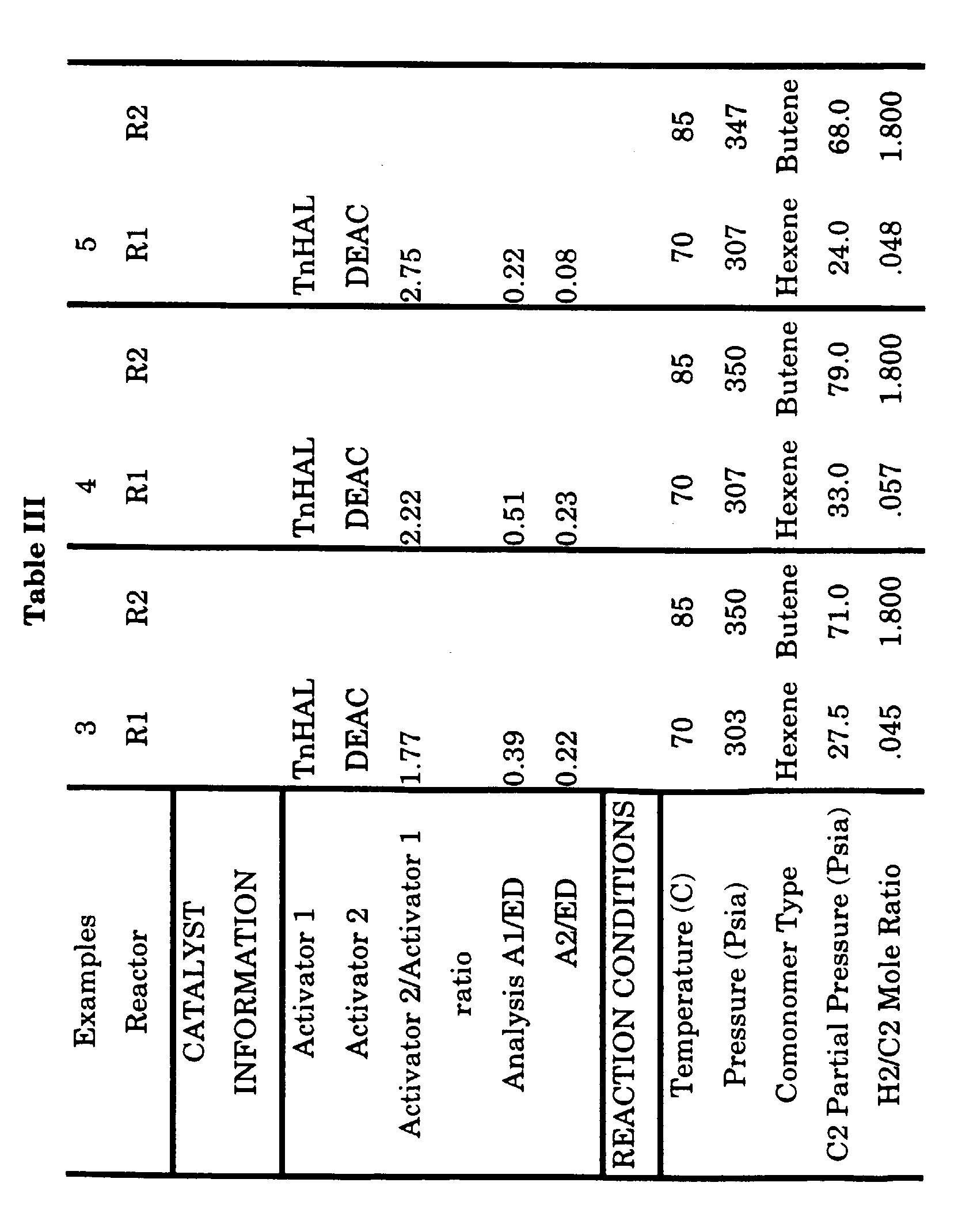
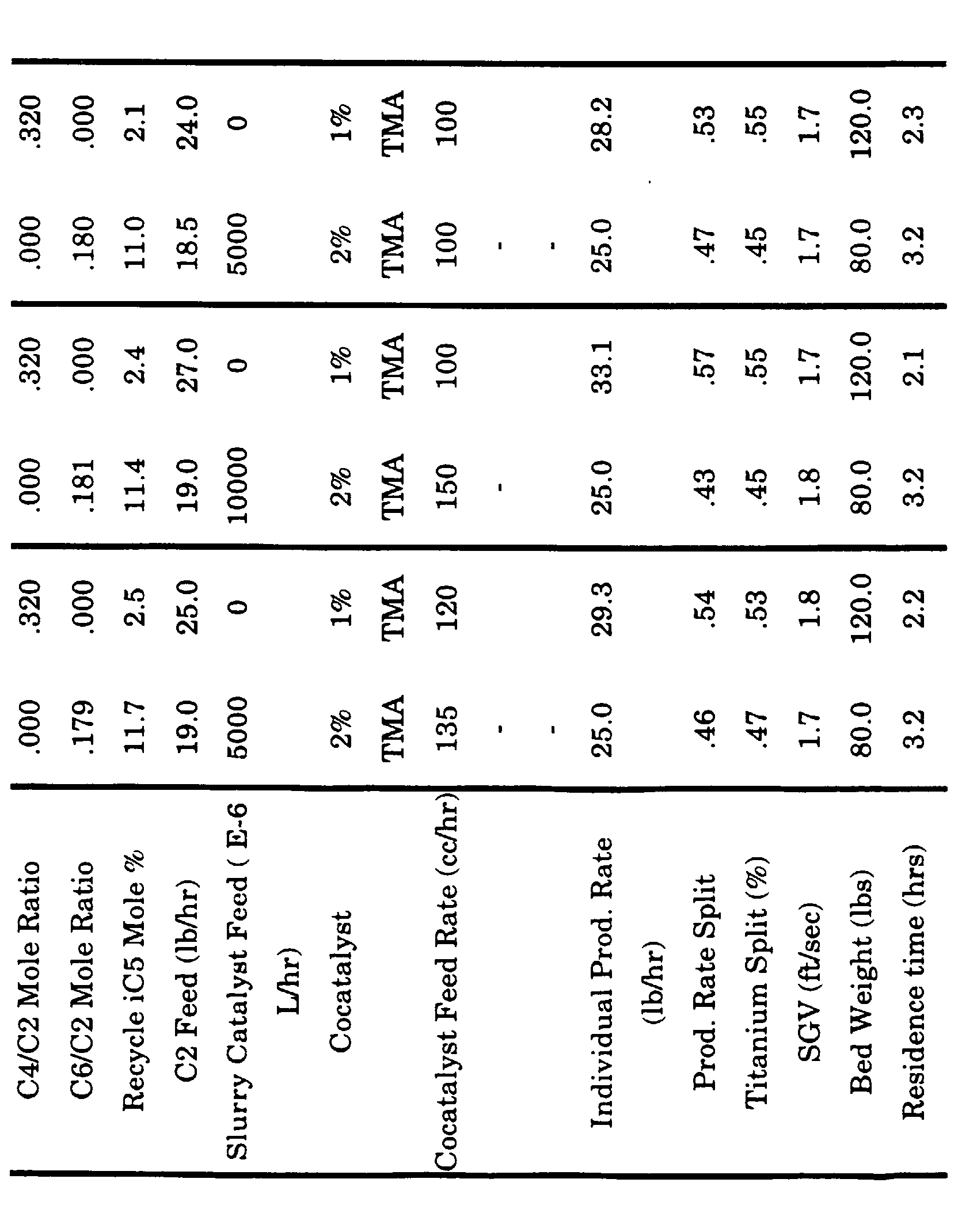
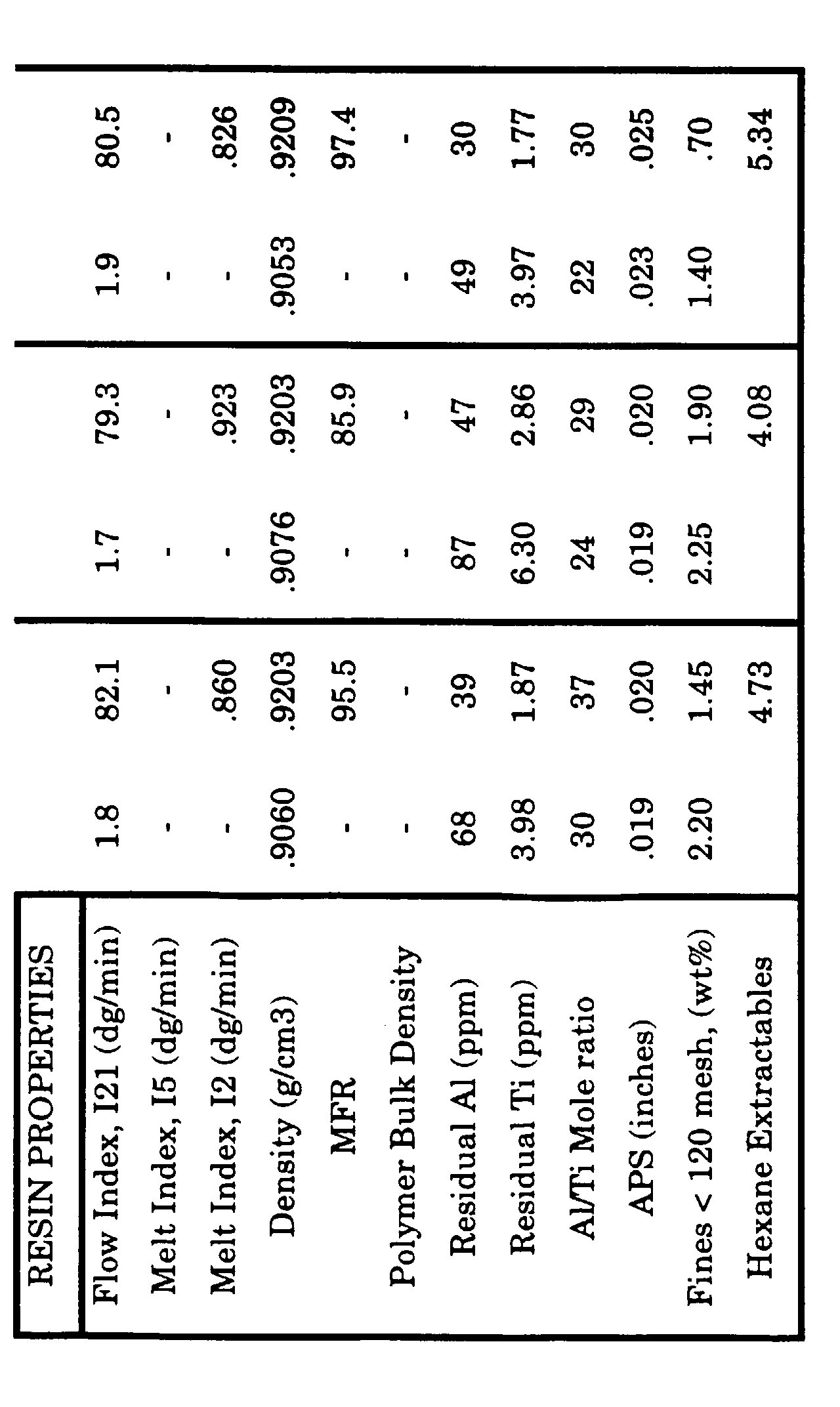


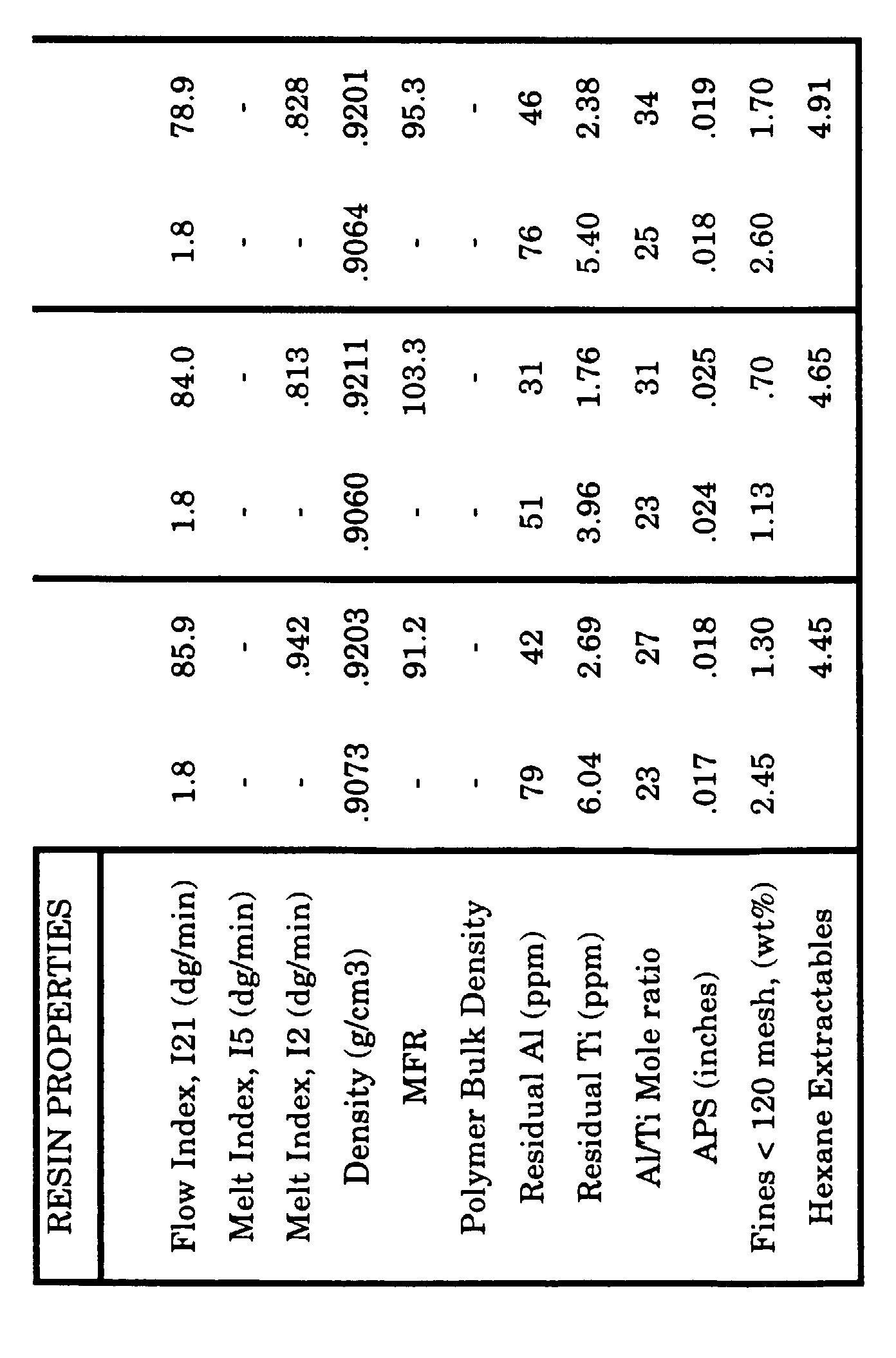
- Varying independently the Activator 1 and Activator 2 molar ratios to the electron donor compound allows manipulation of MFR and polymer bulk density while, at the same time, allowing control of catalyst productivity. Thus, using the invention, one can attain essentially the same MFR at two different sets of activator compound ratios (compare example 3 with example 5) while simultaneously changing the level of hexane extractables. Alternatively, one can use varying Activator 2/Activator 1 mole ratios (independently of the Activator/Electron donor ratio) to significantly change MFR (compare example 6 to example 7). One can also effect absolute hexane extractables levels by manipulating the total Activator (1+2)/Electron Donor ratio (compare example 3 with example 4). Other properties such as bulk density and catalyst productivity can be effected by modifying both the specific activator compound/electron donor mole ratio as well as the total activator/electron donor mole ratio and the Activator 2/Activator 1 mole ratio.
- It is apparent from the examples that the capability to manipulate MFR by in-line control of activator compound/electron donor mole ratios is demonstrated by the invention. Other embodiments of the invention, such as the ability to change polymer bulk density within the reaction system to either increase or decrease residence time within a fixed volume reactor while maintaining constant polymer properties and the ability to modify catalyst productivity while maintaining constant polymer properties are also illustrated by the examples.
-
- 1. Resin properties are those for the final product exiting the reactor, i.e., R1 (first reactor) resin properties are those of the resin exiting R1 into R2 (second reactor) and R2 resin properties represent the total output from the R2 reactor, i.e., the blend.
- 2. Titanium split = the fraction of the total product produced in the first and second reactors based on titanium catalyst residue.
- 3. Prod. Rate Split = the fraction of the total product produced in the first and second reactors based on a production rate calculation and actual production rate from the second reactor
- 3. SGV = superficial gas velocity reported in feet per second.
- 4. Production rate = pounds of resin per hour.
- 5. Density is measured by producing a plaque in accordance with ASTM D-1928, procedure C, and then testing as is via ASTM D-1505. The density is reported in gram per cubic centimeter.
- 6. C2 PP = ethylene partial pressure.
- 7. iC5 = isopentane
- 8. Mlbs = 1000 pounds
- 9. % Condensing = weight percent of total recycle gas with condenses in the cycle gas cooler
- 10. APS = average particle size in inches.
- 11. ED = electron donor
- 12. E-6 L/hr = 10-6 liters/hour or microliters/hour
- 13. comp split = production rate split calculated by heat balance by process control computer.
- 14. Added Al/Ti = mole ratio of cocatalyst to titanium.
-
Claims (9)
- A process for the in situ blending of polymers comprising contacting ethylene and one or more comonomers in two or more fluidized bed reactors connected in series, under polymerization conditions, with a catalyst system comprising (i) a supported or unsupported magnesium/titanium based precursor containing an electron donor and (ii) a hydrocarbyl aluminum cocatalyst in sufficient amount to complete the activation of the precursor, which comprises:with the following provisos:(A) increasing or decreasing the melt flow ratio and/or molecular weight of the blend by, respectively, decreasing or increasing the mole ratio of a precursor activator compound to the electron donor; or(B) increasing or decreasing the bulk density of the blend by, respectively, increasing or decreasing the mole ratio of a precursor activator compound to the electron donor(I) the mole ratio of the precursor activator compound to the electron donor is in the range of 0.1:1 to 1:1.(II) the precursor activator compound can be one compound or a sequential mixture of two different compounds;(III)each precursor activator compound has the formula M(Rn)X(3-n) wherein M is Al or B; each X is independently chlorine, bromine, or iodine; each R is independently a saturated aliphatic hydrocarbon radical having 1 to 14 carbon atoms, provided that when M is Al, n is 1 to 3 and when M is B, n is 0 to 1.5;(IV) the activation of the precursor is carried out prior to the introduction of the precursor into the reactor; and(V) the activation in proviso (IV) is partial.
- The process defined in claim 1 wherein, in each precursor activator compound, the R radical is methyl, ethyl, n-butyl, isobutyl, n-hexyl or n-octyl; and n, when M is aluminum, is 1, 1.5, 2 or 3 and, when M is boron, is 0, 1, or 1.5.
- The process defined in claim 1 or 2 wherein each catalyst activator compound is selected from the group consisting of triethyl aluminum, tri-n-butyl aluminum, tri-n-hexyl aluminum, tri-n-octyl aluminum, triisobutyl aluminum, tri-methyl aluminum, diethyl aluminum chloride, dimethyl aluminum chloride, diisobutyl aluminum chloride, boron trichloride, and ethyl boron dichloride.
- The process defined in any one of the preceding claims wherein the precursor activator compound is a sequential mixture of tri-n-hexylaluminum and diethylaluminum chloride; triethylaluminum and diethylaluminum chloride; or trimethylaluminum and dimethylaluminum chloride.
- The process defined in any one of the preceding claims wherein there are two reactors and, after partial activation of the precursor,(a) ethylene is introduced into each reactor and one or more comonomers are introduced into at least one of the reactors;(b) the mixture of ethylene polymer matrix and active precursor formed in the first reactor in the series is transferred to the second reactor in the series;(c) other than the active precursor referred to in step (b), no additional precursor is introduced into the second reactor;(d) in the reactor in which a low melt or flow index copolymer is made;(1) subject to step (a), alpha-olefin is optionally present in a ratio of 0.01 to 0.8 mole of alpha-olefin per mole of ethylene; and(2) optionally, hydrogen is present in a ratio of 0.001 to 0.3 mole of hydrogen per mole of ethylene; and(e) in the reactor in which a high melt or flow index polymer is made:(1) subject to step (a), alpha-olefin is optionally present in a ratio of 0.005 to 0.6 mole of alpha-olefin per mole of ethylene; and(2) optionally, hydrogen is present in a ratio of 0.2 to 3 moles of hydrogen per mole of ethylene.
- The process defined in any one of the preceding claims wherein the hydrocarbyl aluminum cocatalyst has the formulae R3Al or R2AlX wherein each R is independently alkyl, cycloalkyl, aryl, or hydrogen; at least one R is hydrocarbyl; each hydrocarbyl has 1 to 20 carbon atoms; two or three R radicals can be joined to form a heterocyclic structure; and X is chlorine, bromine, or iodine.
- The process defined in any one of the preceding claims wherein the polymer formed in one reactor has a flow index in the range of 0.01 to 50 grams per 10 minutes and a density in the range of 0.860 to 0.940 gram per cubic centimeter and the polymer formed in the other reactor has a melt index in the range of 5 to 3000 grams per 10 minutes and a density in the range of 0.900 to 0.975 gram per cubic centimeter, the weight ratio of the high molecular weight copolymer to the low molecular weight polymer being in the range of 30:70 to 80:20.
- A process for the in situ blending of polymers comprising contacting ethylene and one or more comonomers in two or more fluidized bed reactors connected in series, under polymerization conditions, with a catalyst system comprising (i) a supported or unsupported magnesium/titanium based precursor containing an electron donor and (ii) a hydrocarbyl aluminum cocatalyst in sufficient amount to complete the activation of the precursor, which comprises increasing or decreasing the melt flow ratio and/or molecular weight of the blend by, respectively, increasing or decreasing the molar ratio of a second precursor activator compound to a first precursor activator compound with the following provisos:(I) the mole ratio of the second precursor activator compound to first precursor activator compound is in the range of 1:1 to 6:1.(II)the two precursor activator compounds are a sequential mixture wherein the first precursor activator compound is the first in the sequence and the second precursor activator compound is the second in the sequence.(III)each precursor activator compound has the formula M(Rn)X(3-n) wherein M is Al or B; each X is independently chlorine, bromine, or iodine; each R is independently a saturated aliphatic hydrocarbon radical having 1 to 14 carbon atoms; and n is 1 to 3;(IV) the activation of the precursor is carried out prior to the introduction of the precursor into the reactor; and(V) the activation in proviso (IV) is partial.
- The process defined in claim 8 wherein each mixture of second precursor activator compound and first precursor activator compound is selected from the group consisting, respectively, of a trihexylaluminum and diethylaluminum chloride; triethyl aluminum and diethylaluminum chloride; diethylaluminum chloride and triethyl aluminum; and diethylaluminum chloride and tri-n-hexylaluminum.
Applications Claiming Priority (2)
| Application Number | Priority Date | Filing Date | Title |
|---|---|---|---|
| US326083 | 1981-11-30 | ||
| US09/326,083 US6187866B1 (en) | 1999-06-04 | 1999-06-04 | Staged reactor process |
Publications (2)
| Publication Number | Publication Date |
|---|---|
| EP1057834A1 true EP1057834A1 (en) | 2000-12-06 |
| EP1057834B1 EP1057834B1 (en) | 2006-03-29 |
Family
ID=23270748
Family Applications (1)
| Application Number | Title | Priority Date | Filing Date |
|---|---|---|---|
| EP00304432A Expired - Lifetime EP1057834B1 (en) | 1999-06-04 | 2000-05-25 | Staged reactor polymerization process |
Country Status (9)
| Country | Link |
|---|---|
| US (1) | US6187866B1 (en) |
| EP (1) | EP1057834B1 (en) |
| JP (1) | JP3684324B2 (en) |
| AT (1) | ATE321790T1 (en) |
| AU (1) | AU3647300A (en) |
| BR (1) | BR0002576A (en) |
| CA (1) | CA2311115A1 (en) |
| DE (1) | DE60026935T2 (en) |
| ES (1) | ES2261153T3 (en) |
Cited By (7)
| Publication number | Priority date | Publication date | Assignee | Title |
|---|---|---|---|---|
| WO2003102075A1 (en) * | 2002-06-04 | 2003-12-11 | Union Carbide Chemicals & Plastics Technology Corporation | Polymer compositions and method of making pipes thereof |
| EP1764390A1 (en) * | 2002-06-04 | 2007-03-21 | Union Carbide Chemicals & Plastics Technology Corporation | Polymer compositions and method of making pipes thereof |
| WO2009080359A1 (en) * | 2007-12-24 | 2009-07-02 | Basell Polyolefine Gmbh | Multistage process for the polymerization of olefins |
| EP2246372A1 (en) * | 2009-04-30 | 2010-11-03 | Borealis AG | Improved multi-stage process for producing multi-modal linear low density polyethylene |
| EP2246368A1 (en) * | 2009-04-30 | 2010-11-03 | Borealis AG | Improved ethylene polymerization catalyst composition |
| RU2464282C2 (en) * | 2007-03-06 | 2012-10-20 | ИНЕОС ЮЭсЭй ЭлЭлСи | Olefin polymerisation method |
| WO2012152775A1 (en) | 2011-05-10 | 2012-11-15 | Basell Polyolefine Gmbh | A process for homogenizing and pelletizing a polyethylene composition |
Families Citing this family (53)
| Publication number | Priority date | Publication date | Assignee | Title |
|---|---|---|---|---|
| US6630544B1 (en) * | 2002-04-18 | 2003-10-07 | Equistar Chemicals, Lp | Propylene polymerization process with enhanced catalyst activity |
| MXPA05012158A (en) * | 2003-05-12 | 2006-02-10 | Union Carbide Chem Plastic | Process for control of polymer fines in a gas-phase polymerization. |
| TW200504093A (en) | 2003-05-12 | 2005-02-01 | Dow Global Technologies Inc | Polymer composition and process to manufacture high molecular weight-high density polyethylene and film therefrom |
| AU2004247640B2 (en) * | 2003-05-30 | 2009-12-24 | Univation Technologies, Llc | Gas phase polymerization and method of controlling same |
| WO2005058982A1 (en) * | 2003-12-19 | 2005-06-30 | Basell Polyolefine Gmbh | Process for the (co)polymerization of ethylene |
| DE602005020018D1 (en) | 2004-07-07 | 2010-04-29 | Dow Global Technologies Inc | MULTILAYER PROCESS FOR PREPARING ETHYLENE POLYMER COMPOSITIONS |
| BRPI0515025B1 (en) | 2004-08-09 | 2019-02-05 | Union Carbide Chem Plastic | ziegler-natta procatalyst composition |
| JP2008509277A (en) * | 2004-08-09 | 2008-03-27 | ダウ グローバル テクノロジーズ インコーポレイティド | Supported bis (hydroxyarylaryloxy) catalysts for the production of polymers |
| WO2006020623A1 (en) | 2004-08-09 | 2006-02-23 | Union Carbide Chemicals & Plastics Technology Corporation | Robust spray-dried ziegler-natta procatalyst and polymerization process employing same |
| JP2006096972A (en) * | 2004-08-31 | 2006-04-13 | Sumitomo Chemical Co Ltd | Process for producing olefin polymer |
| AU2005316788B2 (en) | 2004-12-17 | 2012-04-05 | Dow Global Technologies Llc | Rheology modified polyethylene compositions |
| US7629422B2 (en) | 2004-12-21 | 2009-12-08 | Univation Technologies, Llc | Process for transitioning between Ziegler-Natta-based and chromium-based catalysts |
| JP4462073B2 (en) * | 2005-03-08 | 2010-05-12 | 株式会社デンソー | Electronic throttle control device for vehicle internal combustion engine |
| MX2008012969A (en) * | 2006-04-07 | 2008-12-17 | Dow Global Technologies Inc | Polyolefin compositions, articles made therefrom and methods for preparing the same. |
| WO2007130553A2 (en) | 2006-05-02 | 2007-11-15 | Dow Global Technologies Inc. | High-density polyethylene compositions, method of making the same, wire and cable jackets made therefrom, and method of making such wire and cable jackets |
| US7456244B2 (en) * | 2006-05-23 | 2008-11-25 | Dow Global Technologies | High-density polyethylene compositions and method of making the same |
| EP2267070B1 (en) | 2006-10-23 | 2012-06-20 | Dow Global Technologies LLC | Method of making polyethylene compositions |
| EP2052026B2 (en) * | 2007-05-02 | 2021-07-14 | Dow Global Technologies LLC | High-density polyethylene compositions, method of making the same, injection molded articles made therefrom, and method of making such articles |
| EP2003151A1 (en) | 2007-06-15 | 2008-12-17 | Nova Chemicals Corporation | Improved hydrogen response through catalyst modification |
| JP5378408B2 (en) * | 2007-12-31 | 2013-12-25 | ダウ グローバル テクノロジーズ エルエルシー | Ethylene-based polymer composition, method for producing the composition |
| JP5972574B2 (en) | 2008-08-06 | 2016-08-17 | ユニオン カーバイド ケミカルズ アンド プラスティックス テクノロジー エルエルシー | Ziegler-Natta catalyst composition for making polyethylene with high molecular weight tail and method of making the same |
| US8604142B2 (en) | 2009-01-23 | 2013-12-10 | Evonik Oxeno Gmbh | Polyolefin gas phase polymerization with 3-substituted C4-10-alkene |
| JP5583142B2 (en) | 2009-01-23 | 2014-09-03 | エボニック デグサ ゲーエムベーハー | PE M1B film ZN / CR |
| CN102361925B (en) | 2009-01-30 | 2013-08-14 | 陶氏环球技术有限责任公司 | High-density polyethylene compositions, method of producing the same, closure devices made therefrom, and method of making such closure devices |
| ES2589142T3 (en) | 2009-11-23 | 2016-11-10 | Dow Global Technologies Llc | Compositions, films and methods to prepare them |
| JP5137984B2 (en) | 2010-02-12 | 2013-02-06 | 株式会社日立ハイテクインスツルメンツ | Field network system |
| CA2793693A1 (en) | 2010-04-05 | 2011-10-13 | Dow Global Technologies Llc | Process for polymerizing olefin-based polymers containing high molecular weight fractions in condensed and super-condensed mode |
| US8809220B2 (en) | 2010-04-13 | 2014-08-19 | Union Carbide Chemicals & Plastics Technology Llc | Method of making Ziegler-Natta type catalysts |
| WO2011130420A1 (en) | 2010-04-14 | 2011-10-20 | Dow Global Technologies Llc | Fuel containers made from polyethylene compositions with improved creep resistance |
| US20120053305A1 (en) * | 2010-08-24 | 2012-03-01 | Equistar Chemicals, Lp | Preparation of LLDPE having controlled xylene solubles or hexane extractables |
| US9221932B2 (en) | 2010-08-31 | 2015-12-29 | Union Carbide Chemicals & Plastics Technology Llc | Ziegler-Natta type catalysts, methods of preparing same, polymers produced using the catalysts and articles produced therefrom |
| SG191342A1 (en) | 2010-12-31 | 2013-08-30 | Union Carbide Chem Plastic | Polymers, method of producing the same, and articles made therefrom |
| EP2658883B1 (en) | 2010-12-31 | 2015-07-22 | Union Carbide Chemicals & Plastics Technology LLC | Control of resin molecular weight distribution using mixed catalyst systems |
| US8653208B2 (en) | 2012-05-18 | 2014-02-18 | Union Carbide Chemicals & Plastics Technology Llc | Process for preparing catalysts and catalysts made thereby |
| WO2014043364A1 (en) | 2012-09-13 | 2014-03-20 | Dow Global Technologies Llc | Ethylene-based polymer compositions, and articles prepared from the same |
| US9376511B2 (en) * | 2013-03-13 | 2016-06-28 | Chevron Phillips Chemical Company Lp | Polymerization catalysts and polymers |
| WO2014209930A1 (en) | 2013-06-29 | 2014-12-31 | Dow Global Technologies Llc | A polyethylene composition and process for polymerizing the same |
| WO2015026731A1 (en) | 2013-08-19 | 2015-02-26 | Dow Global Technologies Llc | Method for producing an ethylene based polymer in a polymerisation process using a self-limiting agent |
| US10155831B2 (en) * | 2013-09-05 | 2018-12-18 | Univation Technologies, Llc | Process control for long chain branching control in polyethylene production |
| CN105705528B (en) | 2013-11-15 | 2018-11-09 | 陶氏环球技术有限责任公司 | Polyolefin composition and method of producing same |
| US10370527B2 (en) | 2014-12-11 | 2019-08-06 | Dow Global Technologies Llc | Polyethylene compositions having living hinge properties |
| CN110546174A (en) * | 2017-05-12 | 2019-12-06 | 巴塞尔聚烯烃意大利有限公司 | Method for activating ethylene polymerization catalyst |
| JP7304348B2 (en) * | 2017-12-05 | 2023-07-06 | ユニベーション・テクノロジーズ・エルエルシー | Activated spray-dried Ziegler-Natta catalyst system |
| AR114620A1 (en) | 2017-12-15 | 2020-09-30 | Dow Global Technologies Llc | FORMULATION CONTAINING A HIGH-DENSITY POLYETHYLENE COMPOSITION AND MICRO-IRRIGATION DRIP TAPE CONTAINING IT |
| WO2020025757A1 (en) | 2018-08-02 | 2020-02-06 | Borealis Ag | Process for polymerizing ethylene in a multi-stage polymerization process |
| AR119038A1 (en) | 2019-06-11 | 2021-11-17 | Dow Global Technologies Llc | INJECTION MOLDED CAPS OR CLOSURES AND METHODS OF THESE |
| CN114729074A (en) | 2019-09-18 | 2022-07-08 | 格雷斯公司 | Catalyst composition for polyolefin polymers |
| JP7539785B2 (en) * | 2020-03-31 | 2024-08-26 | 住友化学株式会社 | Solid catalyst components for olefin polymerization |
| EP4263701B1 (en) | 2020-12-21 | 2024-10-09 | Dow Global Technologies LLC | Polyethylene compositions for closure applications |
| CN116670225A (en) | 2021-01-29 | 2023-08-29 | 陶氏环球技术有限责任公司 | Thermoplastic compositions comprising bimodal polyethylene and articles made therefrom |
| AR128480A1 (en) | 2022-02-11 | 2024-05-15 | Dow Global Technologies Llc | BIMODAL MEDIUM DENSITY POLYETHYLENE COMPOSITIONS |
| WO2026072196A1 (en) | 2024-09-30 | 2026-04-02 | Dow Global Technologies Llc | Multimodal polyethylene compositions |
| WO2026072195A1 (en) | 2024-09-30 | 2026-04-02 | Dow Global Technologies Llc | Multimodal polyethylene compositions |
Citations (5)
| Publication number | Priority date | Publication date | Assignee | Title |
|---|---|---|---|---|
| EP0528523A1 (en) * | 1991-07-24 | 1993-02-24 | Mobil Oil Corporation | Improved ethylene polymer film resins |
| EP0533452A1 (en) * | 1991-03-21 | 1993-03-24 | Mobil Oil Corporation | Production of bimodal ethylene polymers in tandem reactors |
| EP0754708A2 (en) * | 1995-07-21 | 1997-01-22 | Union Carbide Chemicals & Plastics Technology Corporation | Process for producing an in situ polyethylene blend |
| EP0778289A1 (en) * | 1991-03-06 | 1997-06-11 | Mobil Oil Corporation | Process for producing bimodal ethylene polymers in tandem reactors |
| EP0794200A2 (en) * | 1996-03-05 | 1997-09-10 | Union Carbide Chemicals & Plastics Technology Corporation | Staged reactor polymerisation process |
Family Cites Families (2)
| Publication number | Priority date | Publication date | Assignee | Title |
|---|---|---|---|---|
| US5126398A (en) | 1988-11-16 | 1992-06-30 | Union Carbide Chemicals & Plastics Technology Corporation | Process for the in situ blending of polymers |
| US5503914A (en) | 1994-07-08 | 1996-04-02 | Union Carbide Chemicals & Plastics Technology Corporation | Film extruded from an in situ blend of ethylene copolymers |
-
1999
- 1999-06-04 US US09/326,083 patent/US6187866B1/en not_active Expired - Lifetime
-
2000
- 2000-05-25 DE DE60026935T patent/DE60026935T2/en not_active Expired - Lifetime
- 2000-05-25 EP EP00304432A patent/EP1057834B1/en not_active Expired - Lifetime
- 2000-05-25 ES ES00304432T patent/ES2261153T3/en not_active Expired - Lifetime
- 2000-05-25 AT AT00304432T patent/ATE321790T1/en not_active IP Right Cessation
- 2000-05-26 AU AU36473/00A patent/AU3647300A/en not_active Abandoned
- 2000-06-02 CA CA002311115A patent/CA2311115A1/en not_active Abandoned
- 2000-06-02 JP JP2000165661A patent/JP3684324B2/en not_active Expired - Fee Related
- 2000-06-02 BR BR0002576-3A patent/BR0002576A/en not_active IP Right Cessation
Patent Citations (5)
| Publication number | Priority date | Publication date | Assignee | Title |
|---|---|---|---|---|
| EP0778289A1 (en) * | 1991-03-06 | 1997-06-11 | Mobil Oil Corporation | Process for producing bimodal ethylene polymers in tandem reactors |
| EP0533452A1 (en) * | 1991-03-21 | 1993-03-24 | Mobil Oil Corporation | Production of bimodal ethylene polymers in tandem reactors |
| EP0528523A1 (en) * | 1991-07-24 | 1993-02-24 | Mobil Oil Corporation | Improved ethylene polymer film resins |
| EP0754708A2 (en) * | 1995-07-21 | 1997-01-22 | Union Carbide Chemicals & Plastics Technology Corporation | Process for producing an in situ polyethylene blend |
| EP0794200A2 (en) * | 1996-03-05 | 1997-09-10 | Union Carbide Chemicals & Plastics Technology Corporation | Staged reactor polymerisation process |
Cited By (14)
| Publication number | Priority date | Publication date | Assignee | Title |
|---|---|---|---|---|
| US7989549B2 (en) | 2002-06-04 | 2011-08-02 | Union Carbide Chemicals & Plastics Technology Llc | Polymer compositions and method of making pipes |
| EP1764390A1 (en) * | 2002-06-04 | 2007-03-21 | Union Carbide Chemicals & Plastics Technology Corporation | Polymer compositions and method of making pipes thereof |
| RU2326904C2 (en) * | 2002-06-04 | 2008-06-20 | Юнион Карбайд Кемикалз Энд Пластикс Текнолоджи Корпорейшн | Polymer compositions and process of tube production |
| WO2003102075A1 (en) * | 2002-06-04 | 2003-12-11 | Union Carbide Chemicals & Plastics Technology Corporation | Polymer compositions and method of making pipes thereof |
| CN100575405C (en) * | 2002-06-04 | 2009-12-30 | 联合碳化化学及塑料技术有限责任公司 | Polymer composition and method of making pipe therefrom |
| RU2464282C2 (en) * | 2007-03-06 | 2012-10-20 | ИНЕОС ЮЭсЭй ЭлЭлСи | Olefin polymerisation method |
| WO2009080359A1 (en) * | 2007-12-24 | 2009-07-02 | Basell Polyolefine Gmbh | Multistage process for the polymerization of olefins |
| WO2010125018A1 (en) * | 2009-04-30 | 2010-11-04 | Borealis Ag | Improved ethylene polymerization catalyst composition |
| WO2010125020A1 (en) * | 2009-04-30 | 2010-11-04 | Borealis Ag | Improved multi-stage process for producing multi-modal linear low density polyethylene |
| EP2246368A1 (en) * | 2009-04-30 | 2010-11-03 | Borealis AG | Improved ethylene polymerization catalyst composition |
| CN102395610A (en) * | 2009-04-30 | 2012-03-28 | 博里利斯股份公司 | Improved multistage process for the production of multimodal linear low density polyethylene |
| EP2246372A1 (en) * | 2009-04-30 | 2010-11-03 | Borealis AG | Improved multi-stage process for producing multi-modal linear low density polyethylene |
| CN102395610B (en) * | 2009-04-30 | 2014-08-13 | 博里利斯股份公司 | Improved multistage process for the production of multimodal linear low density polyethylene |
| WO2012152775A1 (en) | 2011-05-10 | 2012-11-15 | Basell Polyolefine Gmbh | A process for homogenizing and pelletizing a polyethylene composition |
Also Published As
| Publication number | Publication date |
|---|---|
| ES2261153T3 (en) | 2006-11-16 |
| JP2001019707A (en) | 2001-01-23 |
| JP3684324B2 (en) | 2005-08-17 |
| DE60026935T2 (en) | 2006-11-30 |
| EP1057834B1 (en) | 2006-03-29 |
| CA2311115A1 (en) | 2000-12-04 |
| BR0002576A (en) | 2001-01-02 |
| ATE321790T1 (en) | 2006-04-15 |
| AU3647300A (en) | 2000-12-07 |
| DE60026935D1 (en) | 2006-05-18 |
| US6187866B1 (en) | 2001-02-13 |
Similar Documents
| Publication | Publication Date | Title |
|---|---|---|
| US6187866B1 (en) | Staged reactor process | |
| EP0794200B1 (en) | Staged reactor polymerisation process | |
| US6617405B1 (en) | Process for the preparation of polyethylene | |
| US5677375A (en) | Process for producing an in situ polyethylene blend | |
| EP0691367B1 (en) | Film extruded from an in situ blend of ethylene copolymers | |
| US5405901A (en) | Process of producing ethylene polymer blends in gas phase | |
| US6248831B1 (en) | High strength polyethylene film | |
| EP0773258B1 (en) | Film extruded from a blend of ethylene copolymers | |
| EP0533452A1 (en) | Production of bimodal ethylene polymers in tandem reactors | |
| US5744551A (en) | High strength polyethylene film | |
| EP0692515A1 (en) | Film extruded from an in situ blend of ethylene copolymers | |
| US6184299B1 (en) | Staged reactor process | |
| AU708276B2 (en) | High strength polyethylene film | |
| AU730068B2 (en) | A process for preparing an in situ polyethylene blend | |
| WO2000015712A1 (en) | Polyethylene film composition | |
| MXPA97001678A (en) | Great-activity reactor process by stages |
Legal Events
| Date | Code | Title | Description |
|---|---|---|---|
| PUAI | Public reference made under article 153(3) epc to a published international application that has entered the european phase |
Free format text: ORIGINAL CODE: 0009012 |
|
| AK | Designated contracting states |
Kind code of ref document: A1 Designated state(s): AT BE CH CY DE DK ES FI FR GB GR IE IT LI LU MC NL PT SE |
|
| AX | Request for extension of the european patent |
Free format text: AL;LT;LV;MK;RO;SI |
|
| 17P | Request for examination filed |
Effective date: 20010605 |
|
| AKX | Designation fees paid |
Free format text: AT BE CH CY DE DK ES FI FR GB GR IE IT LI LU MC NL PT SE |
|
| 17Q | First examination report despatched |
Effective date: 20031009 |
|
| GRAP | Despatch of communication of intention to grant a patent |
Free format text: ORIGINAL CODE: EPIDOSNIGR1 |
|
| GRAS | Grant fee paid |
Free format text: ORIGINAL CODE: EPIDOSNIGR3 |
|
| GRAA | (expected) grant |
Free format text: ORIGINAL CODE: 0009210 |
|
| AK | Designated contracting states |
Kind code of ref document: B1 Designated state(s): AT BE CH CY DE DK ES FI FR GB GR IE IT LI LU MC NL PT SE |
|
| PG25 | Lapsed in a contracting state [announced via postgrant information from national office to epo] |
Ref country code: CH Free format text: LAPSE BECAUSE OF FAILURE TO SUBMIT A TRANSLATION OF THE DESCRIPTION OR TO PAY THE FEE WITHIN THE PRESCRIBED TIME-LIMIT Effective date: 20060329 Ref country code: AT Free format text: LAPSE BECAUSE OF FAILURE TO SUBMIT A TRANSLATION OF THE DESCRIPTION OR TO PAY THE FEE WITHIN THE PRESCRIBED TIME-LIMIT Effective date: 20060329 Ref country code: LI Free format text: LAPSE BECAUSE OF FAILURE TO SUBMIT A TRANSLATION OF THE DESCRIPTION OR TO PAY THE FEE WITHIN THE PRESCRIBED TIME-LIMIT Effective date: 20060329 |
|
| REG | Reference to a national code |
Ref country code: GB Ref legal event code: FG4D |
|
| RIN1 | Information on inventor provided before grant (corrected) |
Inventor name: UPHAM, STEPHANIE MARIE Inventor name: MADDEN, JAMES DANIEL Inventor name: MICHIE, WILLIAM JAMES, JR. Inventor name: JORGENSEN, ROBERT JAMES |
|
| REG | Reference to a national code |
Ref country code: CH Ref legal event code: EP |
|
| REG | Reference to a national code |
Ref country code: IE Ref legal event code: FG4D |
|
| REF | Corresponds to: |
Ref document number: 60026935 Country of ref document: DE Date of ref document: 20060518 Kind code of ref document: P |
|
| PG25 | Lapsed in a contracting state [announced via postgrant information from national office to epo] |
Ref country code: IE Free format text: LAPSE BECAUSE OF NON-PAYMENT OF DUE FEES Effective date: 20060525 |
|
| PG25 | Lapsed in a contracting state [announced via postgrant information from national office to epo] |
Ref country code: MC Free format text: LAPSE BECAUSE OF NON-PAYMENT OF DUE FEES Effective date: 20060531 |
|
| REG | Reference to a national code |
Ref country code: SE Ref legal event code: TRGR |
|
| PG25 | Lapsed in a contracting state [announced via postgrant information from national office to epo] |
Ref country code: DK Free format text: LAPSE BECAUSE OF FAILURE TO SUBMIT A TRANSLATION OF THE DESCRIPTION OR TO PAY THE FEE WITHIN THE PRESCRIBED TIME-LIMIT Effective date: 20060629 |
|
| PG25 | Lapsed in a contracting state [announced via postgrant information from national office to epo] |
Ref country code: PT Free format text: LAPSE BECAUSE OF FAILURE TO SUBMIT A TRANSLATION OF THE DESCRIPTION OR TO PAY THE FEE WITHIN THE PRESCRIBED TIME-LIMIT Effective date: 20060829 |
|
| ET | Fr: translation filed | ||
| REG | Reference to a national code |
Ref country code: CH Ref legal event code: PL |
|
| REG | Reference to a national code |
Ref country code: ES Ref legal event code: FG2A Ref document number: 2261153 Country of ref document: ES Kind code of ref document: T3 |
|
| PLBE | No opposition filed within time limit |
Free format text: ORIGINAL CODE: 0009261 |
|
| STAA | Information on the status of an ep patent application or granted ep patent |
Free format text: STATUS: NO OPPOSITION FILED WITHIN TIME LIMIT |
|
| 26N | No opposition filed |
Effective date: 20070102 |
|
| PG25 | Lapsed in a contracting state [announced via postgrant information from national office to epo] |
Ref country code: GR Free format text: LAPSE BECAUSE OF FAILURE TO SUBMIT A TRANSLATION OF THE DESCRIPTION OR TO PAY THE FEE WITHIN THE PRESCRIBED TIME-LIMIT Effective date: 20060630 |
|
| PG25 | Lapsed in a contracting state [announced via postgrant information from national office to epo] |
Ref country code: FI Free format text: LAPSE BECAUSE OF FAILURE TO SUBMIT A TRANSLATION OF THE DESCRIPTION OR TO PAY THE FEE WITHIN THE PRESCRIBED TIME-LIMIT Effective date: 20060329 |
|
| PG25 | Lapsed in a contracting state [announced via postgrant information from national office to epo] |
Ref country code: LU Free format text: LAPSE BECAUSE OF NON-PAYMENT OF DUE FEES Effective date: 20060525 |
|
| PG25 | Lapsed in a contracting state [announced via postgrant information from national office to epo] |
Ref country code: CY Free format text: LAPSE BECAUSE OF FAILURE TO SUBMIT A TRANSLATION OF THE DESCRIPTION OR TO PAY THE FEE WITHIN THE PRESCRIBED TIME-LIMIT Effective date: 20060329 |
|
| PGFP | Annual fee paid to national office [announced via postgrant information from national office to epo] |
Ref country code: GB Payment date: 20090520 Year of fee payment: 10 |
|
| GBPC | Gb: european patent ceased through non-payment of renewal fee |
Effective date: 20100525 |
|
| PG25 | Lapsed in a contracting state [announced via postgrant information from national office to epo] |
Ref country code: GB Free format text: LAPSE BECAUSE OF NON-PAYMENT OF DUE FEES Effective date: 20100525 |
|
| PGFP | Annual fee paid to national office [announced via postgrant information from national office to epo] |
Ref country code: ES Payment date: 20120607 Year of fee payment: 13 |
|
| PGFP | Annual fee paid to national office [announced via postgrant information from national office to epo] |
Ref country code: SE Payment date: 20130513 Year of fee payment: 14 Ref country code: DE Payment date: 20130522 Year of fee payment: 14 |
|
| PGFP | Annual fee paid to national office [announced via postgrant information from national office to epo] |
Ref country code: FR Payment date: 20130531 Year of fee payment: 14 Ref country code: IT Payment date: 20130514 Year of fee payment: 14 Ref country code: NL Payment date: 20130510 Year of fee payment: 14 Ref country code: BE Payment date: 20130531 Year of fee payment: 14 |
|
| REG | Reference to a national code |
Ref country code: DE Ref legal event code: R119 Ref document number: 60026935 Country of ref document: DE |
|
| REG | Reference to a national code |
Ref country code: NL Ref legal event code: V1 Effective date: 20141201 |
|
| PG25 | Lapsed in a contracting state [announced via postgrant information from national office to epo] |
Ref country code: SE Free format text: LAPSE BECAUSE OF NON-PAYMENT OF DUE FEES Effective date: 20140526 |
|
| REG | Reference to a national code |
Ref country code: SE Ref legal event code: EUG |
|
| REG | Reference to a national code |
Ref country code: DE Ref legal event code: R119 Ref document number: 60026935 Country of ref document: DE Effective date: 20141202 |
|
| PG25 | Lapsed in a contracting state [announced via postgrant information from national office to epo] |
Ref country code: NL Free format text: LAPSE BECAUSE OF NON-PAYMENT OF DUE FEES Effective date: 20141201 |
|
| REG | Reference to a national code |
Ref country code: FR Ref legal event code: ST Effective date: 20150130 |
|
| PG25 | Lapsed in a contracting state [announced via postgrant information from national office to epo] |
Ref country code: DE Free format text: LAPSE BECAUSE OF NON-PAYMENT OF DUE FEES Effective date: 20141202 Ref country code: IT Free format text: LAPSE BECAUSE OF NON-PAYMENT OF DUE FEES Effective date: 20140525 |
|
| PG25 | Lapsed in a contracting state [announced via postgrant information from national office to epo] |
Ref country code: FR Free format text: LAPSE BECAUSE OF NON-PAYMENT OF DUE FEES Effective date: 20140602 |
|
| REG | Reference to a national code |
Ref country code: ES Ref legal event code: FD2A Effective date: 20150629 |
|
| PG25 | Lapsed in a contracting state [announced via postgrant information from national office to epo] |
Ref country code: ES Free format text: LAPSE BECAUSE OF NON-PAYMENT OF DUE FEES Effective date: 20140526 |
|
| PG25 | Lapsed in a contracting state [announced via postgrant information from national office to epo] |
Ref country code: BE Free format text: LAPSE BECAUSE OF NON-PAYMENT OF DUE FEES Effective date: 20140531 |