EP1057693B1 - Electrochromic anti-glare mirror - Google Patents
Electrochromic anti-glare mirror Download PDFInfo
- Publication number
- EP1057693B1 EP1057693B1 EP00111410A EP00111410A EP1057693B1 EP 1057693 B1 EP1057693 B1 EP 1057693B1 EP 00111410 A EP00111410 A EP 00111410A EP 00111410 A EP00111410 A EP 00111410A EP 1057693 B1 EP1057693 B1 EP 1057693B1
- Authority
- EP
- European Patent Office
- Prior art keywords
- electrochromic
- glare
- circuit board
- electrochromic anti
- heater
- Prior art date
- Legal status (The legal status is an assumption and is not a legal conclusion. Google has not performed a legal analysis and makes no representation as to the accuracy of the status listed.)
- Expired - Lifetime
Links
Images




Classifications
-
- B—PERFORMING OPERATIONS; TRANSPORTING
- B60—VEHICLES IN GENERAL
- B60R—VEHICLES, VEHICLE FITTINGS, OR VEHICLE PARTS, NOT OTHERWISE PROVIDED FOR
- B60R1/00—Optical viewing arrangements; Real-time viewing arrangements for drivers or passengers using optical image capturing systems, e.g. cameras or video systems specially adapted for use in or on vehicles
- B60R1/02—Rear-view mirror arrangements
- B60R1/08—Rear-view mirror arrangements involving special optical features, e.g. avoiding blind spots, e.g. convex mirrors; Side-by-side associations of rear-view and other mirrors
- B60R1/083—Anti-glare mirrors, e.g. "day-night" mirrors
- B60R1/088—Anti-glare mirrors, e.g. "day-night" mirrors using a cell of electrically changeable optical characteristic, e.g. liquid-crystal or electrochromic mirrors
Definitions
- the present invention relates to an electrochromic anti-glare mirror for electrically iron reflectance when connected to a power supply with the features of first part of claim 1 as known from US 5820245 A .
- electrochromic anti-glare mirrors in which an electrochromic film provided on a rear surface side of a substrate glass is made to color electrically such that the brightness of reflected light can be adjusted.
- a transparent conductive film is provided on the rear surface of the substrate glass, and, on the rear surface of the transparent conductive film, an electrochromic film is provided.
- a reflective conductive film made of aluminum or the like is provided on the rear surface of the electrochromic film.
- An electrochromic layer is formed by the transparent conductive film, electrochromic film, and the reflective conductive film.
- a protective plate made of glass, a metal, or the like is adhered by an adhesive for sealing to the rear surface of this electrochromic layer, and the electrochromic layer is protected by this protective plate.
- the electrochromic anti-glare mirror has a pair of electrochromic anti-glare terminals.
- One of the electrochromic anti-glare terminals contacts the substrate glass and the transparent conductive film, whereas the other electrochromic anti-glare terminal contacts the substrate glass and the reflective conductive film.
- the wires, to this pair of the electrochromic anti-glare terminals, for energizing the electrochromic film between the transparent conductive film and the reflective conductive film are cords (These wires will be referred to hereinafter as “the wires for electrochromic anti-glare").
- a pair of electrodes (referred to hereinafter as “electrochromic anti-glare electrodes”) are connected to these wires for electrochromic anti-glare.
- the electrochromic film between the transparent conductive film and the reflective conductive film is energized, and the electrochromic film is electrically made to color. In this way, the brightness of the light reflected by the electrochromic anti-glare mirror is adjusted.
- a fail-safe resistor is connected within the cord complete of the wires for electrochromic anti-glare.
- the fail-safe resistor discharges the electric charges of the electrochromic film between the transparent conductive film and the reflective conductive film. In this way, the fail-safe resistor does not allow the electrochromic film to color, and acts to forcibly return the electrochromic anti-glare mirror to a mode for day time.
- a heater is provided on the rear surface of the protective plate.
- a pair of heater terminals are provided at the heater, and the heater generates heat by being energized.
- the wires to the heater terminals (hereinafter referred to as the "wires for the heater") for energizing the heater are cords.
- a pair of electrodes (referred to as “the heater electrodes”, hereinafter) are connected to the wires for the heater. By supplying electric power from this pair of heater electrodes to the heater through the wires, the heater is energized and generates heat. In this way, the heater heats the substrate glass and fog on the electrochromic anti-glare mirror is eliminated.
- the resistor for fail-safe is wires within the cord complete of the wires for electrochromic anti-glare and a process of winding waterproof tape around this resistor for fail-safe is needed, the number of components and work processes increase, and as a result, the cost becomes high.
- US 5820245 A and US 5659423 A disclose an electrochromic anti-glare mirror with the features of first part of claim 1.
- US 5504478 A discloses an electrochromic anti-glare mirror wherein the circuit board includes two types of conductors having polarities different from each other for supplying electric power to the electrochromic layer.
- an object of the present invention is to obtain an electrochromic anti-glare mirror in which, by using a circuit board as the wiring for making an electrochromic film generate color electrically, incorrect assembly can be prevented and assemblability is improved, and, therefore, the number of the work processes decreases and the cost can be reduced.
- An electrochromic anti-glare mirror according to the present invention includes the features of claim 1.
- the subject matter of sub-claims are preferred embodiments.
- a conductor for energizing an electrochromic film is provided on a circuit board, and electric power is supplied to the electrochromic film through the conductor.
- the electrochromic film is thereby energized and made to color electrically. In this way, brightness of light reflected by the electrochromic anti-glare mirror is adjusted.
- the conductor is provided at the circuit board, there is no need for complicated work for installing and connecting cords as there is in the conventional structure in which the wires are cords. Therefore, not only can incorrect assembly be prevented, but also, assemblability can be improved and the number of work processes can be reduced, thereby reducing costs. Further, since the conductor can be made thin, the electrochromic anti-glare mirror can be made thinner and requires less space. Moreover, since the conductor is fixed to the circuit board by printing or the like, catching of the wire for electrochromic anti-glare on the other portions of the structure at the time of mirror adjustment can be suppressed.
- the material of this transparent substrate is not limited to glass, and plastic may be used for example.
- the technique for providing the conductor on the circuit board may be any technique such as printing, etching, adhesion, or the like.
- the reflective film may be provided separately from the electrochromic layer.
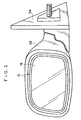
- FIG. 1 a main portion of an electrochromic anti-glare mirror 10 which relates to an embodiment of the present invention is illustrated in rear view, and in Fig. 2, the exterior of the electrochromic anti-glare mirror 10 is illustrated in front view. Moreover, in Fig. 3, the schematic structure of the electrochromic anti-glare mirror 10 is illustrated in a cross-sectional view, and in Fig. 4, a structure of the main portion of the electrochromic anti-glare mirror 10 is illustrated in an exploded perspective view. Arrows FR in the drawings indicate "front" of the mirror and arrows RE indicate “rear” of the mirror (rear surface). External light enters into the electrochromic anti-glare mirror 10 in a direction opposite to the direction of arrow FR and is reflected in the direction of arrow FR.
- the electrochromic anti-glare mirror 10 has a substrate glass 14. On the rear surface (RE direction surface) of the substrate glass 14, a transparent conductive film 16 is provided, and on the rear surface of the transparent conductive film 16, an electrochromic film 18 is provided. Moreover, on the rear surface of the electrochromic film 18, a reflective conductive film 20 formed of aluminum or the like is provided. An electrochromic layer 22 is formed by the transparent conductive film 16, the electrochromic film 18, and the reflective conductive film 20.
- a pair of terminals referred to as "electrochromic anti-glare terminals 24", hereinafter
- the electrochromic anti-glare terminal 24 at the top side contacts the substrate glass 14 and the transparent conductive film 16, and the electrochromic anti-glare terminal 24 at the bottom side contacts the substrate glass 14 and the reflective conductive film 20.
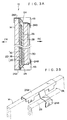
- the electrochromic anti-glare terminals 24 are each formed from a thin metal plate such as a copper plate. One end of the electrochromic anti-glare terminal 24 is bent into a substantial U-shape to form a grasping portion 24A. As illustrated in Fig.
- the grasping portion 24A nips the transparent conductive film 16 and the substrate glass 14, whereas at the bottom portion of the substrate glass 14, the grasping portion 24A nips the reflective conductive film 20 and the substrate glass 14.
- the electrochromic film 18 between the transparent conductive film 16 and the reflective conductive film 20 is energized, and the electrochromic film 18 is electrically made to color. In this way, the brightness of the reflected light reflected by the electrochromic anti-glare mirror 10 is adjusted.
- the rear surface side of the electrochromic layer 22, including leg portions 24B, is sealed with an adhesive for sealing 26. Further, a protective plate 28 made of glass, a metal, or the like is adhered to the rear surface side of the electrochromic layer 22 by the adhesive for sealing 26. The electrochromic layer 22 is protected by the protective plate 28.
- the sheet member 30 includes a plate-shaped heater 32 at a position where the sheet member 30 contacts the rear surface of the protective plate 28.
- a pair of terminals whose polarities are different from each other referred to as "heater terminals 34", hereinafter
- a heating element 35 are provided at the heater 32, and the heating element 35 extends over substantially the entire surface of the heater 32.
- the entire surface of the heater 32 is coated with a protective film which is not shown, and the heating element 35 generates heat by being energized. In this way, the heater 32 heats the substrate glass 14 and fog on the electrochromic anti-glare mirror 10 is eliminated.
- a printed circuit board 36 which is thin and flexible is provided on the rear surface of the heater 32.
- wires referred to as "wires for electrochromic anti-glare 38" hereinafter
- wires for electrochromic anti-glare 38 which are narrow, thin conductors and which are for energizing the electrochromic film 18 between the transparent conductive film 16 and reflective conductive film 20 of the electrochromic layer 22, are printed on the printed circuit board 36.
- electrochromic anti-glare electrodes 42 a pair of electrodes (referred to as “electrochromic anti-glare electrodes 42" hereinafter) is provided on the printed circuit board 36. These electrochromic anti-glare electrodes 42 are fixed to the printed circuit board 36 by rivets 42A which pass through the printed circuit board 36. This pair of electrochromic anti-glare electrodes 42 have polarities which are different from each other, and each is connected to a wire for electrochromic anti-glare 38. Electric power is supplied from the pair of electrochromic anti-glare electrodes 42 to the pair of electrochromic anti-glare terminals 24 through the wires for electrochromic anti-glare 38.
- a resistor for fail-safe 44 is printed on the printed circuit board 36.
- the resistor for fail-safe 44 is wired between the wires for electrochromic anti-glare 38.
- the resistor for fail-safe 44 discharges the electric charges generated at the electrochromic film 18 between the transparent conductive film 16 and the reflective conductive film 20, when there are problems with a power supply which will be described later and which supplies electric power to the electrochromic film 18 between the transparent conductive film 16 and the reflective conductive film 20 in the electrochromic layer 22.
- the resistor for fail-safe 44 sets the electrochromic film 18 in a state in which color cannot be generated, and acts to forcibly return the electrochromic anti-glare mirror 10 to a daytime mode.
- heater electrodes 46 are fixed to the printed circuit board 36 by rivets 46A.
- the rivets 46A are exposed at the front and rear surfaces of the printed circuit board 36. Since the heater 32 and the printed circuit board 36 are disposed in a superposed manner, the pair of heater terminals 34 of the heater 32 contact the pair of heater electrodes 46 of the printed circuit board 36, via the rivets 46A.
- the pair of heater electrodes 46 and the pair of electrochromic anti-glare electrodes 42 are disposed so as to extend longitudinally in a horizontal direction as illustrated in Fig. 4 and are disposed adjacent and parallel to each other.
- a cover sheet 48 is affixed to the rear surface of the printed circuit board 36, and the printed circuit board 36 is protected by the cover sheet 48.
- the pair of heater electrodes 46 and the pair of electrochromic anti-glare electrodes 42 are exposed from holes 48A provided at the cover sheet 48.
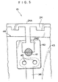
- a pair of copper alloy plates 40 are provided on the rear surface side of the cover sheet 48. As illustrated in detail in Figs. 4 and 5, the copper alloy plates 40 are fixed to the cover sheet 48 by rivets 45 which pass through the cover sheet 48.
- the portions of the rivets 45 exposed at the front surface of the cover sheet 48 are connected to final end portions (electrochromic anti-glare terminal 24 side end portions) of the wires for electrochromic anti-glare 38 of the printed circuit board 36.
- the copper alloy plates 40 are connected to the leg portions 24B of the electrochromic anti-glare terminals 24 through welded portions 41, formed by junction soldering, spot welding, ultrasonic welding, or the like.
- the pair of electrochromic anti-glare terminals 24 are connected to the wires for electrochromic anti-glare 38.
- the end portions of the wires for electrochromic anti-glare 38, the copper alloys 40, the rivets 45, and the welded portions 41 are sealed by sealing members such as silicon, butyl tape, or the like.
- a 4-pole male connector 50 is mounted to the rear surface of the cover sheet 48 and is connected to the pair of heater electrodes 46 and the pair of electrochromic anti-glare electrodes 42.
- the 4-pole male connector 50 is connected to a vehicle power supply 51B via a 4-pole female connector 51A and a cord complete (not shown). In this way, through the cord complete, the 4-pole female connector 51A, and the 4-pole male connector 50, electric power is supplied from the power supply 51B to each of the pair of heater electrodes 46 and the pair of electrochromic anti-glare electrodes 42.
- the electrochromic anti-glare mirror 10 is accommodated in a visor 52 which is a base, and the visor 52 is supported by a stay 54 at the vehicle body, e.g., at a door of the vehicle body.
- the 4-pole female connector 51A, and the 4-pole male connector 50 electric power is supplied from the power supply 51B to the heater electrodes 46 and the electrochromic anti-glare electrodes 42 provided at the printed circuit board 36.
- the wires for electrochromic anti-glare 38 are printed on the printed circuit board 36, there is no need for complex work for installing and connecting the cords as there is in conventional wiring using cords. Thus, not only can incorrect assembly be prevented, but also assemblability can be improved and the number of work processes can be reduced, and costs can thereby be reduced. Moreover, since the wires for electrochromic anti-glare 38 are printed on the printed circuit board 36, the electrochromic anti-glare mirror 10 can be made thinner and requires less space. Further, since the wires for electrochromic anti-glare 38 are printed on the printed circuit board 36 and do not move, catching of the wires for electrochromic anti-glare 38 on the other portions of the structure at the time of mirror adjustment can be suppressed.
- the resistor for fail-safe 44 printed on the printed circuit board 36 discharges electric charges of the electrochromic film 18 between the transparent conductive film 16 and the reflective conductive film 20, when there are problems with the power supply 51B which supplies electric power to the electrochromic film 18 between the transparent conductive film 16 and the reflective conductive film 20 of the electrochromic layer 22.
- the resistor for fail-safe 44 sets the electrochromic film 18 in a state in which color cannot be generated, and acts to forcibly return the electrochromic anti-glare mirror 10 to a daytime mode.
- the resistor for fail-safe 44 is printed on the printed circuit board 36, it is not necessary to wire a resistor for fail-safe within a cord complete of the wiring for electrochromic anti-glare as performed conventionally. Moreover, a process for winding a waterproof tape around the resistor for fail-safe becomes unnecessary. Thus, the number of parts and the number of work processes are decreased and costs can be reduced.
- cords which conventionally connect a heater terminal with an electrochromic anti-glare terminal are no longer needed.
- assemblability can be improved and the number of work processes can be reduced, thereby reducing costs.
- the electrochromic anti-glare mirror 10 can be made thinner and requires less space, and the catching of cords on the other portions of the structure at the time of mirror adjustment can be suppressed.
- the pair of heater electrodes 46 provided at the printed circuit board 36 are made to contact the pair of heater terminals 34 which are directly connected to the plate-shaped heater 32.
- the present invention is not limited to the same.
- a wiring which connects the pair of the heater electrodes 46 provided at the printed circuit board 36 to the pair of heater terminals 34 directly connected to the plate-shaped heater 32, may be printed on the printed circuit board 36. In this way, effects which are the same as those of the above-described embodiment can be obtained.
- a main portion of an electrochromic anti-glare mirror 60 relating to the second embodiment is illustrated in rear view.
- an electrochromic anti-glare terminal 62 is provided at each of a top portion, a bottom portion and a side portion of the substrate glass 14 and the electrochromic layer 22 (see Figs. 1-4) which have the same structures as in the previously-described embodiment.
- the electrochromic anti-glare terminal 62 at the side portion contacts the substrate glass 14 and the transparent conductive film 16, and the electrochromic anti-glare terminals 62 at the top portion and bottom portion abut the substrate glass 14 and the reflective conductive film 20. Accordingly, in the present embodiment, it is possible to electrically generate color more uniformly.
- wires for electrochromic anti-glare 66 are printed on a printed circuit board 64.
- the wires for electrochromic anti-glare 66 are connected to the three electrochromic anti-glare terminals 62 in a manner which is the same as in the first embodiment described above.
- Other structures have the same structures and effects as those of the first embodiment.
- the wires for electrochromic anti-glare 66 are printed on the printed circuit board 64.
- the wires for electrochromic anti-glare 66 are printed on the printed circuit board 64, the electrochromic anti-glare mirror 60 can be made thinner and takes up less space.
- wires for electrochromic anti-glare 66 are printed on the printed circuit board 64 and do not move, the catching of the wires for electrochromic anti-glare 66 on the other portions of the structure at the time of mirror adjustment can be suppressed.
- the resistor for fail-safe 44 is printed on the printed circuit board 64, it is not necessary to wire a resistor for fail-safe within a cord complete of the wiring for electrochromic anti-glare as performed conventionally. Moreover, a process for winding a waterproof tape around the resistor for fail-safe becomes unnecessary. Thus, the number of parts and the number of work processes are decreased and costs can be reduced.
- cords which conventionally connect a heater terminal and an electrochromic anti-glare terminal are no longer needed.
- assemblability can be improved and the number of work processes can be reduced, thereby reducing costs.
- the electrochromic anti-glare mirror 60 can be made thinner and requires less space, and catching of the cords at the time of mirror adjustment can be suppressed.
- a main portion of an electrochromic anti-glare mirror 70 which relates to the third embodiment is illustrated in rear view.
- the main portion of the electrochromic anti-glare mirror 70 is illustrated in an exploded perspective view.
- an electrochromic anti-glare terminals 72 is provided at each of the top portion, the bottom portion, and the side portion of the substrate glass 14 and the electrochromic layer 22 which have the same structures as in the previously-described embodiments.
- the electrochromic anti-glare terminal 72 at the side portion contacts the substrate glass 14 and the transparent conductive film 16, whereas the electrochromic anti-glare terminals 72 at the top portion and bottom portion contact the substrate glass 14 and the reflective conductive film 20. Accordingly, in the present third embodiment, the electrochromic film 18 can be electrically made to color more uniformly.
- wide, thin, plate-shaped conductors for electrochromic anti-glare 76 are printed on a printed circuit board 74.
- the conductors for electrochromic anti-glare 76 are connected to the three electrochromic anti-glare terminals 72 in a manner similar to that of the first embodiment described above.
- the conductors for electrochromic anti-glare 76 are connected to the pair of electrochromic anti-glare electrodes 42. Electric power is supplied to the electrochromic anti-glare terminals 72 from the pair of electrochromic anti-glare electrodes 42 via the conductors for electrochromic anti-glare 76.
- the pair of electrochromic anti-glare electrodes 42 are disposed separately at the upper portion and the lower portion of the printed circuit board 74.
- the resistor for fail-safe 44 is wired between the conductors for electrochromic anti-glare 76.
- the pair of heater electrodes 46 which supply electric power the pair of heater terminals 34 are disposed separately at the upper portion and the lower portion of the printed circuit board 74. Accordingly, one of the heater electrodes 46 and one of the electrochromic anti-glare electrodes 42 form a set, and one of these sets of a heater electrode 46 and an electrochromic anti-glare electrode 42 is provided at each of the upper portion and the lower portion of the printed circuit board 74. Further, in the same way as in Fig. 4, the heater electrodes 46 and the electrochromic anti-glare electrodes 42 are exposed from the holes 48A in the cover sheet 48.
- a pair of 2-pole male connectors 78 that have polarities different from each other are mounted on the rear surface of the cover sheet 48.
- the 2-pole male connectors 78 are connected to the respective sets of the heater electrode 46 and the electrochromic anti-glare electrode 42 which are disposed at the upper portion and the lower portion of the printed circuit board 74.
- the 2-pole male connectors 78 are connected to a cord complete (not shown) through 2-pole female connectors (also not shown).
- the cord complete is connected to a power supply (not shown). In this way, electric power is supplied from the power source to the pair of heater electrodes 46 and the pair of electrochromic anti-glare electrodes 42 through the cord complete, the 2-pole female connectors, and the 2-pole male connectors 78.
- the conductors for electrochromic anti-glare 76 are printed on the printed circuit board 74, there is no need for complicated work for installing and connecting cords as there is in the conventional structure in which the wires are cords. Therefore, not only can incorrect assembly be prevented, but also, assemblability can be improved and the number of work processes can be reduced, thereby reducing costs. Further, since the conductors for electrochromic anti-glare 76 are printed on the printed circuit board 74, the electrochromic anti-glare mirror 70 can be made thinner and requires less space.
- the resistor for fail-safe 44 is printed on the printed circuit board 74, it is not necessary to wire a resistor for fail-safe within a cord complete of the wiring for electrochromic anti-glare as performed conventionally. Moreover, a process for winding a waterproof tape around the resistor for fail-safe becomes unnecessary. Thus, the number of parts and the number of work processes are decreased and costs can be reduced.
- cords which conventionally connect a heater terminal and an electrochromic anti-glare terminal are no longer needed.
- assemblability can be improved and the number of work processes can be reduced, thereby reducing costs.
- the electrochromic anti-glare mirror 70 can be made thinner and requires less space, and catching of the cords at the time of mirror adjustment can be suppressed.
Landscapes
- Engineering & Computer Science (AREA)
- Chemical & Material Sciences (AREA)
- Crystallography & Structural Chemistry (AREA)
- Multimedia (AREA)
- Mechanical Engineering (AREA)
- Electrochromic Elements, Electrophoresis, Or Variable Reflection Or Absorption Elements (AREA)
- Rear-View Mirror Devices That Are Mounted On The Exterior Of The Vehicle (AREA)
- Optical Elements Other Than Lenses (AREA)
Description
- The present invention relates to an electrochromic anti-glare mirror for electrically iron reflectance when connected to a power supply with the features of first part of claim 1 as known from
US 5820245 A . - Among vehicle mirrors to be installed on a vehicle, there are so-called electrochromic anti-glare mirrors in which an electrochromic film provided on a rear surface side of a substrate glass is made to color electrically such that the brightness of reflected light can be adjusted. In this electrochromic anti-glare mirror, for example, a transparent conductive film is provided on the rear surface of the substrate glass, and, on the rear surface of the transparent conductive film, an electrochromic film is provided. On the rear surface of the electrochromic film, a reflective conductive film made of aluminum or the like is provided. An electrochromic layer is formed by the transparent conductive film, electrochromic film, and the reflective conductive film. A protective plate made of glass, a metal, or the like is adhered by an adhesive for sealing to the rear surface of this electrochromic layer, and the electrochromic layer is protected by this protective plate.
- The electrochromic anti-glare mirror has a pair of electrochromic anti-glare terminals. One of the electrochromic anti-glare terminals contacts the substrate glass and the transparent conductive film, whereas the other electrochromic anti-glare terminal contacts the substrate glass and the reflective conductive film. The wires, to this pair of the electrochromic anti-glare terminals, for energizing the electrochromic film between the transparent conductive film and the reflective conductive film are cords (These wires will be referred to hereinafter as "the wires for electrochromic anti-glare"). A pair of electrodes (referred to hereinafter as "electrochromic anti-glare electrodes") are connected to these wires for electrochromic anti-glare. By supplying electric power to the electrochromic film between the transparent conductive film and the reflective conductive film from these electrochromic anti-glare electrodes through the wires for electrochromic anti-glare, the electrochromic film between the transparent conductive film and the reflective conductive film is energized, and the electrochromic film is electrically made to color. In this way, the brightness of the light reflected by the electrochromic anti-glare mirror is adjusted.
- Further, a fail-safe resistor is connected within the cord complete of the wires for electrochromic anti-glare. When there are problems with the power supply which supplies electric power to the electrochromic film between the transparent conductive film and the reflective conductive film, the fail-safe resistor discharges the electric charges of the electrochromic film between the transparent conductive film and the reflective conductive film. In this way, the fail-safe resistor does not allow the electrochromic film to color, and acts to forcibly return the electrochromic anti-glare mirror to a mode for day time.
- Further, a heater is provided on the rear surface of the protective plate. A pair of heater terminals are provided at the heater, and the heater generates heat by being energized. The wires to the heater terminals (hereinafter referred to as the "wires for the heater") for energizing the heater are cords. A pair of electrodes (referred to as "the heater electrodes", hereinafter) are connected to the wires for the heater. By supplying electric power from this pair of heater electrodes to the heater through the wires, the heater is energized and generates heat. In this way, the heater heats the substrate glass and fog on the electrochromic anti-glare mirror is eliminated.
- However, with such an electrochromic anti-glare mirror, because cords are used for the wires for electrochromic anti-glare and the wires for the heater, work involved in installing and connecting the cords is complex. As a result, it is easy for incorrect assembly to occur, assemblability is poor, and assembly involves many work steps. Therefore, the cost becomes high. Further, since these cords are attached by a butyl tape or the like to the rear surface of the heater, the electrochromic anti-glare mirror becomes thick and the space for accommodating the electrochromic anti-glare mirror becomes large. Moreover, since the cords move at the time of mirror adjustment, the cords are easily caught on other portions of the structure.
- Further, since the resistor for fail-safe is wires within the cord complete of the wires for electrochromic anti-glare and a process of winding waterproof tape around this resistor for fail-safe is needed, the number of components and work processes increase, and as a result, the cost becomes high.
-
US 5820245 A andUS 5659423 A disclose an electrochromic anti-glare mirror with the features of first part of claim 1.US 5504478 A discloses an electrochromic anti-glare mirror wherein the circuit board includes two types of conductors having polarities different from each other for supplying electric power to the electrochromic layer. - In view of the aforementioned, an object of the present invention is to obtain an electrochromic anti-glare mirror in which, by using a circuit board as the wiring for making an electrochromic film generate color electrically, incorrect assembly can be prevented and assemblability is improved, and, therefore, the number of the work processes decreases and the cost can be reduced.
- An electrochromic anti-glare mirror according to the present invention includes the features of claim 1. The subject matter of sub-claims are preferred embodiments.
- In accordance with the electrochromic anti-glare mirror of the present invention, a conductor for energizing an electrochromic film is provided on a circuit board, and electric power is supplied to the electrochromic film through the conductor. The electrochromic film is thereby energized and made to color electrically. In this way, brightness of light reflected by the electrochromic anti-glare mirror is adjusted.
- Here, since the conductor is provided at the circuit board, there is no need for complicated work for installing and connecting cords as there is in the conventional structure in which the wires are cords. Therefore, not only can incorrect assembly be prevented, but also, assemblability can be improved and the number of work processes can be reduced, thereby reducing costs. Further, since the conductor can be made thin, the electrochromic anti-glare mirror can be made thinner and requires less space. Moreover, since the conductor is fixed to the circuit board by printing or the like, catching of the wire for electrochromic anti-glare on the other portions of the structure at the time of mirror adjustment can be suppressed.
- It should be noted that, although a transparent substrate is provided in front of the electrochromic layer, the material of this transparent substrate is not limited to glass, and plastic may be used for example. Moreover, the technique for providing the conductor on the circuit board may be any technique such as printing, etching, adhesion, or the like. Further, the reflective film may be provided separately from the electrochromic layer.
-
- Fig. 1 is a rear view illustrating a main portion of an electrochromic anti-glare mirror which relates to an embodiment of the present invention.
- Fig. 2 is a front view illustrating the exterior of the electrochromic anti-glare mirror.
- Fig. 3A is a cross-sectional view illustrating a schematic structure of the electrochromic anti-glare mirror taken along line 3-3 in Fig. 1.
- Fig. 3B is a perspective view illustrating electrochromic anti-glare terminals.
- Fig. 4 is an exploded perspective view illustrating a main portion of the electrochromic anti-glare mirror.
- Fig. 5 is a rear view illustrating connecting portion which connects an electrochromic anti-glare terminal of the electrochromic anti-glare mirror and a wire for electrochromic anti-glare.
- Fig. 6 is a rear view illustrating a main portion of an electrochromic anti-glare mirror which relates to a second embodiment of the present invention.
- Fig. 7 is a rear view illustrating a main portion of an electrochromic anti-glare mirror which relates to a third embodiment of the present invention.
- Fig. 8 is an exploded perspective view illustrating a main portion of the electrochromic anti-glare mirror which relates to the third embodiment of the present invention.
- In Fig. 1, a main portion of an electrochromic
anti-glare mirror 10 which relates to an embodiment of the present invention is illustrated in rear view, and in Fig. 2, the exterior of the electrochromicanti-glare mirror 10 is illustrated in front view. Moreover, in Fig. 3, the schematic structure of the electrochromicanti-glare mirror 10 is illustrated in a cross-sectional view, and in Fig. 4, a structure of the main portion of the electrochromicanti-glare mirror 10 is illustrated in an exploded perspective view. Arrows FR in the drawings indicate "front" of the mirror and arrows RE indicate "rear" of the mirror (rear surface). External light enters into the electrochromicanti-glare mirror 10 in a direction opposite to the direction of arrow FR and is reflected in the direction of arrow FR. - As illustrated in Fig. 3, the electrochromic
anti-glare mirror 10 has asubstrate glass 14. On the rear surface (RE direction surface) of thesubstrate glass 14, a transparentconductive film 16 is provided, and on the rear surface of the transparentconductive film 16, an electrochromic film 18 is provided. Moreover, on the rear surface of the electrochromic film 18, a reflectiveconductive film 20 formed of aluminum or the like is provided. An electrochromic layer 22 is formed by the transparentconductive film 16, the electrochromic film 18, and the reflectiveconductive film 20. Here, at the top portion and the bottom portion of thesubstrate glass 14 and the electrochromic layer 22, a pair of terminals (referred to as "electrochromicanti-glare terminals 24", hereinafter) are provided. The electrochromicanti-glare terminal 24 at the top side contacts thesubstrate glass 14 and the transparentconductive film 16, and the electrochromicanti-glare terminal 24 at the bottom side contacts thesubstrate glass 14 and the reflectiveconductive film 20. As illustrated in Fig. 3B, the electrochromicanti-glare terminals 24 are each formed from a thin metal plate such as a copper plate. One end of the electrochromicanti-glare terminal 24 is bent into a substantial U-shape to form a graspingportion 24A. As illustrated in Fig. 3A, at the upper portion of thesubstrate glass 14, the graspingportion 24A nips the transparentconductive film 16 and thesubstrate glass 14, whereas at the bottom portion of thesubstrate glass 14, the graspingportion 24A nips the reflectiveconductive film 20 and thesubstrate glass 14. By supplying electric power to the electrochromic film 18 between the transparentconductive film 16 and the reflectiveconductive film 20 through this pair of electrochromicanti-glare terminals 24, the electrochromic film 18 between the transparentconductive film 16 and the reflectiveconductive film 20 is energized, and the electrochromic film 18 is electrically made to color. In this way, the brightness of the reflected light reflected by the electrochromicanti-glare mirror 10 is adjusted. - The rear surface side of the electrochromic layer 22, including
leg portions 24B, is sealed with an adhesive for sealing 26. Further, aprotective plate 28 made of glass, a metal, or the like is adhered to the rear surface side of the electrochromic layer 22 by the adhesive for sealing 26. The electrochromic layer 22 is protected by theprotective plate 28. - On the rear surface of the
protective plate 28, asheet member 30 is provided. Thesheet member 30 includes a plate-shapedheater 32 at a position where thesheet member 30 contacts the rear surface of theprotective plate 28. As illustrated in Fig. 4, a pair of terminals whose polarities are different from each other (referred to as "heater terminals 34", hereinafter) and aheating element 35 are provided at theheater 32, and theheating element 35 extends over substantially the entire surface of theheater 32. The entire surface of theheater 32 is coated with a protective film which is not shown, and theheating element 35 generates heat by being energized. In this way, theheater 32 heats thesubstrate glass 14 and fog on the electrochromicanti-glare mirror 10 is eliminated. - On the rear surface of the
heater 32, a printedcircuit board 36 which is thin and flexible is provided. As illustrated in Fig. 1 and Fig. 4, on the printedcircuit board 36, wires (referred to as "wires for electrochromic anti-glare 38" hereinafter), which are narrow, thin conductors and which are for energizing the electrochromic film 18 between the transparentconductive film 16 and reflectiveconductive film 20 of the electrochromic layer 22, are printed on the printedcircuit board 36. - Further, a pair of electrodes (referred to as "electrochromic
anti-glare electrodes 42" hereinafter) is provided on the printedcircuit board 36. These electrochromicanti-glare electrodes 42 are fixed to the printedcircuit board 36 byrivets 42A which pass through the printedcircuit board 36. This pair of electrochromicanti-glare electrodes 42 have polarities which are different from each other, and each is connected to a wire forelectrochromic anti-glare 38. Electric power is supplied from the pair of electrochromicanti-glare electrodes 42 to the pair of electrochromicanti-glare terminals 24 through the wires forelectrochromic anti-glare 38. - Further, a resistor for fail-safe 44 is printed on the printed
circuit board 36. The resistor for fail-safe 44 is wired between the wires forelectrochromic anti-glare 38. The resistor for fail-safe 44 discharges the electric charges generated at the electrochromic film 18 between the transparentconductive film 16 and the reflectiveconductive film 20, when there are problems with a power supply which will be described later and which supplies electric power to the electrochromic film 18 between the transparentconductive film 16 and the reflectiveconductive film 20 in the electrochromic layer 22. In this way, the resistor for fail-safe 44 sets the electrochromic film 18 in a state in which color cannot be generated, and acts to forcibly return the electrochromicanti-glare mirror 10 to a daytime mode. - In the same way as the electrochromic
anti-glare electrodes 42,heater electrodes 46 are fixed to the printedcircuit board 36 byrivets 46A. Therivets 46A are exposed at the front and rear surfaces of the printedcircuit board 36. Since theheater 32 and the printedcircuit board 36 are disposed in a superposed manner, the pair ofheater terminals 34 of theheater 32 contact the pair ofheater electrodes 46 of the printedcircuit board 36, via therivets 46A. The pair ofheater electrodes 46 and the pair of electrochromicanti-glare electrodes 42 are disposed so as to extend longitudinally in a horizontal direction as illustrated in Fig. 4 and are disposed adjacent and parallel to each other. - As illustrated in Fig. 4, a
cover sheet 48 is affixed to the rear surface of the printedcircuit board 36, and the printedcircuit board 36 is protected by thecover sheet 48. The pair ofheater electrodes 46 and the pair of electrochromicanti-glare electrodes 42 are exposed fromholes 48A provided at thecover sheet 48. Further, a pair ofcopper alloy plates 40 are provided on the rear surface side of thecover sheet 48. As illustrated in detail in Figs. 4 and 5, thecopper alloy plates 40 are fixed to thecover sheet 48 byrivets 45 which pass through thecover sheet 48. Accordingly, the portions of therivets 45 exposed at the front surface of thecover sheet 48 are connected to final end portions (electrochromicanti-glare terminal 24 side end portions) of the wires forelectrochromic anti-glare 38 of the printedcircuit board 36. Further, thecopper alloy plates 40 are connected to theleg portions 24B of the electrochromicanti-glare terminals 24 through weldedportions 41, formed by junction soldering, spot welding, ultrasonic welding, or the like. In this way, the pair of electrochromicanti-glare terminals 24 are connected to the wires forelectrochromic anti-glare 38. Further, the end portions of the wires for electrochromic anti-glare 38, thecopper alloys 40, therivets 45, and the weldedportions 41 are sealed by sealing members such as silicon, butyl tape, or the like. - A 4-
pole male connector 50 is mounted to the rear surface of thecover sheet 48 and is connected to the pair ofheater electrodes 46 and the pair of electrochromicanti-glare electrodes 42. The 4-pole male connector 50 is connected to avehicle power supply 51B via a 4-polefemale connector 51A and a cord complete (not shown). In this way, through the cord complete, the 4-polefemale connector 51A, and the 4-pole male connector 50, electric power is supplied from thepower supply 51B to each of the pair ofheater electrodes 46 and the pair of electrochromicanti-glare electrodes 42. - As illustrated in Fig. 2, the electrochromic
anti-glare mirror 10 is accommodated in avisor 52 which is a base, and thevisor 52 is supported by astay 54 at the vehicle body, e.g., at a door of the vehicle body. - Next, operation of the present embodiment will be described.
- In the electrochromic
anti-glare mirror 10 having the above-described structure, through the cord complete, the 4-polefemale connector 51A, and the 4-pole male connector 50, electric power is supplied from thepower supply 51B to theheater electrodes 46 and the electrochromicanti-glare electrodes 42 provided at the printedcircuit board 36. - When electric power is supplied to the pair of electrochromic
anti-glare electrodes 42, electric power is supplied to the pair of electrochromicanti-glare terminals 24 through the wires for electrochromic anti-glare 38 printed on the printedcircuit board 36. As a result, electric power is supplied through the pair of electrochromicanti-glare terminals 24 to the electrochromic film 18 between the transparentconductive film 16 and the reflectiveconductive film 20 in the electrochromic layer 22, and the electrochromic film 18 between the transparentconductive film 16 and the reflectiveconductive film 20 is energized, and is electrically made to color. In this way, the brightness of the reflected light reflected by the electrochromicanti-glare mirror 10 is adjusted. - Here, since the wires for electrochromic anti-glare 38 are printed on the printed
circuit board 36, there is no need for complex work for installing and connecting the cords as there is in conventional wiring using cords. Thus, not only can incorrect assembly be prevented, but also assemblability can be improved and the number of work processes can be reduced, and costs can thereby be reduced. Moreover, since the wires for electrochromic anti-glare 38 are printed on the printedcircuit board 36, the electrochromicanti-glare mirror 10 can be made thinner and requires less space. Further, since the wires for electrochromic anti-glare 38 are printed on the printedcircuit board 36 and do not move, catching of the wires for electrochromic anti-glare 38 on the other portions of the structure at the time of mirror adjustment can be suppressed. - Further, the resistor for fail-safe 44 printed on the printed
circuit board 36 discharges electric charges of the electrochromic film 18 between the transparentconductive film 16 and the reflectiveconductive film 20, when there are problems with thepower supply 51B which supplies electric power to the electrochromic film 18 between the transparentconductive film 16 and the reflectiveconductive film 20 of the electrochromic layer 22. In this way, the resistor for fail-safe 44 sets the electrochromic film 18 in a state in which color cannot be generated, and acts to forcibly return the electrochromicanti-glare mirror 10 to a daytime mode. - Here, since the resistor for fail-safe 44 is printed on the printed
circuit board 36, it is not necessary to wire a resistor for fail-safe within a cord complete of the wiring for electrochromic anti-glare as performed conventionally. Moreover, a process for winding a waterproof tape around the resistor for fail-safe becomes unnecessary. Thus, the number of parts and the number of work processes are decreased and costs can be reduced. - On the other hand, when electric power is supplied to the pair of
heater electrodes 46, electric power is supplied from the pair ofheater electrodes 46 to the pair ofheater terminals 34. In this way, theheater 32 is energized and generates heat. Theheater 32 thereby heats thesubstrate glass 14 so that fog on the electrochromicanti-glare mirror 10 is eliminated. - Here, cords which conventionally connect a heater terminal with an electrochromic anti-glare terminal are no longer needed. As a result, there is no need for complex work for installing and connecting the cords as there is conventionally. Not only can incorrect assembly be prevented, but also, assemblability can be improved and the number of work processes can be reduced, thereby reducing costs. Accordingly, the electrochromic
anti-glare mirror 10 can be made thinner and requires less space, and the catching of cords on the other portions of the structure at the time of mirror adjustment can be suppressed. - Further, in the present embodiment, the pair of
heater electrodes 46 provided at the printedcircuit board 36 are made to contact the pair ofheater terminals 34 which are directly connected to the plate-shapedheater 32. The present invention is not limited to the same. A wiring which connects the pair of theheater electrodes 46 provided at the printedcircuit board 36 to the pair ofheater terminals 34 directly connected to the plate-shapedheater 32, may be printed on the printedcircuit board 36. In this way, effects which are the same as those of the above-described embodiment can be obtained. - In Fig. 6, a main portion of an electrochromic
anti-glare mirror 60 relating to the second embodiment is illustrated in rear view. - As illustrated in Fig. 6, in the electrochromic
anti-glare mirror 60 relating to the present second embodiment, an electrochromicanti-glare terminal 62 is provided at each of a top portion, a bottom portion and a side portion of thesubstrate glass 14 and the electrochromic layer 22 (see Figs. 1-4) which have the same structures as in the previously-described embodiment. The electrochromicanti-glare terminal 62 at the side portion contacts thesubstrate glass 14 and the transparentconductive film 16, and the electrochromicanti-glare terminals 62 at the top portion and bottom portion abut thesubstrate glass 14 and the reflectiveconductive film 20. Accordingly, in the present embodiment, it is possible to electrically generate color more uniformly. Further, wires for electrochromic anti-glare 66 are printed on a printedcircuit board 64. The wires for electrochromic anti-glare 66 are connected to the three electrochromicanti-glare terminals 62 in a manner which is the same as in the first embodiment described above. Other structures have the same structures and effects as those of the first embodiment. - Here, even in a case in which three
electrochromic terminals 62 are provided as in the present second embodiment, the wires for electrochromic anti-glare 66 are printed on the printedcircuit board 64. As a result, there is no need for a complex operation for installing and connecting cords as there is in the conventional structure in which the wires are cords. Therefore, not only can incorrect assembly be prevented, but also, assemblability can be improved and the number of work processes can be reduced, thereby reducing costs. Further, since the wires for electrochromic anti-glare 66 are printed on the printedcircuit board 64, the electrochromicanti-glare mirror 60 can be made thinner and takes up less space. Further, since the wires for electrochromic anti-glare 66 are printed on the printedcircuit board 64 and do not move, the catching of the wires for electrochromic anti-glare 66 on the other portions of the structure at the time of mirror adjustment can be suppressed. - Further, since the resistor for fail-safe 44 is printed on the printed
circuit board 64, it is not necessary to wire a resistor for fail-safe within a cord complete of the wiring for electrochromic anti-glare as performed conventionally. Moreover, a process for winding a waterproof tape around the resistor for fail-safe becomes unnecessary. Thus, the number of parts and the number of work processes are decreased and costs can be reduced. - Moreover, cords which conventionally connect a heater terminal and an electrochromic anti-glare terminal are no longer needed. As a result, there is no need for complicated work for installing and connecting the cords as there is conventionally. Not only can incorrect assembly be prevented, but also, assemblability can be improved and the number of work processes can be reduced, thereby reducing costs. Further, accordingly, the electrochromic
anti-glare mirror 60 can be made thinner and requires less space, and catching of the cords at the time of mirror adjustment can be suppressed. - In Fig. 7, a main portion of an electrochromic
anti-glare mirror 70 which relates to the third embodiment is illustrated in rear view. In Fig. 8, the main portion of the electrochromicanti-glare mirror 70 is illustrated in an exploded perspective view. - In the electrochromic
anti-glare mirror 70 relating to the present embodiment, an electrochromicanti-glare terminals 72 is provided at each of the top portion, the bottom portion, and the side portion of thesubstrate glass 14 and the electrochromic layer 22 which have the same structures as in the previously-described embodiments. The electrochromicanti-glare terminal 72 at the side portion contacts thesubstrate glass 14 and the transparentconductive film 16, whereas the electrochromicanti-glare terminals 72 at the top portion and bottom portion contact thesubstrate glass 14 and the reflectiveconductive film 20. Accordingly, in the present third embodiment, the electrochromic film 18 can be electrically made to color more uniformly. - Moreover, wide, thin, plate-shaped conductors for electrochromic anti-glare 76 are printed on a printed
circuit board 74. The conductors for electrochromic anti-glare 76 are connected to the three electrochromicanti-glare terminals 72 in a manner similar to that of the first embodiment described above. The conductors for electrochromic anti-glare 76 are connected to the pair of electrochromicanti-glare electrodes 42. Electric power is supplied to the electrochromicanti-glare terminals 72 from the pair of electrochromicanti-glare electrodes 42 via the conductors forelectrochromic anti-glare 76. Further, the pair of electrochromicanti-glare electrodes 42 are disposed separately at the upper portion and the lower portion of the printedcircuit board 74. Moreover, the resistor for fail-safe 44 is wired between the conductors forelectrochromic anti-glare 76. - The pair of
heater electrodes 46 which supply electric power the pair ofheater terminals 34 are disposed separately at the upper portion and the lower portion of the printedcircuit board 74. Accordingly, one of theheater electrodes 46 and one of the electrochromicanti-glare electrodes 42 form a set, and one of these sets of aheater electrode 46 and an electrochromicanti-glare electrode 42 is provided at each of the upper portion and the lower portion of the printedcircuit board 74. Further, in the same way as in Fig. 4, theheater electrodes 46 and the electrochromicanti-glare electrodes 42 are exposed from theholes 48A in thecover sheet 48. - A pair of 2-
pole male connectors 78 that have polarities different from each other are mounted on the rear surface of thecover sheet 48. The 2-pole male connectors 78 are connected to the respective sets of theheater electrode 46 and the electrochromicanti-glare electrode 42 which are disposed at the upper portion and the lower portion of the printedcircuit board 74. The 2-pole male connectors 78 are connected to a cord complete (not shown) through 2-pole female connectors (also not shown). The cord complete is connected to a power supply (not shown). In this way, electric power is supplied from the power source to the pair ofheater electrodes 46 and the pair of electrochromicanti-glare electrodes 42 through the cord complete, the 2-pole female connectors, and the 2-pole male connectors 78. - Here, even in a case in which three electrochromic
anti-glare terminals 72 are provided as described in the present third embodiment, since the conductors for electrochromic anti-glare 76 are printed on the printedcircuit board 74, there is no need for complicated work for installing and connecting cords as there is in the conventional structure in which the wires are cords. Therefore, not only can incorrect assembly be prevented, but also, assemblability can be improved and the number of work processes can be reduced, thereby reducing costs. Further, since the conductors for electrochromic anti-glare 76 are printed on the printedcircuit board 74, the electrochromicanti-glare mirror 70 can be made thinner and requires less space. Moreover, since the conductors for electrochromic anti-glare 76 are printed on the printedcircuit board 74 and do not moves, catching of the conductors for electrochromic anti-glare 76 on the other portions of the structure at the time of mirror adjustment can be suppressed. - Further, since the resistor for fail-safe 44 is printed on the printed
circuit board 74, it is not necessary to wire a resistor for fail-safe within a cord complete of the wiring for electrochromic anti-glare as performed conventionally. Moreover, a process for winding a waterproof tape around the resistor for fail-safe becomes unnecessary. Thus, the number of parts and the number of work processes are decreased and costs can be reduced. - Moreover, cords which conventionally connect a heater terminal and an electrochromic anti-glare terminal are no longer needed. As a result, there is no need for complicated work for installing and connecting the cords as there is conventionally. Not only can incorrect assembly be prevented, but also, assemblability can be improved and the number of work processes can be reduced, thereby reducing costs. Further, accordingly, the electrochromic
anti-glare mirror 70 can be made thinner and requires less space, and catching of the cords at the time of mirror adjustment can be suppressed.
Claims (11)
- An electrochromic anti-glare mirror (10, 60, 70) for electrically altering reflectance when connected to a power supply (5 1 B), said mirror (10, 60) comprising:(a) a transparent glass layer (14)(b) an electrochromic layer (22), having an transparent conductive film (16) disposed at the rear side of said glass layer (14), an electrochromic film (18) disposed at the rear side of said transparent conductive film (16) and a reflective conductive film (20) disposed at the rear side of said electrochromic film,(c) a first electrochromic anti-glare terminal (24) having a grasping portion (24A) nipping the transparent glass layer (14) and the transparent conductive film (16) and a second anti-glare terminal (24) having a grasping portion (24A) nipping the transparent glass layer (14) and the reflective conductive film (20),(d) a circuit board (36, 64, 74) disposed at the rear side of the reflective conductive film (20), said circuit board (36, 64, 74) having a conductor (38, 66, 76) with two ends, one end being for connection to the electrochromic layer (22) and the other end being for connection to a power supply (5 1 B),(e) a cover member (48) disposed at the rear side of the circuit board (36, 64, 74), said cover member (48) comprising a connector (50) for connecting the circuit board (36, 64, 74) to the power supply (51 B),characterized in that
a pair of conductive plates (40) is affixed to the rear side of the cover member (48) by conductive fixation means (45), said fixation means (45) extending through the cover member (48) to the front side of the cover member (48) and connected to the one end of the conductor (38, 66, 76) on the circuit board (36, 64, 74), and
the first and the second anti-glare terminals (24) comprise a leg portion (24B), each connected to one of the pair of conductive plates (40) on the rear side of the cover member (48), thereby nipping the transparent glass layer (14) and the cover member (48). - The electrochromic anti-glare mirror (10, 60, 70) according to claim 1, characterized in that the leg portion (24B) is welded to the conductive plate (40).
- The electrochromic anti-glare mirror (10, 60, 70) according to one of the claims 1 or 2, characterized in that a heater (32) is provided between the reflective conductive film (20) and the circuit board (36, 64, 74), and the circuit board (36, 64, 74) includes a conductor (38, 66, 76) for supplying electric power to the heater.
- The electrochromic anti-glare mirror (10, 60, 70) according to one of the claims 1, 2 or 3, characterized in that the rear side of the electrochromic layer (22) is sealed with an adhesive (26).
- The electrochromic anti-glare mirror (10, 60, 70) according to claim 4, characterized in that a protective plate (28) is adhered to the rear side of the electrochromic layer (22) by the adhesive (26).
- The electrochromic anti-glare mirror (10, 60, 70) according to claim 5, characterized in that the protective plate (28) is made of glass or metal.
- The electrochromic anti-glare mirror (10, 60, 70) according to one of the claims 3 to 6, comprising a heater (32) having ends, wherein the power supply (51B) and circuit board (36, 64, 74) are connected via two types of wires (38, 66, 76) whose polarities are different from each other, the circuit board (36, 64, 74) including:(a) first electrode terminals (46) connected to one of the two types of wires (38, 66, 76), the first electrode terminals (46) consisting of an electrode terminal connected to a portion of the electrochromic layer (22) and an electrode terminal connected to one end of the heater (32); and(b) second electrode terminals (42) connected to the other of two types of wires (38, 66, 76), the second electrode terminal (42) consisting of an electrode terminal connected to another portion of the electrochromic layer (22) and an electrode terminal connected to another end of the heater (32).
- The electrochromic anti-glare mirror (10, 60, 70) according to one of the claims 1 to 7, wherein the circuit board (36, 64, 74) includes two types of conductors (24) having polarities different from each other for supplying electric power to the electrochromic layer (22) and the electrochromic layer (22) is formed in a laminated configuration (24) and includes opposite edges, with one of the two types of conductors (24) connected to one edge, and the other type of the two types of conductors (24) connected to the opposite edge.
- The electrochromic anti-glare mirror (10, 60, 70) according to one of the claims 1 to 7, wherein the circuit board (36, 64, 74) includes two types of conductors (24) having polarities different from each other for supplying electric power to the electrochromic layer (22), and the electrochromic layer (22) is formed in laminated configuration and includes a periphery, with one of the two types of conductors (24) connected to a set of plural locations spaced apart from one another along the periphery, and the other type of the two types of conductors (24) connects to a location different from said set of the plural locations along the periphery.
- The electrochromic anti-glare mirror (10, 60, 70) according to one of the claims 3 to 9, characterized in that the transparent glass layer (14), the electrochromic layer (22), the protective plate (28), the heater (32), the circuit board (36, 64, 74), and the cover member (48) are all approximately parallel to one another.
- The electrochromic anti-glare mirror (10, 60, 70) according to one of the previous claims, characterized in that a resistor fail-safe (44) is printed on the circuit board (36, 64, 74).
Applications Claiming Priority (2)
| Application Number | Priority Date | Filing Date | Title |
|---|---|---|---|
| JP15393899 | 1999-06-01 | ||
| JP15393899 | 1999-06-01 |
Publications (3)
| Publication Number | Publication Date |
|---|---|
| EP1057693A2 EP1057693A2 (en) | 2000-12-06 |
| EP1057693A3 EP1057693A3 (en) | 2003-04-02 |
| EP1057693B1 true EP1057693B1 (en) | 2007-06-27 |
Family
ID=15573371
Family Applications (1)
| Application Number | Title | Priority Date | Filing Date |
|---|---|---|---|
| EP00111410A Expired - Lifetime EP1057693B1 (en) | 1999-06-01 | 2000-05-26 | Electrochromic anti-glare mirror |
Country Status (3)
| Country | Link |
|---|---|
| US (1) | US6583919B1 (en) |
| EP (1) | EP1057693B1 (en) |
| DE (1) | DE60035312T2 (en) |
Families Citing this family (18)
| Publication number | Priority date | Publication date | Assignee | Title |
|---|---|---|---|---|
| US7522911B2 (en) * | 2000-04-11 | 2009-04-21 | Telecommunication Systems, Inc. | Wireless chat automatic status tracking |
| US6561460B2 (en) * | 2000-08-03 | 2003-05-13 | Ppg Industries Ohio, Inc. | Switchable electrochromic devices for use in aircraft transparency windows |
| EP1413137A4 (en) * | 2001-07-31 | 2005-03-02 | Illinois Tool Works | Power distribution system |
| WO2003091072A1 (en) * | 2002-04-23 | 2003-11-06 | Magna Donnelly Mirrors North America, L.L.C. | Vehicle mirror having polymeric reflective film element and self-dimming element |
| US20040145902A1 (en) * | 2003-01-28 | 2004-07-29 | Todd Daniel R. | Heated mirror assembly |
| US7241037B2 (en) * | 2005-03-23 | 2007-07-10 | K.W. Muth Company | Signaling assembly |
| US9782949B2 (en) | 2008-05-30 | 2017-10-10 | Corning Incorporated | Glass laminated articles and layered articles |
| US8432600B2 (en) * | 2009-07-30 | 2013-04-30 | Control Solutions LLC | Light blocking apparatus for vehicle mirror assembly |
| US8200390B2 (en) * | 2009-07-30 | 2012-06-12 | Control Solutions LLC | Securable cover for vehicle lights |
| US8248680B2 (en) * | 2009-07-31 | 2012-08-21 | Control Solutions LLC | Electrically activatable light blocking cover for vehicle mirrors |
| US8256940B2 (en) * | 2009-09-16 | 2012-09-04 | Control Solutions LLC | Securable cover with electrically activatable light inhibiting lens for vehicle lights |
| US20110199328A1 (en) * | 2010-02-18 | 2011-08-18 | Flextronics Ap, Llc | Touch screen system with acoustic and capacitive sensing |
| GB201019212D0 (en) | 2010-11-12 | 2010-12-29 | Dupont Teijin Films Us Ltd | Polyester film |
| CN102862520A (en) * | 2012-09-25 | 2013-01-09 | 江苏亿成光电科技有限公司 | Automatic anti-dazzling rear-view mirror |
| DE102015216925B4 (en) * | 2015-09-03 | 2019-07-04 | Magna Mirrors Holding Gmbh | Arrangement with a liquid crystal arrangement with electrically controllable light transmission and rearview mirror with an electrically dimming rearview mirror glass |
| CN112255799B (en) * | 2020-11-09 | 2023-03-21 | Oppo广东移动通信有限公司 | Wearable device and control method of wearable device |
| CN115016188A (en) * | 2022-06-30 | 2022-09-06 | 武汉华星光电半导体显示技术有限公司 | Display device and vehicle |
| WO2025191448A1 (en) * | 2024-03-11 | 2025-09-18 | Gentex Corporation | Rearview mirror heater assembly |
Family Cites Families (11)
| Publication number | Priority date | Publication date | Assignee | Title |
|---|---|---|---|---|
| DE3379078D1 (en) | 1982-10-20 | 1989-03-02 | Secr Defence Brit | Liquid crystal mirror displays |
| US5910854A (en) * | 1993-02-26 | 1999-06-08 | Donnelly Corporation | Electrochromic polymeric solid films, manufacturing electrochromic devices using such solid films, and processes for making such solid films and devices |
| US5504478A (en) | 1994-01-12 | 1996-04-02 | Gentex Corporation | Radio frequency control system |
| US5659423A (en) * | 1994-09-30 | 1997-08-19 | Donnelly Corporation | Modular variable reflectance mirror assembly |
| US5820245A (en) | 1995-12-11 | 1998-10-13 | Donnelly Corporation | Rearview mirror assembly |
| US6000823A (en) * | 1995-12-11 | 1999-12-14 | Donnelly Mirrors Limited | Rearview mirror assembly |
| US6166848A (en) * | 1997-04-02 | 2000-12-26 | Gentex Corporation | Electrochromic rearview mirror incorporating a third surface metal reflector and a display/signal light |
| US6124886A (en) * | 1997-08-25 | 2000-09-26 | Donnelly Corporation | Modular rearview mirror assembly |
| US6170956B1 (en) * | 1998-10-14 | 2001-01-09 | Gentex Corporation | Rearview mirror with display |
| US6195194B1 (en) * | 1999-03-16 | 2001-02-27 | Gentex Corporation | Lightweight electrochromic mirror |
| US6244716B1 (en) * | 1999-05-17 | 2001-06-12 | Gentex Corporation | Exterior mirror sub-assembly with combined electronic circuitry and mirror element |
-
2000
- 2000-05-25 US US09/577,990 patent/US6583919B1/en not_active Expired - Lifetime
- 2000-05-26 DE DE60035312T patent/DE60035312T2/en not_active Expired - Fee Related
- 2000-05-26 EP EP00111410A patent/EP1057693B1/en not_active Expired - Lifetime
Also Published As
| Publication number | Publication date |
|---|---|
| DE60035312T2 (en) | 2007-10-04 |
| US6583919B1 (en) | 2003-06-24 |
| EP1057693A2 (en) | 2000-12-06 |
| EP1057693A3 (en) | 2003-04-02 |
| DE60035312D1 (en) | 2007-08-09 |
Similar Documents
| Publication | Publication Date | Title |
|---|---|---|
| US6583919B1 (en) | Electrochromic anti-glare mirror | |
| US11230227B2 (en) | Mirror assembly with spring-loaded electrical connectors | |
| US7209278B2 (en) | Rearview mirror assembly for a vehicle | |
| US7334922B2 (en) | Rearview mirror assembly construction | |
| US7858905B2 (en) | Vehicular mirror with heater circuit module | |
| US10232779B2 (en) | Exterior mirror with heater pad | |
| CZ287171B6 (en) | Antenna glass | |
| KR20000062492A (en) | Heater with ptc element and buss system | |
| KR19990072954A (en) | Heated rear screen made of laminated glass | |
| US6583990B2 (en) | Flexible circuit board and connect structure thereof | |
| JP2000100219A (en) | Vehicle lamp using LED as light source and method of manufacturing the same | |
| JP2002218635A (en) | Lamp unit wire connection structure | |
| CN112290252A (en) | Electrical connection structure | |
| JP3910782B2 (en) | Electrochromic anti-glare mirror | |
| JP3417123B2 (en) | Flat harness | |
| US20210261056A1 (en) | Interior rearview mirror assembly with circuitry at mirror mount | |
| JPH08244562A (en) | Wind glass heating structure | |
| JPH09207723A (en) | Heater for defrosting and defrosting vehicle mirror and method for manufacturing the same | |
| CN217719593U (en) | LED module | |
| JP2021157937A (en) | Heater using flexible printed wiring board and its manufacturing method | |
| US4048716A (en) | Method of making electrical connections | |
| JPH08222285A (en) | Connection structure between terminal fittings and wires | |
| EP3922392A1 (en) | Glass plate module | |
| JP2004165057A (en) | Circuit board built-in connector structure | |
| WO2024116886A1 (en) | Bus bar module |
Legal Events
| Date | Code | Title | Description |
|---|---|---|---|
| PUAI | Public reference made under article 153(3) epc to a published international application that has entered the european phase |
Free format text: ORIGINAL CODE: 0009012 |
|
| AK | Designated contracting states |
Kind code of ref document: A2 Designated state(s): AT BE CH CY DE DK ES FI FR GB GR IE IT LI LU MC NL PT SE |
|
| AX | Request for extension of the european patent |
Free format text: AL;LT;LV;MK;RO;SI |
|
| PUAL | Search report despatched |
Free format text: ORIGINAL CODE: 0009013 |
|
| AK | Designated contracting states |
Kind code of ref document: A3 Designated state(s): AT BE CH CY DE DK ES FI FR GB GR IE IT LI LU MC NL PT SE Designated state(s): AT BE CH CY DE DK ES FI FR GB GR IE IT LI LU MC NL PT SE |
|
| AX | Request for extension of the european patent |
Extension state: AL LT LV MK RO SI |
|
| 17P | Request for examination filed |
Effective date: 20030520 |
|
| 17Q | First examination report despatched |
Effective date: 20030714 |
|
| AKX | Designation fees paid |
Designated state(s): DE GB |
|
| GRAP | Despatch of communication of intention to grant a patent |
Free format text: ORIGINAL CODE: EPIDOSNIGR1 |
|
| GRAS | Grant fee paid |
Free format text: ORIGINAL CODE: EPIDOSNIGR3 |
|
| GRAA | (expected) grant |
Free format text: ORIGINAL CODE: 0009210 |
|
| RTI1 | Title (correction) |
Free format text: ELECTROCHROMIC ANTI-GLARE MIRROR |
|
| AK | Designated contracting states |
Kind code of ref document: B1 Designated state(s): DE GB |
|
| REG | Reference to a national code |
Ref country code: GB Ref legal event code: FG4D |
|
| REF | Corresponds to: |
Ref document number: 60035312 Country of ref document: DE Date of ref document: 20070809 Kind code of ref document: P |
|
| PLBE | No opposition filed within time limit |
Free format text: ORIGINAL CODE: 0009261 |
|
| STAA | Information on the status of an ep patent application or granted ep patent |
Free format text: STATUS: NO OPPOSITION FILED WITHIN TIME LIMIT |
|
| 26N | No opposition filed |
Effective date: 20080328 |
|
| PGFP | Annual fee paid to national office [announced via postgrant information from national office to epo] |
Ref country code: DE Payment date: 20080529 Year of fee payment: 9 |
|
| PGFP | Annual fee paid to national office [announced via postgrant information from national office to epo] |
Ref country code: GB Payment date: 20080528 Year of fee payment: 9 |
|
| GBPC | Gb: european patent ceased through non-payment of renewal fee |
Effective date: 20090526 |
|
| PG25 | Lapsed in a contracting state [announced via postgrant information from national office to epo] |
Ref country code: GB Free format text: LAPSE BECAUSE OF NON-PAYMENT OF DUE FEES Effective date: 20090526 |
|
| PG25 | Lapsed in a contracting state [announced via postgrant information from national office to epo] |
Ref country code: DE Free format text: LAPSE BECAUSE OF NON-PAYMENT OF DUE FEES Effective date: 20091201 |