EP1057676A2 - Driving force control device for four-wheel drive vehicle - Google Patents
Driving force control device for four-wheel drive vehicle Download PDFInfo
- Publication number
- EP1057676A2 EP1057676A2 EP00111701A EP00111701A EP1057676A2 EP 1057676 A2 EP1057676 A2 EP 1057676A2 EP 00111701 A EP00111701 A EP 00111701A EP 00111701 A EP00111701 A EP 00111701A EP 1057676 A2 EP1057676 A2 EP 1057676A2
- Authority
- EP
- European Patent Office
- Prior art keywords
- hydraulic
- driven
- engagement
- force control
- hydraulic clutch
- Prior art date
- Legal status (The legal status is an assumption and is not a legal conclusion. Google has not performed a legal analysis and makes no representation as to the accuracy of the status listed.)
- Granted
Links
- 230000005540 biological transmission Effects 0.000 claims abstract description 39
- 230000004043 responsiveness Effects 0.000 claims abstract description 38
- 239000010720 hydraulic oil Substances 0.000 claims description 77
- 239000003921 oil Substances 0.000 claims description 66
- 230000033001 locomotion Effects 0.000 claims description 6
- 238000000034 method Methods 0.000 description 16
- 230000001965 increasing effect Effects 0.000 description 5
- 230000001276 controlling effect Effects 0.000 description 4
- 238000011144 upstream manufacturing Methods 0.000 description 4
- 238000010586 diagram Methods 0.000 description 3
- 238000007599 discharging Methods 0.000 description 3
- 230000004044 response Effects 0.000 description 3
- 239000010687 lubricating oil Substances 0.000 description 2
- 230000001133 acceleration Effects 0.000 description 1
- 239000010426 asphalt Substances 0.000 description 1
- 230000003247 decreasing effect Effects 0.000 description 1
- 230000000994 depressogenic effect Effects 0.000 description 1
- 230000002708 enhancing effect Effects 0.000 description 1
- 239000011148 porous material Substances 0.000 description 1
- 230000001105 regulatory effect Effects 0.000 description 1
Images



Classifications
-
- B—PERFORMING OPERATIONS; TRANSPORTING
- B60—VEHICLES IN GENERAL
- B60K—ARRANGEMENT OR MOUNTING OF PROPULSION UNITS OR OF TRANSMISSIONS IN VEHICLES; ARRANGEMENT OR MOUNTING OF PLURAL DIVERSE PRIME-MOVERS IN VEHICLES; AUXILIARY DRIVES FOR VEHICLES; INSTRUMENTATION OR DASHBOARDS FOR VEHICLES; ARRANGEMENTS IN CONNECTION WITH COOLING, AIR INTAKE, GAS EXHAUST OR FUEL SUPPLY OF PROPULSION UNITS IN VEHICLES
- B60K23/00—Arrangement or mounting of control devices for vehicle transmissions, or parts thereof, not otherwise provided for
- B60K23/08—Arrangement or mounting of control devices for vehicle transmissions, or parts thereof, not otherwise provided for for changing number of driven wheels, for switching from driving one axle to driving two or more axles
- B60K23/0808—Arrangement or mounting of control devices for vehicle transmissions, or parts thereof, not otherwise provided for for changing number of driven wheels, for switching from driving one axle to driving two or more axles for varying torque distribution between driven axles, e.g. by transfer clutch
-
- B—PERFORMING OPERATIONS; TRANSPORTING
- B60—VEHICLES IN GENERAL
- B60K—ARRANGEMENT OR MOUNTING OF PROPULSION UNITS OR OF TRANSMISSIONS IN VEHICLES; ARRANGEMENT OR MOUNTING OF PLURAL DIVERSE PRIME-MOVERS IN VEHICLES; AUXILIARY DRIVES FOR VEHICLES; INSTRUMENTATION OR DASHBOARDS FOR VEHICLES; ARRANGEMENTS IN CONNECTION WITH COOLING, AIR INTAKE, GAS EXHAUST OR FUEL SUPPLY OF PROPULSION UNITS IN VEHICLES
- B60K17/00—Arrangement or mounting of transmissions in vehicles
- B60K17/34—Arrangement or mounting of transmissions in vehicles for driving both front and rear wheels, e.g. four wheel drive vehicles
- B60K17/348—Arrangement or mounting of transmissions in vehicles for driving both front and rear wheels, e.g. four wheel drive vehicles having differential means for driving one set of wheels, e.g. the front, at one speed and the other set, e.g. the rear, at a different speed
- B60K17/35—Arrangement or mounting of transmissions in vehicles for driving both front and rear wheels, e.g. four wheel drive vehicles having differential means for driving one set of wheels, e.g. the front, at one speed and the other set, e.g. the rear, at a different speed including arrangements for suppressing or influencing the power transfer, e.g. viscous clutches
- B60K17/3505—Arrangement or mounting of transmissions in vehicles for driving both front and rear wheels, e.g. four wheel drive vehicles having differential means for driving one set of wheels, e.g. the front, at one speed and the other set, e.g. the rear, at a different speed including arrangements for suppressing or influencing the power transfer, e.g. viscous clutches with self-actuated means, e.g. by difference of speed
Definitions
- the present invention relates to four-wheel drive vehicles comprising a pair of front or rear driven wheels which are driven directly by a prime mover and another pair of front or rear driven wheels which are driven via a hydraulic clutch.
- a first hydraulic pump is driven by being operatively connected to the pair of driven wheels and a second hydraulic pump is driven by being operatively connected to the other driven wheels.
- the engagement force of the hydraulic clutch is controllable according to the difference in rotation between the first and the second hydraulic pumps.
- the present invention has been conducted in view of the above-mentioned circumstances, and it is an object of the present invention, with regard to a four-wheel drive vehicle wherein one pair of front or rear driven wheels are always driven and the driving force of the other pair of front or rear driven wheels is controllable, to provide a driving force control device for a four-wheel drive vehicle in which the torque transmitted to the other pair of the front or rear driven wheels can be controlled according to the driving conditions of the vehicle.
- a driving force control device for a four-wheel drive vehicle which comprises one pair of front or rear driven wheels which are driven directly by a prime mover, and another pair of front or rear driven wheels which are driven via a hydraulic clutch.
- a first hydraulic pump which is driven is operatively connected to the one pair of driven wheels, and a second hydraulic pump which is driven, is operatively connected to the other pair of driven wheels.
- the engagement force of the hydraulic clutch is controllable based on the difference between the discharge and intake amounts of the first and second hydraulic pumps due to the difference in rotation of the two hydraulic pumps, such that the engagement force increases according to an increase in the difference between the discharge and intake amounts.
- the driving force control device includes an engagement force control means for controlling the engagement force of the hydraulic clutch by selecting from multiple engagement characteristics in which the responsiveness of the torque transmission by the hydraulic clutch is varied according to the driving conditions of the vehicle.
- the engagement force of the hydraulic clutch is controlled by the engagement force control means by selecting an engagement characteristic according to the driving conditions of the vehicle, the responsiveness of the torque transmission by the hydraulic clutch can be controlled according to the driving conditions of the vehicle.
- the invention is further characterized in that a hydraulic oil supply passage which carries the hydraulic oil produced according to the difference between the discharge and intake amounts of the first and second hydraulic pumps, is connected to a hydraulic oil pressure chamber in the hydraulic clutch.
- the engagement force control means includes an orifice provided through a drain oil passage for draining the hydraulic oil in the hydraulic oil pressure chamber and a switching valve provided between the orifice and the hydraulic oil pressure chamber.
- the engagement force control means includes a bypass connecting the orifice and the hydraulic oil pressure chamber when bypassing the switching valve, and a relief valve is provided in the bypass so that it opens in the event that the oil pressure at the side of the hydraulic oil pressure chamber, is at or above a predetermined level.
- an upper limit for the oil pressure of the hydraulic oil pressure chamber in a state in which the responsiveness of the torque transmission by the hydraulic clutch is enhanced by closure of the switching valve that is, an upper limit for the torque transmitted by the hydraulic clutch, is determined by the valve opening pressure for the relief valve and thus excess torque transmission by the hydraulic clutch in a state where there is enhanced responsiveness, can be prevented by a simple arrangement.
- a control unit for controlling the motion of the engagement force control means comprises a slip detecting means for detecting the slip of the one pair of front or rear driven wheels, a starting status detecting means for detecting the starting status of the vehicle, a counter for counting the number of times that the starting status is detected by the starting status detecting means, and an engagement characteristic selecting means for selecting an engagement characteristic in which the responsiveness of the torque transmission by the hydraulic clutch is enhanced until the count number of the counter reaches a predetermined number after the slip is detected by the slip detecting means.
- the responsiveness of the torque transmission by the hydraulic clutch is enhanced until the number of times that the starting status is detected by the starting status detecting means reaches a predetermined number. That is, when slip is caused in one pair of the front or rear driven wheels on a road surface having a low coefficient of friction such as a snow-covered road, the responsiveness of the torque transmission is enhanced until the number of times that the vehicle is started reaches a predetermined number by assuming that the vehicle will continue to travel on the road surface having a low coefficient of friction for a while.
- the mobility of the vehicle can be enhanced.
- the responsiveness of the torque transmission is enhanced until the number of times that the vehicle is started after the slip has recurred reaches the predetermined number.
- the engagement force of the hydraulic clutch is controlled so as to employ an engagement characteristic having low responsiveness corresponding to a normal paved road, etc. unless slip occurs even when the vehicle has started a predetermined number of times.
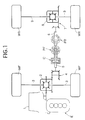
- Fig. 1 to Fig. 7 illustrate an embodiment of the present invention.
- Fig. 1 is a diagram showing a power transmission system of a four-wheel drive vehicle.
- Fig. 2 is a diagram of a hydraulic circuit relating to a hydraulic clutch.
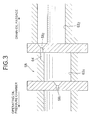
- Fig. 3 is a cross sectional view showing the structure of an orifice.
- Fig. 4 is a block diagram showing the arrangement of a control unit.
- Fig. 5 is a flow chart showing the procedure for selecting an engagement characteristic of a hydraulic clutch.
- Fig. 6 is a flow chart showing the procedure for controlling a switching valve.
- Fig. 7 is a graph of the engagement characteristics of a hydraulic clutch.
- Fig. 1 the output from an engine E as the prime mover mounted in the front part of a vehicle, is applied into a front differential 2 via a transmission 1.
- the output from the front differential 2 is transmitted to right and left front wheels WF, WF, which are driven wheels, via drive shafts 3, 3.
- the output from the engine E which has been applied to the front differential 2 is transmitted to an input shaft 5 of a hydraulic clutch C via a bevel gear 4 and the power output from an output shaft 6 of the hydraulic clutch C, is transmitted to right and left rear wheels WR, WR which are driven wheels via a bevel gear 7, a rear differential 8 and drive shafts 9, 9.
- the engagement force of the hydraulic clutch C increases according to an increase in the difference between the discharge and intake amounts of a first hydraulic pump PF and a second hydraulic pump PR, which are trochoid pumps, due to the difference in rotation between the two hydraulic pumps PF, PR.
- the first hydraulic pump PF is driven by the input shaft 5 which is operatively connected to the front wheels WF, WF
- the second hydraulic pump PR is driven by the output shaft 6 which is operatively connected to the rear wheels WR, WR.
- Fig. 2 the discharge directions of the first and second hydraulic pumps PF, PR, which are trochoid pumps, are reversed between the time when the vehicle is traveling forwards and the time when it is traveling in reverse, and the arrows of the two hydraulic pumps PF, PR in Fig. 2 show the discharge directions when the vehicle is traveling forwards.
- the first hydraulic pump PF comprises a first port 10 which becomes a discharge port when the vehicle is traveling forwards and an intake port when it is in reverse and a second port 11 which becomes an intake port when the vehicle is traveling forwards and a discharge port when it is in reverse.
- the second hydraulic pump PR comprises a third port 12 which becomes an intake port when the vehicle is traveling forwards and a discharge port when it is in reverse and a fourth port 13 which becomes a discharge port when the vehicle is traveling forwards and an intake port when it is in reverse.
- the amounts of discharge per rotation of the two hydraulic pumps PF, PR is set so that it is slightly larger for the second hydraulic pump PR (e.g. 2.5% larger) than for the first hydraulic pump PF.
- the first port 10 of the first hydraulic pump PF and the third port 12 of the second hydraulic pump PR are connected via a first oil passage 14, and the second port 11 of the first hydraulic pump PF and the fourth port 13 of the second hydraulic pump PR are connected via a second oil passage 15. Moreover, a third oil passage 16 is connected to the first oil passage 14 and a fourth oil passage 17 is connected to the second oil passage 15.
- the hydraulic clutch C comprises an outer clutch portion 20 fixed to the input shaft 5, an inner clutch portion 21 fixed to the output shaft 6 whose front end is coaxially fitted into the rear end of the input shaft 5 in a relatively rotatable manner, multiple clutch plates 22 which are spline-connected to the inner circumference of the outer clutch portion 20, and multiple clutch plates 23 which are spline-connected to the outer circumference of the inner clutch portion 21.
- the clutch plates 22 and 23 are superimposed so that they can make contact with each other.
- the clutch plates 22 and 23 are pressed by a pressure plate 24 in a direction such that they make contact with each other and are engaged by means of friction.
- a clutch piston 26 is provided on the reverse surface of the pressure plate 24 via a roller bearing 25, the clutch piston 26 fits in a slidable manner in a clutch cylinder 28 provided on a fixed casing 27, and a hydraulic oil pressure chamber 29 is formed between the casing 27 and the clutch piston 26.
- the engagement force of the hydraulic clutch C that is, the amount of torque transmitted from the engine E to the two rear wheels WR, WR is therefore determined by the oil pressure of the hydraulic oil pressure chamber 29.
- a hydraulic oil supply passage 31 is connected to the hydraulic oil pressure chamber 29 via a choke type constriction 30, the third oil passage 16 is connected to the hydraulic oil supply passage 31 via a first one-way valve 32 which only allows the flow of hydraulic oil towards the hydraulic oil supply passage 31, and the fourth oil passage 17 is connected to the hydraulic oil supply passage 31 via a second one-way valve 33 which only allows the flow of hydraulic oil towards the hydraulic oil supply passage 31.
- a fifth oil passage 35 leading to an oil tank 36 and the third oil passage 16 are connected via a third one-way valve 34 which only allows the flow of hydraulic oil from the fifth oil passage 35 to the third oil passage 16.
- the hydraulic oil in the hydraulic oil pressure chamber 29 is drained through a drain oil passage 37, and this drain oil passage 37 is connected to a lubricating oil passage 38 which is provided coaxially on the output shaft 6.
- the lubricating oil passage 38 is connected to the inside of the hydraulic clutch C via multiple oil pores 39 provided on the side wall of the output shaft 6 and the interior of the hydraulic clutch C is lubricated by the hydraulic oil which has been drained into the drain oil passage 37.
- the hydraulic oil supply passage 31 and the drain oil passage 37 are connected via a first relief valve 40, and a thermoswitch 41 is attached to the first relief valve 40, and opens the first relief valve 40 in response to an increase in the oil temperature.
- a spool valve 44, a fourth one-way valve 45 and a fifth one-way valve 46 are provided in the second oil passage 15.
- the spool valve 44 comprises a valve housing 52 having a first input port 47, a first output port 48, a second input port 49, a second output port 50 and an escape port 51.
- a spool 53 fits in a slidable manner in the valve housing 52 to make the oil pressure of the second input port 49 work on one end thereof in the axial direction and the oil pressure of the first input port 47 on the other end thereof in the axial direction, and a spring 54 is provided between the valve housing 52 and the spool 53 and exhibits a spring force that forces the spool 53 to one side in the axial direction.
- the first input port 47 is linked to the second port 11 of the first hydraulic pump PF and the first output port 48 is connected to the fourth port 13 of the second hydraulic pump PR via the fourth one-way valve 45.
- the second input port 49 is linked to the fourth port 13 of the second hydraulic pump PR, and the second output port 50 is connected to the second port 11 of the first hydraulic pump PF via the fifth one-way valve 46.
- the escape port 51 is provided on the valve housing 52 so that it is linked to the second input port 49 while the second input port 49 and the second output port 50 are linked to each other, and the escape port 51 is also linked to the drain oil passage 37.
- the fourth one-way valve 45 only allows the flow of hydraulic oil from the first output port 48 to the fourth port 13 and the fifth one-way valve 46 only allows the flow of hydraulic oil from the second output port 50 to the second port 11.
- a point between the second output port 50 and the fifth one-way valve 46 is linked to the oil tank 36 and the fifth oil passage 35 via a sixth oil passage 55, and the fourth oil passage 17 is linked to the second oil passage 15 between the second port 11 of the first hydraulic pump PF and the first input port 47 of the spool valve 44.
- the spool 53 when the vehicle is in reverse, that is, when the second port 11 of the first hydraulic pump PF is discharging hydraulic oil, the spool 53 is positioned rightwards as shown in the figure, the first input port 47 is linked to the first output port 48, while the second output port 50 and the escape port 51 are cut off from the second input port 49; when the vehicle is traveling forwards, that is, when the fourth port 13 of the second hydraulic pump PR is discharging hydraulic oil, the spool 53 is positioned leftwards, the second output port 50 and the escape port 51 are linked to the second input port 49 while the first output port 48 is cut off from the first input port 47.
- the engagement force of the hydraulic clutch C is controlled by an engagement force control means 57, and the engagement force control means 57 comprises an orifice 58 provided on the drain oil passage 37 for draining the hydraulic oil from the hydraulic oil pressure chamber 29 in the hydraulic clutch C, a switching valve 59 which is a normally open type electromagnetic valve provided between the orifice 58 and the hydraulic oil pressure chamber 29, a by-pass 60 joining the orifice 58 to the hydraulic oil pressure chamber 29 when bypassing the switching valve 59, a second relief valve 61 provided on the by-pass 60 so as to open in the event that the oil pressure on the hydraulic oil pressure chamber 29 side reaches a predetermined level or higher, and a normally closed type electromagnetic valve 62 provided between the hydraulic oil pressure chamber 29 and the drain oil passage 37.
- the engagement force control means 57 comprises an orifice 58 provided on the drain oil passage 37 for draining the hydraulic oil from the hydraulic oil pressure chamber 29 in the hydraulic clutch C, a switching valve 59 which is a normally open type electromagnetic valve provided between the orifice 58 and the
- the orifice 58 is formed from a first orifice 58 1 on the upstream side (the side of the hydraulic oil pressure chamber 29) and a second orifice 58 2 on the downstream side (the side of the drain oil passage 37).
- An upstream side oil passage 63 1 provided between the first and second orifices 58 1 , 58 2 is formed such that it is positioned at a level slightly lower than that of a downstream side oil passage 63 2 which is separated from the upstream side oil passage 63 1 by the second orifice 58 2 , and the second orifice 58 2 is provided to stretch between an air pocket 64 formed on the upper part of the upstream oil passage 63 1 and the vicinity of the upper wall of the downstream side oil passage 63 2 .
- the switching valve 59 switches between a valve open state, in which hydraulic oil is discharged from the hydraulic oil pressure chamber 29 while regulating the amount of discharge by means of the orifice 58 so as to reduce the responsiveness of torque transmission of the hydraulic clutch C, and a valve closed state, in which the hydraulic oil is prevented from discharging from the hydraulic oil pressure chamber 29 to enhance the responsiveness of torque transmission of the hydraulic clutch C.
- the normally closed type electromagnetic valve 62 discharges hydraulic oil from the hydraulic oil pressure chamber 29 without restriction when it is open so that the hydraulic clutch C is disengaged and a two-wheel drive state using the right and left front wheels WF, WF alone is brought about.
- the opening and closing motion of the switching valve 59 and the opening and closing motion of the normally closed type electromagnetic valve 62 in the engagement force control means 57 are controlled by the control unit 65, and in order to operate the switching valve 59 and the normally closed type electromagnetic valve 62, the control unit 65 receives inputs relating to the front wheel velocity FV detected by a front wheel velocity detecting means 66, the rear wheel velocity RV detected by a rear wheel velocity detecting means 67, the degree of throttle opening ⁇ TH detected by a degree of throttle opening detecting means 68, the presence of an antilock brake motion detected by an ABS detecting means 69 and a switch signal from a switch 70.
- the control unit 65 comprises a slip detecting means 71, a vehicle body speed detecting means 72, a starting status detecting means 73, a counter 74, a comparator 75, an engagement characteristic selection means 76, an AND gate 77, a comparator 78, a NOT circuit 79, a comparator 80, a NOT circuit 82 and driving means 83, 84.
- the slip detecting means 71 detects the slip in a front wheel WF based on the front wheel velocity FV detected by the front wheel velocity detecting means 66 and the rear wheel velocity RV detected by the rear wheel velocity detecting means 67, and it determines that slip is present in the front wheel WF when the difference between the front wheel velocity FV and the rear wheel velocity RV is at least at a predetermined level.
- the predetermined level is set to be larger (for example, 3 km/h) than the difference in velocity caused by the difference between the inside wheels of the front wheels WF and the rear wheels WR when the vehicle is turning, and mistakenly determining that slip is occurring in the front wheels WF when the vehicle is turning on a road surface having a high coefficient of friction can therefore be avoided.
- the vehicle body speed detecting means 72 detects the vehicle body speed based on the rear wheel velocity RV detected by the rear wheel velocity detecting means 67.
- the starting status detecting means 73 detects the starting status of the vehicle based on the vehicle body speed detected by the vehicle body speed detecting means 72, and determines that the vehicle has started when there is a change in the vehicle body speed, for example, from 5 km/h or less to 20 km/h or more, then outputting a high level signal.
- the counter 74 counts the number of times that the starting status is detected by the starting status detecting means 73, and the count number of the counter 74 is reset in the event that slip is detected in a front wheel WF by the slip detecting means 71.
- the comparator 75 outputs a high level signal in the event that the count number N obtained by the counter 74 exceeds a predetermined number N 0 set by a reference terminal 85, and the predetermined number N 0 is set to be, for example, 5 times.
- the engagement characteristic selecting means 76 selects an engagement characteristic for the hydraulic clutch C based on the outputs from the slip detecting means 71 and the comparator 75.
- this engagement characteristic selecting means 76 there are multiple predetermined engagement characteristics wherein the responsiveness of the torque transmission by the hydraulic clutch C varies, that is, the first and second engagement characteristics in the present embodiment; the first engagement characteristic enhances the responsiveness of the torque transmission by the hydraulic clutch C by increasing the oil pressure of the hydraulic pressure chamber 29 so as to increase the engagement force relative to the difference in rotation between the first and second hydraulic pumps PF, PR, and the second engagement characteristic reduces the responsiveness of the torque transmission by the hydraulic clutch C by decreasing the oil pressure of the hydraulic pressure chamber 29 so as to decrease the engagement force relative to the difference in rotation between the first and second hydraulic pumps PF, PR.
- the engagement characteristic selecting means 76 thus outputs a high level signal when selecting the first engagement characteristic by setting a flag F to '1', which shows whether or not the first engagement characteristic is selected, and outputs a low level signal when selecting the second engagement characteristic by setting the flag F to '0'.
- the processing in the engagement characteristic selecting means 76 and the counter 74 is carried out by the procedure shown in Fig. 5, and when it is confirmed in step S1 that the slip detecting means 71 is detecting a slip state, the flag F is set to '1' in step S2. The flag F is set to '1' in the initial state.
- step S3 the count number of the counter 74 is reset to '0', and the procedure continues on to step S4.
- the procedure moves to step S4 from step S1 bypassing steps S2 and S3.
- N N 0
- the procedure continues on to step S7 from step S6 and the flag F is set to '0'.
- the output from the engagement characteristic selecting means 76 is input into an AND gate 77 and the output signals from NOT circuits 79, 82 and the comparator 80 are also input into the AND gate 77.
- the NOT circuit 79 is for inverting the output from the comparator 78, and the comparator 78 outputs a high level signal when the vehicle body speed detected by the vehicle body speed detecting means 72 exceeds a threshold value for the vehicle body speed set by a reference terminal 86, for example, 20 km/h.
- the NOT circuit 79 therefore inputs a high level signal into the AND gate 77 when the vehicle body speed is not higher than the threshold value for the vehicle body speed (for example, 20 km/h).
- the comparator 80 inputs a high level signal into the AND gate 77 when the degree of throttle opening 2 TH detected by the degree of throttle opening detecting means 68 exceeds a threshold value for the degree of throttle opening set by a reference terminal 87, for example, 1/6 open, that is to say, when the throttle pedal is depressed.
- the NOT circuit 82 inverts the output signal from the ABS detecting means 69, and since the ABS detecting means 69 outputs a high level signal in an antilock brake operational state, the NOT circuit 82 inputs a high level signal into the AND gate 77 in a non-antilock brake operational state.
- the output from the AND gate 77 is input into a driving means 83 for driving the switching valve 59, and when the output from the AND gate 77 is at a high level the driving means 83 closes the switching valve 59.
- step S11 the ABS detecting means 69 is detecting an antilock brake operational state
- step S12 the switching valve 59 is opened in step S12, and when the ABS detecting means 69 is not detecting an antilock braking operational state, the procedure continues on to step S13.
- step S13 it is determined whether or not the degree of throttle opening ⁇ TH detected by the degree of throttle opening detecting means 68 is at or below the threshold for the degree of throttle opening; when the degree of throttle opening ⁇ TH is not higher than the threshold for the degree of throttle opening, the procedure continues on to step S12 from step S13, and when the degree of throttle opening ⁇ TH is higher than the threshold for the degree of throttle opening the procedure continues on to step S14 from step S13.
- step S14 it is determined whether or not the vehicle body speed detected by the vehicle body speed detecting means 72 exceeds a threshold value for the vehicle body speed; when the vehicle body speed is higher than the threshold value for the vehicle body speed, the procedure continues on to step S12 from step S14, and when the vehicle body speed is not higher than the threshold value for the vehicle body speed, the procedure continues on step S15 from step S14.
- the driving means 84 opens the normally closed electromagnetic valve 62 according to a switch signal from the switch 70 when selecting the two-wheel drive state.
- the driving force of the engine E is transmitted to the right and left front wheels WF, WF via the transmission 1, the front differential 2 and the drive shafts 3,3 so that both the right and left front wheels WF, WF are directly driven by the engine E.
- the driving force of the engine E is transmitted from the front differential 2 to the first hydraulic pump PF via the bevel gear 4 and the input shaft 5 so that the first hydraulic pump PF is driven by being operatively connected to the right and left front wheels WF, WF.
- the second hydraulic pump PR is driven by being operatively connected to both the rear wheels WR, WR.
- the oil discharged from the first hydraulic pump PF is taken into the third port 12 of the second hydraulic pump PR by the operation of the second hydraulic pump PR; as a result of the discharge pressure of the second hydraulic pump PR, the spool valve 44 attains a state in which the second input port 49 and the second output port 50 are linked together and the oil discharged from the second hydraulic pump PR is taken into the first hydraulic pump PF via the fifth one way valve 46.
- the engagement force of the hydraulic clutch C increases as the difference between the discharge and the intake amounts of the two hydraulic pumps PF, PR increases, and when it attains a state in which the difference in rotation between the front wheels WF and the rear wheels WR is substantially '0', for example, a state in which the vehicle is traveling in a straight line on an asphalt road surface, hydraulic oil is not supplied to the hydraulic oil pressure chamber 29 of the hydraulic clutch C and torque distribution to the rear wheels WR is stopped.
- the engagement force of the hydraulic clutch C is controlled by the engagement force control means 57 by selecting from multiple engagement characteristics (two in this embodiment), in which the responsiveness of the torque transmission by the hydraulic clutch C is varied, according to the driving conditions.
- the maximum value T 2 for the transmission torque is determined by the predetermined relief pressure of the first relief valve 40.
- the engagement force control means 57 thus controls the engagement force of the hydraulic clutch C by selecting the engagement characteristic according to the driving conditions of the vehicle and, therefore, the responsiveness of the torque transmission by the hydraulic clutch C can be controlled according to the driving conditions of the vehicle.
- the engagement force control means 57 may include the orifice 58 provided in the drain oil passage 37 and the switching valve 59 provided between the orifice 58 and the hydraulic oil pressure chamber 29, and thus the arrangement of the engagement force control means 57 can be simplified.
- the engagement force control means 57 includes the by-pass 60 which joins the orifice 58 to the hydraulic oil pressure chamber 29 when bypassing the switching valve 59, and the second relief valve 61 which is provided on the by-pass 60 so that it opens in the event that the oil pressure of the hydraulic oil pressure chamber 29 reaches at least a predetermined level.
- the upper limit for the oil pressure of the hydraulic oil pressure chamber 29 in a state in which the responsiveness of the torque transmission by the hydraulic clutch C is enhanced by closure of the switching valve 59, that is to say, the upper limit T 1 for the torque transmitted by the hydraulic clutch C (see Fig. 7) is determined by the valve opening pressure for the second relief valve 61, and thus excess torque transmission by the hydraulic clutch C in a state in which there is enhanced responsiveness, can be prevented by a simple arrangement.
- the control unit 65 for controlling the opening and closing motions of the switching valve 59 in the engagement force control means 57 comprises the slip detecting means 71 for detecting slip in a front wheel WF, a starting status detecting means 73 for detecting the starting status of the vehicle, the counter 74 for counting the number of times that the starting status is detected in the starting status detecting means 73 and the engagement characteristic selecting means 76 for selecting an engagement characteristic in which the engagement force of the hydraulic clutch C is increased relative to the difference in rotation between the first and second hydraulic pumps PF, PR until the count number N of the counter 74 reaches a predetermined number N 0 after slip is detected by the slip detecting means 71.
- the responsiveness of the torque transmission by the hydraulic clutch C is therefore enhanced until the number of times N that the starting status is detected by the starting status detecting means 73, reaches a predetermined number N 0 . That is to say, when slip occurs in a front wheel WF on a road surface having a low coefficient of friction such as a snow-covered road, the responsiveness of the torque transmission is enhanced until the number N of times that the vehicle has started reaches a predetermined number N 0 by assuming that the vehicle will continue to travel on a road surface having a low coefficient of friction for a while, and thus the mobility of the vehicle can be enhanced.
- the responsiveness of the torque transmission is enhanced until the number of times N that the vehicle has started after slip has recurred reaches a predetermined number N 0 , and thus it can deal with continuous travel on a road surface having a low coefficient of friction. Furthermore, when leaving a road surface having a low coefficient of friction, the engagement force of the hydraulic clutch C is controlled so as to employ an engagement characteristic having low responsiveness in order to suit a normal paved road, etc. unless the slip occurs even when the vehicle has started a predetermined number N 0 of times.
- the braking force When braking the vehicle, the braking force is generally distributed so that it is higher on the front wheel WF side than on the rear wheel WR side, and therefore the front wheels WF lock before the rear wheels WR during rapid braking. Moreover, since engine braking during constant speed forward travel is applied only to the front wheels WF, the rotation of the front wheels WF transiently becomes lower than that of the rear wheels WR. In such a case, the amount discharged from the second hydraulic pump PR exceeds the amount taken in by the first hydraulic pump PF and excess hydraulic oil is discharged into the second oil passage 15. In the case where the front wheels WF are completely locked, the total amount of discharge from the second hydraulic pump PR becomes excessive.
- the predetermined number N 0 for the start number it is possible to change the predetermined number N 0 for the start number appropriately, and the predetermined number N 0 may be changed according to the front wheel driving force when the front wheels slip.
- the front wheels WF are directly driven by the engine E and the rear wheels WR are driven via the hydraulic clutch C, but the present invention can also be applied to a four-wheel drive vehicle in which the rear wheels WR are driven directly by the engine E and the front wheels WF are driven via the hydraulic clutch C.
- the responsiveness of the torque transmission by the hydraulic clutch can be controlled according to the driving conditions of the vehicle. Further the arrangement of the engagement force control means can be simplified.
- an upper limit for the oil pressure of the hydraulic oil pressure chamber in a state in which the responsiveness of the torque transmission by the hydraulic clutch is enhanced by closure of the switching valve that is, an upper limit for the torque transmitted by the hydraulic clutch is determined by the valve opening pressure for the relief valve, and thus excess torque transmission by the hydraulic clutch in a state in which there is enhanced responsiveness can be prevented by a simple arrangement.
- the responsiveness of the torque transmission is enhanced until the number of times that the vehicle has started reaches a predetermined number by assuming that the vehicle will continue to travel on the road surface having a low coefficient of friction for a while, and thus the mobility of the vehicle can be enhanced.
- the responsiveness of the torque transmission is enhanced until the number of times that the vehicle has started after the slip has recurred reaches a predetermined number, and thus continuous travel on a road surface having a low coefficient of friction can be dealt with.
- the engagement force of the hydraulic clutch is controlled to employ an engagement characteristic having low responsiveness in order to suit a normal paved road, etc. unless the aforementioned slip is caused even when the vehicle repeats starting a predetermined number of times.
- a driving force control device for a four-wheel drive vehicle including one pair of front or rear driven wheels which are driven directly by a prime mover and another pair of front or rear driven wheels which are driven via a hydraulic clutch, a first hydraulic pump which is driven by being operatively connected to the one pair of driven wheels, and a second hydraulic pump which is driven by being operatively connected to the other pair of driven wheels.
- the engagement force of the hydraulic clutch is controllable based on the difference in rotation of the first and second hydraulic pumps.
- the torque transmission to the other pair of the front or rear driven wheels can thus be controlled according to the driving conditions of the vehicle.
- the engagement force of the hydraulic clutch is controlled by an engagement force control unit by selecting from multiple engagement characteristics, in which the responsiveness of the torque transmitted by the hydraulic clutch is varied, according to the driving conditions of the vehicle.
Landscapes
- Engineering & Computer Science (AREA)
- Chemical & Material Sciences (AREA)
- Combustion & Propulsion (AREA)
- Transportation (AREA)
- Mechanical Engineering (AREA)
- Arrangement And Driving Of Transmission Devices (AREA)
- Arrangement And Mounting Of Devices That Control Transmission Of Motive Force (AREA)
- Hydraulic Clutches, Magnetic Clutches, Fluid Clutches, And Fluid Joints (AREA)
Abstract
Description
- The present invention relates to four-wheel drive vehicles comprising a pair of front or rear driven wheels which are driven directly by a prime mover and another pair of front or rear driven wheels which are driven via a hydraulic clutch. A first hydraulic pump is driven by being operatively connected to the pair of driven wheels and a second hydraulic pump is driven by being operatively connected to the other driven wheels. The engagement force of the hydraulic clutch is controllable according to the difference in rotation between the first and the second hydraulic pumps.
- The use of a two-wheel drive state using only one pair of front or rear driven wheels during normal travel is known in the art, and when a difference in rotation between the front and the rear wheels occurs both pairs of front and rear driven wheels are driven together so as to enhance the travel stability. If the difference in rotation between the front and the rear wheels is maintained so as to be small all the time, a tight brake phenomenon is caused when turning at a low speed causing the driver to feel uncomfortable and, moreover, it is necessary to increase the strength of the components used for transmitting the driving force between the front and the rear wheels, thus increasing the weight of the vehicle. It is disclosed in Japanese Patent Application Laid-open No. 3-224830 that the front wheels are always driven. When the difference in rotation between the front and the rear wheels is small, the torque transmitted to the rear wheels is made small, and the torque transmitted to the rear wheels is increased according to increases in the difference in rotation, and thus the above-mentioned problems are solved.
- However, on a road surface having a low coefficient of friction such as a snow-covered road it is desirable to increase the amount of torque transmitted to the rear wheels even when the difference in rotation between the front and the rear wheels is small, but in the above-mentioned system the amount of torque transmitted to the rear wheels remains small when the difference in rotation between the front and the rear wheels is small, and thus the objective cannot be obtained.
- The present invention has been conducted in view of the above-mentioned circumstances, and it is an object of the present invention, with regard to a four-wheel drive vehicle wherein one pair of front or rear driven wheels are always driven and the driving force of the other pair of front or rear driven wheels is controllable, to provide a driving force control device for a four-wheel drive vehicle in which the torque transmitted to the other pair of the front or rear driven wheels can be controlled according to the driving conditions of the vehicle.
- In order to achieve this object, the invention is characterized in that a driving force control device is provided for a four-wheel drive vehicle which comprises one pair of front or rear driven wheels which are driven directly by a prime mover, and another pair of front or rear driven wheels which are driven via a hydraulic clutch. A first hydraulic pump which is driven is operatively connected to the one pair of driven wheels, and a second hydraulic pump which is driven, is operatively connected to the other pair of driven wheels. The engagement force of the hydraulic clutch is controllable based on the difference between the discharge and intake amounts of the first and second hydraulic pumps due to the difference in rotation of the two hydraulic pumps, such that the engagement force increases according to an increase in the difference between the discharge and intake amounts. The driving force control device includes an engagement force control means for controlling the engagement force of the hydraulic clutch by selecting from multiple engagement characteristics in which the responsiveness of the torque transmission by the hydraulic clutch is varied according to the driving conditions of the vehicle.
- In accordance with this arrangement, since the engagement force of the hydraulic clutch is controlled by the engagement force control means by selecting an engagement characteristic according to the driving conditions of the vehicle, the responsiveness of the torque transmission by the hydraulic clutch can be controlled according to the driving conditions of the vehicle.
- The invention is further characterized in that a hydraulic oil supply passage which carries the hydraulic oil produced according to the difference between the discharge and intake amounts of the first and second hydraulic pumps, is connected to a hydraulic oil pressure chamber in the hydraulic clutch. The engagement force control means includes an orifice provided through a drain oil passage for draining the hydraulic oil in the hydraulic oil pressure chamber and a switching valve provided between the orifice and the hydraulic oil pressure chamber.
- In accordance with this arrangement of the invention, when the switching valve is open, since the engagement force of the hydraulic clutch relative to the difference in rotation between the first and second hydraulic pumps is determined by the reduction in the amount of oil drained by the orifice, the responsiveness of the torque transmission is low, whereas when the switching valve is closed, since the hydraulic oil is prevented from draining from the hydraulic oil pressure chamber, the engagement force of the hydraulic clutch relative to the difference in rotation between the first and second hydraulic pumps, increases thus enhancing the responsiveness of the torque transmission, and the arrangement of the engagement force control means can therefore be simplified.
- In addition, the engagement force control means includes a bypass connecting the orifice and the hydraulic oil pressure chamber when bypassing the switching valve, and a relief valve is provided in the bypass so that it opens in the event that the oil pressure at the side of the hydraulic oil pressure chamber, is at or above a predetermined level. In accordance with this arrangement, an upper limit for the oil pressure of the hydraulic oil pressure chamber in a state in which the responsiveness of the torque transmission by the hydraulic clutch is enhanced by closure of the switching valve, that is, an upper limit for the torque transmitted by the hydraulic clutch, is determined by the valve opening pressure for the relief valve and thus excess torque transmission by the hydraulic clutch in a state where there is enhanced responsiveness, can be prevented by a simple arrangement.
- The invention, in addition to the arrangement above is characterized in that a control unit for controlling the motion of the engagement force control means comprises a slip detecting means for detecting the slip of the one pair of front or rear driven wheels, a starting status detecting means for detecting the starting status of the vehicle, a counter for counting the number of times that the starting status is detected by the starting status detecting means, and an engagement characteristic selecting means for selecting an engagement characteristic in which the responsiveness of the torque transmission by the hydraulic clutch is enhanced until the count number of the counter reaches a predetermined number after the slip is detected by the slip detecting means.
- In accordance with this arrangement of the invention, when the slip detecting means detects the slip in one pair of the front or rear driven wheels, the responsiveness of the torque transmission by the hydraulic clutch is enhanced until the number of times that the starting status is detected by the starting status detecting means reaches a predetermined number. That is, when slip is caused in one pair of the front or rear driven wheels on a road surface having a low coefficient of friction such as a snow-covered road, the responsiveness of the torque transmission is enhanced until the number of times that the vehicle is started reaches a predetermined number by assuming that the vehicle will continue to travel on the road surface having a low coefficient of friction for a while. Thus the mobility of the vehicle can be enhanced. When slip is caused again in one pair of the front or rear driven wheels, the responsiveness of the torque transmission is enhanced until the number of times that the vehicle is started after the slip has recurred reaches the predetermined number. Thus it can deal with continuous travel on a road surface having a low coefficient of friction. Furthermore, when leaving a road surface having a low coefficient of friction, the engagement force of the hydraulic clutch is controlled so as to employ an engagement characteristic having low responsiveness corresponding to a normal paved road, etc. unless slip occurs even when the vehicle has started a predetermined number of times.
- Fig. 1 to Fig. 7 illustrate an embodiment of the present invention.
- Fig. 1 is a diagram showing a power transmission system of a four-wheel drive vehicle.
- Fig. 2 is a diagram of a hydraulic circuit relating to a hydraulic clutch.
- Fig. 3 is a cross sectional view showing the structure of an orifice.
- Fig. 4 is a block diagram showing the arrangement of a control unit.
- Fig. 5 is a flow chart showing the procedure for selecting an engagement characteristic of a hydraulic clutch.
- Fig. 6 is a flow chart showing the procedure for controlling a switching valve.
- Fig. 7 is a graph of the engagement characteristics of a hydraulic clutch.
- In Fig. 1 the output from an engine E as the prime mover mounted in the front part of a vehicle, is applied into a front differential 2 via a
transmission 1. The output from the front differential 2 is transmitted to right and left front wheels WF, WF, which are driven wheels, viadrive shafts input shaft 5 of a hydraulic clutch C via abevel gear 4 and the power output from anoutput shaft 6 of the hydraulic clutch C, is transmitted to right and left rear wheels WR, WR which are driven wheels via abevel gear 7, arear differential 8 anddrive shafts - That is, while the right and left front wheels WF, WF, which are one pair of front or rear driven wheels, are driven directly by the engine E, the right and left rear wheels WR, WR which are the other pair of front or rear driven wheels, are driven via the hydraulic clutch C.
- The engagement force of the hydraulic clutch C increases according to an increase in the difference between the discharge and intake amounts of a first hydraulic pump PF and a second hydraulic pump PR, which are trochoid pumps, due to the difference in rotation between the two hydraulic pumps PF, PR. The first hydraulic pump PF is driven by the
input shaft 5 which is operatively connected to the front wheels WF, WF, and the second hydraulic pump PR is driven by theoutput shaft 6 which is operatively connected to the rear wheels WR, WR. - In Fig. 2 the discharge directions of the first and second hydraulic pumps PF, PR, which are trochoid pumps, are reversed between the time when the vehicle is traveling forwards and the time when it is traveling in reverse, and the arrows of the two hydraulic pumps PF, PR in Fig. 2 show the discharge directions when the vehicle is traveling forwards.
- The first hydraulic pump PF comprises a
first port 10 which becomes a discharge port when the vehicle is traveling forwards and an intake port when it is in reverse and a second port 11 which becomes an intake port when the vehicle is traveling forwards and a discharge port when it is in reverse. The second hydraulic pump PR comprises athird port 12 which becomes an intake port when the vehicle is traveling forwards and a discharge port when it is in reverse and afourth port 13 which becomes a discharge port when the vehicle is traveling forwards and an intake port when it is in reverse. The amounts of discharge per rotation of the two hydraulic pumps PF, PR is set so that it is slightly larger for the second hydraulic pump PR (e.g. 2.5% larger) than for the first hydraulic pump PF. - The
first port 10 of the first hydraulic pump PF and thethird port 12 of the second hydraulic pump PR are connected via afirst oil passage 14, and the second port 11 of the first hydraulic pump PF and thefourth port 13 of the second hydraulic pump PR are connected via asecond oil passage 15. Moreover, athird oil passage 16 is connected to thefirst oil passage 14 and afourth oil passage 17 is connected to thesecond oil passage 15. - The hydraulic clutch C comprises an
outer clutch portion 20 fixed to theinput shaft 5, aninner clutch portion 21 fixed to theoutput shaft 6 whose front end is coaxially fitted into the rear end of theinput shaft 5 in a relatively rotatable manner,multiple clutch plates 22 which are spline-connected to the inner circumference of theouter clutch portion 20, andmultiple clutch plates 23 which are spline-connected to the outer circumference of theinner clutch portion 21. Theclutch plates - The
clutch plates pressure plate 24 in a direction such that they make contact with each other and are engaged by means of friction. A clutch piston 26 is provided on the reverse surface of thepressure plate 24 via a roller bearing 25, the clutch piston 26 fits in a slidable manner in aclutch cylinder 28 provided on a fixedcasing 27, and a hydraulic oil pressure chamber 29 is formed between thecasing 27 and the clutch piston 26. - The engagement force of the hydraulic clutch C, that is, the amount of torque transmitted from the engine E to the two rear wheels WR, WR is therefore determined by the oil pressure of the hydraulic oil pressure chamber 29.
- A hydraulic oil supply passage 31 is connected to the hydraulic oil pressure chamber 29 via a
choke type constriction 30, thethird oil passage 16 is connected to the hydraulic oil supply passage 31 via a first one-way valve 32 which only allows the flow of hydraulic oil towards the hydraulic oil supply passage 31, and thefourth oil passage 17 is connected to the hydraulic oil supply passage 31 via a second one-way valve 33 which only allows the flow of hydraulic oil towards the hydraulic oil supply passage 31. Afifth oil passage 35 leading to anoil tank 36 and thethird oil passage 16 are connected via a third one-way valve 34 which only allows the flow of hydraulic oil from thefifth oil passage 35 to thethird oil passage 16. - The hydraulic oil in the hydraulic oil pressure chamber 29 is drained through a
drain oil passage 37, and thisdrain oil passage 37 is connected to a lubricatingoil passage 38 which is provided coaxially on theoutput shaft 6. The lubricatingoil passage 38 is connected to the inside of the hydraulic clutch C viamultiple oil pores 39 provided on the side wall of theoutput shaft 6 and the interior of the hydraulic clutch C is lubricated by the hydraulic oil which has been drained into thedrain oil passage 37. - The hydraulic oil supply passage 31 and the
drain oil passage 37 are connected via afirst relief valve 40, and athermoswitch 41 is attached to thefirst relief valve 40, and opens thefirst relief valve 40 in response to an increase in the oil temperature. - A
spool valve 44, a fourth one-way valve 45 and a fifth one-way valve 46 are provided in thesecond oil passage 15. Thespool valve 44 comprises avalve housing 52 having afirst input port 47, afirst output port 48, asecond input port 49, asecond output port 50 and anescape port 51. Aspool 53 fits in a slidable manner in thevalve housing 52 to make the oil pressure of thesecond input port 49 work on one end thereof in the axial direction and the oil pressure of thefirst input port 47 on the other end thereof in the axial direction, and a spring 54 is provided between thevalve housing 52 and thespool 53 and exhibits a spring force that forces thespool 53 to one side in the axial direction. - The
first input port 47 is linked to the second port 11 of the first hydraulic pump PF and thefirst output port 48 is connected to thefourth port 13 of the second hydraulic pump PR via the fourth one-way valve 45. Thesecond input port 49 is linked to thefourth port 13 of the second hydraulic pump PR, and thesecond output port 50 is connected to the second port 11 of the first hydraulic pump PF via the fifth one-way valve 46. Theescape port 51 is provided on thevalve housing 52 so that it is linked to thesecond input port 49 while thesecond input port 49 and thesecond output port 50 are linked to each other, and theescape port 51 is also linked to thedrain oil passage 37. - The fourth one-
way valve 45 only allows the flow of hydraulic oil from thefirst output port 48 to thefourth port 13, and the fifth one-way valve 46 only allows the flow of hydraulic oil from thesecond output port 50 to the second port 11. - A point between the
second output port 50 and the fifth one-way valve 46 is linked to theoil tank 36 and thefifth oil passage 35 via asixth oil passage 55, and thefourth oil passage 17 is linked to thesecond oil passage 15 between the second port 11 of the first hydraulic pump PF and thefirst input port 47 of thespool valve 44. - In the
spool valve 44, when the vehicle is in reverse, that is, when the second port 11 of the first hydraulic pump PF is discharging hydraulic oil, thespool 53 is positioned rightwards as shown in the figure, thefirst input port 47 is linked to thefirst output port 48, while thesecond output port 50 and theescape port 51 are cut off from thesecond input port 49; when the vehicle is traveling forwards, that is, when thefourth port 13 of the second hydraulic pump PR is discharging hydraulic oil, thespool 53 is positioned leftwards, thesecond output port 50 and theescape port 51 are linked to thesecond input port 49 while thefirst output port 48 is cut off from thefirst input port 47. - The engagement force of the hydraulic clutch C is controlled by an engagement force control means 57, and the engagement force control means 57 comprises an
orifice 58 provided on thedrain oil passage 37 for draining the hydraulic oil from the hydraulic oil pressure chamber 29 in the hydraulic clutch C, a switchingvalve 59 which is a normally open type electromagnetic valve provided between theorifice 58 and the hydraulic oil pressure chamber 29, a by-pass 60 joining theorifice 58 to the hydraulic oil pressure chamber 29 when bypassing the switchingvalve 59, asecond relief valve 61 provided on the by-pass 60 so as to open in the event that the oil pressure on the hydraulic oil pressure chamber 29 side reaches a predetermined level or higher, and a normally closed typeelectromagnetic valve 62 provided between the hydraulic oil pressure chamber 29 and thedrain oil passage 37. - In Fig. 3 the
orifice 58 is formed from afirst orifice 581 on the upstream side (the side of the hydraulic oil pressure chamber 29) and asecond orifice 582 on the downstream side (the side of the drain oil passage 37). An upstream side oil passage 631 provided between the first andsecond orifices second orifice 582, and thesecond orifice 582 is provided to stretch between anair pocket 64 formed on the upper part of the upstream oil passage 631 and the vicinity of the upper wall of the downstream side oil passage 632. - In accordance with the
orifice 58 having such an arrangement, even if air which flows back in thedrain oil passage 37 from the inside of the hydraulic clutch C, passes through thesecond orifice 582, it will be trapped in theair pocket 64 and thus the back flow of air into the hydraulic oil pressure chamber 29 can be prevented. - The switching
valve 59 switches between a valve open state, in which hydraulic oil is discharged from the hydraulic oil pressure chamber 29 while regulating the amount of discharge by means of theorifice 58 so as to reduce the responsiveness of torque transmission of the hydraulic clutch C, and a valve closed state, in which the hydraulic oil is prevented from discharging from the hydraulic oil pressure chamber 29 to enhance the responsiveness of torque transmission of the hydraulic clutch C. Moreover, the normally closed typeelectromagnetic valve 62 discharges hydraulic oil from the hydraulic oil pressure chamber 29 without restriction when it is open so that the hydraulic clutch C is disengaged and a two-wheel drive state using the right and left front wheels WF, WF alone is brought about. - In Fig. 4, the opening and closing motion of the switching
valve 59 and the opening and closing motion of the normally closed typeelectromagnetic valve 62 in the engagement force control means 57 are controlled by thecontrol unit 65, and in order to operate the switchingvalve 59 and the normally closed typeelectromagnetic valve 62, thecontrol unit 65 receives inputs relating to the front wheel velocity FV detected by a front wheelvelocity detecting means 66, the rear wheel velocity RV detected by a rear wheelvelocity detecting means 67, the degree of throttle opening TH detected by a degree of throttleopening detecting means 68, the presence of an antilock brake motion detected by anABS detecting means 69 and a switch signal from aswitch 70. - The
control unit 65 comprises aslip detecting means 71, a vehicle bodyspeed detecting means 72, a startingstatus detecting means 73, acounter 74, acomparator 75, an engagement characteristic selection means 76, an ANDgate 77, acomparator 78, aNOT circuit 79, acomparator 80, aNOT circuit 82 and driving means 83, 84. - The
slip detecting means 71 detects the slip in a front wheel WF based on the front wheel velocity FV detected by the front wheelvelocity detecting means 66 and the rear wheel velocity RV detected by the rear wheelvelocity detecting means 67, and it determines that slip is present in the front wheel WF when the difference between the front wheel velocity FV and the rear wheel velocity RV is at least at a predetermined level. The predetermined level is set to be larger (for example, 3 km/h) than the difference in velocity caused by the difference between the inside wheels of the front wheels WF and the rear wheels WR when the vehicle is turning, and mistakenly determining that slip is occurring in the front wheels WF when the vehicle is turning on a road surface having a high coefficient of friction can therefore be avoided. - The vehicle body
speed detecting means 72 detects the vehicle body speed based on the rear wheel velocity RV detected by the rear wheelvelocity detecting means 67. - The starting
status detecting means 73 detects the starting status of the vehicle based on the vehicle body speed detected by the vehicle bodyspeed detecting means 72, and determines that the vehicle has started when there is a change in the vehicle body speed, for example, from 5 km/h or less to 20 km/h or more, then outputting a high level signal. - The counter 74 counts the number of times that the starting status is detected by the starting
status detecting means 73, and the count number of thecounter 74 is reset in the event that slip is detected in a front wheel WF by theslip detecting means 71. - The
comparator 75 outputs a high level signal in the event that the count number N obtained by thecounter 74 exceeds a predetermined number N0 set by areference terminal 85, and the predetermined number N0 is set to be, for example, 5 times. - The engagement
characteristic selecting means 76 selects an engagement characteristic for the hydraulic clutch C based on the outputs from theslip detecting means 71 and thecomparator 75. In this engagement characteristic selecting means 76 there are multiple predetermined engagement characteristics wherein the responsiveness of the torque transmission by the hydraulic clutch C varies, that is, the first and second engagement characteristics in the present embodiment; the first engagement characteristic enhances the responsiveness of the torque transmission by the hydraulic clutch C by increasing the oil pressure of the hydraulic pressure chamber 29 so as to increase the engagement force relative to the difference in rotation between the first and second hydraulic pumps PF, PR, and the second engagement characteristic reduces the responsiveness of the torque transmission by the hydraulic clutch C by decreasing the oil pressure of the hydraulic pressure chamber 29 so as to decrease the engagement force relative to the difference in rotation between the first and second hydraulic pumps PF, PR. The engagement characteristic selecting means 76 thus outputs a high level signal when selecting the first engagement characteristic by setting a flag F to '1', which shows whether or not the first engagement characteristic is selected, and outputs a low level signal when selecting the second engagement characteristic by setting the flag F to '0'. - The processing in the engagement
characteristic selecting means 76 and thecounter 74 is carried out by the procedure shown in Fig. 5, and when it is confirmed in step S1 that theslip detecting means 71 is detecting a slip state, the flag F is set to '1' in step S2. The flag F is set to '1' in the initial state. - In the subsequent step S3, the count number of the
counter 74 is reset to '0', and the procedure continues on to step S4. On the other hand, when it is determined in step S1 that theslip detecting means 71 is not detecting a slip state, the procedure moves to step S4 from step S1 bypassing steps S2 and S3. - In step S4, it is determined whether or not the flag F is set to '1'; if F = 1 the count number N of the
counter 74 is increased by '1' in step S5, and in the subsequent step S6 it is determined whether or not the count number N exceeds the predetermined number N0. When it is confirmed that N > N0, the procedure continues on to step S7 from step S6 and the flag F is set to '0'. - In accordance with the procedure shown in Fig. 5, the engagement characteristic selecting means 76 outputs a high level signal by setting the flag F to '1' in the initial state, and in accordance with the input of a high level signal from the
comparator 75, that is, in the event that the count number N for the starting status of the vehicle exceeds a predetermined number N0, the second engagement characteristic (F = 0) is selected to set the output to a low level, and in the event that theslip detecting means 71 detects slip, the first engagement characteristic (F = 1) is selected to set the output to a high level. - In the procedure, until slip is detected for the first time, the first engagement characteristic (F = 1) is selected up to the time at which the count number N for the starting status of the vehicle reaches the predetermined number N0, and thus the first engagement characteristic in which the responsiveness of the torque transmission by the hydraulic clutch C is enhanced is selected for starting until the predetermined number N0 is reached, during which time the state of the road surface cannot be determined.
- The output from the engagement
characteristic selecting means 76 is input into an ANDgate 77 and the output signals fromNOT circuits comparator 80 are also input into the ANDgate 77. - The
NOT circuit 79 is for inverting the output from thecomparator 78, and thecomparator 78 outputs a high level signal when the vehicle body speed detected by the vehicle bodyspeed detecting means 72 exceeds a threshold value for the vehicle body speed set by areference terminal 86, for example, 20 km/h. TheNOT circuit 79 therefore inputs a high level signal into the ANDgate 77 when the vehicle body speed is not higher than the threshold value for the vehicle body speed (for example, 20 km/h). - The
comparator 80 inputs a high level signal into the ANDgate 77 when the degree of throttle opening 2TH detected by the degree of throttleopening detecting means 68 exceeds a threshold value for the degree of throttle opening set by areference terminal 87, for example, 1/6 open, that is to say, when the throttle pedal is depressed. - The
NOT circuit 82 inverts the output signal from theABS detecting means 69, and since the ABS detecting means 69 outputs a high level signal in an antilock brake operational state, theNOT circuit 82 inputs a high level signal into the ANDgate 77 in a non-antilock brake operational state. - The output from the AND
gate 77 is input into a driving means 83 for driving the switchingvalve 59, and when the output from the ANDgate 77 is at a high level the driving means 83 closes the switchingvalve 59. - The processing in the AND
gate 77 and the driving means 83 is carried out according to the procedure shown in Fig. 6; when it is confirmed in step S11 that theABS detecting means 69 is detecting an antilock brake operational state, the switchingvalve 59 is opened in step S12, and when theABS detecting means 69 is not detecting an antilock braking operational state, the procedure continues on to step S13. - In step S13, it is determined whether or not the degree of throttle opening TH detected by the degree of throttle
opening detecting means 68 is at or below the threshold for the degree of throttle opening; when the degree of throttle opening TH is not higher than the threshold for the degree of throttle opening, the procedure continues on to step S12 from step S13, and when the degree of throttle opening TH is higher than the threshold for the degree of throttle opening the procedure continues on to step S14 from step S13. - In step S14 it is determined whether or not the vehicle body speed detected by the vehicle body
speed detecting means 72 exceeds a threshold value for the vehicle body speed; when the vehicle body speed is higher than the threshold value for the vehicle body speed, the procedure continues on to step S12 from step S14, and when the vehicle body speed is not higher than the threshold value for the vehicle body speed, the procedure continues on step S15 from step S14. - In step S15 it is determined whether or not the flag F is '1'; when F = 0 the procedure continues on to step S12 from step S15, and when F = 1 the procedure continues on to step S16 from step S15 to close the switching
valve 59. - That is to say, the
control unit 65 closes the switchingvalve 59 when (1) the engagementcharacteristic selecting means 76 selects the first engagement characteristic (F = 1), (2) the vehicle body speed is not more than a threshold for the vehicle body speed (for example, 20 km/h), (3) the degree of throttle opening TH exceeds a threshold for the degree of throttle opening (for example, 1/6 open) and (4) it is in the non-antilock brake operational state, and it opens the switchingvalve 59 when any one of the above-mentioned (1) to (4) is not satisfied. - Furthermore, the driving means 84 opens the normally closed
electromagnetic valve 62 according to a switch signal from theswitch 70 when selecting the two-wheel drive state. - The operation of this embodiment is explained below. When the vehicle starts traveling forwards, the driving force of the engine E is transmitted to the right and left front wheels WF, WF via the
transmission 1, the front differential 2 and thedrive shafts bevel gear 4 and theinput shaft 5 so that the first hydraulic pump PF is driven by being operatively connected to the right and left front wheels WF, WF. At this stage, since the right and left rear wheels WR, WR also rotate in the forward direction in a state in which the front wheels WF, WF are not slipping, the second hydraulic pump PR is driven by being operatively connected to both the rear wheels WR, WR. - The hydraulic oil which has been taken into the second port 11 of the first hydraulic pump PF via the fifth one
way valve 46 from theoil tank 36 by the operation of the first hydraulic pump PF, is discharged from thefirst port 10 to thefirst oil passage 14. The oil discharged from the first hydraulic pump PF is taken into thethird port 12 of the second hydraulic pump PR by the operation of the second hydraulic pump PR; as a result of the discharge pressure of the second hydraulic pump PR, thespool valve 44 attains a state in which thesecond input port 49 and thesecond output port 50 are linked together and the oil discharged from the second hydraulic pump PR is taken into the first hydraulic pump PF via the fifth oneway valve 46. - Thus, when slip occurs in the front wheels WF, WF after the vehicle has started in a state without slip in the front wheels WF, WF, and when slip occurs in the front wheels WF, WF when the vehicle is starting, if the discharge amount from the first hydraulic pump PF exceeds the intake amount into the second hydraulic pump PR, an amount of hydraulic oil corresponding to the difference between the discharge and intake amounts of the first and second hydraulic pumps PF, PR due to the difference in rotation between the two hydraulic pumps PF, PR is supplied to the hydraulic oil pressure chamber 29 of the hydraulic clutch C via the
third oil passage 16, the hydraulic oil supply passage 31 and thechoke type constriction 30. - At this stage, if a state exists in which the normally closed type
electromagnetic valve 62 is closed and the switchingvalve 59 is open, the discharge of hydraulic oil from the hydraulic oil pressure chamber 29 is stopped down by theorifice 58; if a state exists in which the normally closedelectromagnetic valve 62 is closed and the switchingvalve 59 is closed, the discharge of hydraulic oil from the hydraulic oil pressure chamber 29 is prevented by the closure of the switchingvalve 59. When the hydraulic clutch C engages in response to an increase in oil pressure in the hydraulic oil pressure chamber 29, the right and left rear wheels WR, WR are driven via theoutput shafts 6, thebevel gear 7, therear differential 8 and thedrive shafts output shaft 6 in response to the engagement of the hydraulic clutch C. - The engagement force of the hydraulic clutch C increases as the difference between the discharge and the intake amounts of the two hydraulic pumps PF, PR increases, and when it attains a state in which the difference in rotation between the front wheels WF and the rear wheels WR is substantially '0', for example, a state in which the vehicle is traveling in a straight line on an asphalt road surface, hydraulic oil is not supplied to the hydraulic oil pressure chamber 29 of the hydraulic clutch C and torque distribution to the rear wheels WR is stopped.
- The engagement force of the hydraulic clutch C is controlled by the engagement force control means 57 by selecting from multiple engagement characteristics (two in this embodiment), in which the responsiveness of the torque transmission by the hydraulic clutch C is varied, according to the driving conditions. When the engagement force control means 57 selects the second engagement characteristic (a state where F = 0) in which the switching
valve 59 is open, the amount of hydraulic oil discharged from the hydraulic oil pressure chamber 29 is reduced by theorifice 58 so that, as shown by the broken line in Fig. 7, the engagement force of the hydraulic clutch C gradually increases according to an increase in the difference in rotation between the first and second hydraulic pumps PF, PR, that is to say, the responsiveness of the torque transmission by the hydraulic clutch C is reduced. At this stage, the maximum value T2 for the transmission torque is determined by the predetermined relief pressure of thefirst relief valve 40. - When the engagement force control means 57 selects the first engagement characteristic (a state where F = 1) in which the switching
valve 59 is closed, since discharge of hydraulic oil from the hydraulic oil pressure chamber 29 is prevented by the switchingvalve 59, as shown by the solid line in Fig. 7, the change in engagement force of the hydraulic clutch C relative to the change in the difference in rotation between the first and second hydraulic pumps PF, PR increases and thus the responsiveness of the torque transmission is enhanced. - The engagement force control means 57 thus controls the engagement force of the hydraulic clutch C by selecting the engagement characteristic according to the driving conditions of the vehicle and, therefore, the responsiveness of the torque transmission by the hydraulic clutch C can be controlled according to the driving conditions of the vehicle.
- Moreover, in order to change the responsiveness of the torque transmission by the hydraulic clutch C, the engagement force control means 57 may include the
orifice 58 provided in thedrain oil passage 37 and the switchingvalve 59 provided between theorifice 58 and the hydraulic oil pressure chamber 29, and thus the arrangement of the engagement force control means 57 can be simplified. - Furthermore, the engagement force control means 57 includes the by-pass 60 which joins the
orifice 58 to the hydraulic oil pressure chamber 29 when bypassing the switchingvalve 59, and thesecond relief valve 61 which is provided on the by-pass 60 so that it opens in the event that the oil pressure of the hydraulic oil pressure chamber 29 reaches at least a predetermined level. The upper limit for the oil pressure of the hydraulic oil pressure chamber 29 in a state in which the responsiveness of the torque transmission by the hydraulic clutch C is enhanced by closure of the switchingvalve 59, that is to say, the upper limit T1 for the torque transmitted by the hydraulic clutch C (see Fig. 7) is determined by the valve opening pressure for thesecond relief valve 61, and thus excess torque transmission by the hydraulic clutch C in a state in which there is enhanced responsiveness, can be prevented by a simple arrangement. - The
control unit 65 for controlling the opening and closing motions of the switchingvalve 59 in the engagement force control means 57 comprises theslip detecting means 71 for detecting slip in a front wheel WF, a starting status detecting means 73 for detecting the starting status of the vehicle, thecounter 74 for counting the number of times that the starting status is detected in the startingstatus detecting means 73 and the engagement characteristic selecting means 76 for selecting an engagement characteristic in which the engagement force of the hydraulic clutch C is increased relative to the difference in rotation between the first and second hydraulic pumps PF, PR until the count number N of thecounter 74 reaches a predetermined number N0 after slip is detected by theslip detecting means 71. - When the
slip detecting means 71 detects slip in a front wheel WF, the responsiveness of the torque transmission by the hydraulic clutch C is therefore enhanced until the number of times N that the starting status is detected by the startingstatus detecting means 73, reaches a predetermined number N0. That is to say, when slip occurs in a front wheel WF on a road surface having a low coefficient of friction such as a snow-covered road, the responsiveness of the torque transmission is enhanced until the number N of times that the vehicle has started reaches a predetermined number N0 by assuming that the vehicle will continue to travel on a road surface having a low coefficient of friction for a while, and thus the mobility of the vehicle can be enhanced. When slip occurs again in a front wheel WF, the responsiveness of the torque transmission is enhanced until the number of times N that the vehicle has started after slip has recurred reaches a predetermined number N0, and thus it can deal with continuous travel on a road surface having a low coefficient of friction. Furthermore, when leaving a road surface having a low coefficient of friction, the engagement force of the hydraulic clutch C is controlled so as to employ an engagement characteristic having low responsiveness in order to suit a normal paved road, etc. unless the slip occurs even when the vehicle has started a predetermined number N0 of times. - When braking the vehicle, the braking force is generally distributed so that it is higher on the front wheel WF side than on the rear wheel WR side, and therefore the front wheels WF lock before the rear wheels WR during rapid braking. Moreover, since engine braking during constant speed forward travel is applied only to the front wheels WF, the rotation of the front wheels WF transiently becomes lower than that of the rear wheels WR. In such a case, the amount discharged from the second hydraulic pump PR exceeds the amount taken in by the first hydraulic pump PF and excess hydraulic oil is discharged into the
second oil passage 15. In the case where the front wheels WF are completely locked, the total amount of discharge from the second hydraulic pump PR becomes excessive. The excess hydraulic oil therefore reflows into thethird port 12 of the second hydraulic pump PR via thesixth oil passage 55, thefifth oil passage 35 and the third oneway valve 34, and oil pressure based on the difference between the discharge and intake amounts of the two hydraulic pumps PF, PR would thus not be applied to the hydraulic oil pressure chamber 29 of the hydraulic clutch C, and therefore there would be no change caused in the braking force distribution between the front wheels WF and the rear wheels WR. - When the rotation of the front wheels WF becomes larger than that of the rear wheels WR during a reverse start or rapid reverse acceleration of the vehicle, oil pressure is caused in the
second oil passage 15 based on the difference between the discharge and intake amounts of the two hydraulic pumps PF, PR, and the oil pressure is applied to the hydraulic oil pressure chamber 29 so as to engage the hydraulic clutch C. When a state of reverse travel at a constant speed, is thus attained due to an increase in rotation of the rear wheels WR, the rotations of the two hydraulic pumps PF, PR become identical, but since the discharge amount per rotation of the second hydraulic pump PR is set to be larger than the discharge amount per rotation of the first hydraulic pump PF, oil pressure corresponding to this difference is generated in thefirst oil passage 14 so working on the hydraulic oil pressure chamber 29. During reverse travel even in a state of travel at a constant speed, torque is therefore distributed from the front wheel WF side to the rear wheel WR side. - It is possible to change the predetermined number N0 for the start number appropriately, and the predetermined number N0 may be changed according to the front wheel driving force when the front wheels slip. Moreover, in the above embodiment, the front wheels WF are directly driven by the engine E and the rear wheels WR are driven via the hydraulic clutch C, but the present invention can also be applied to a four-wheel drive vehicle in which the rear wheels WR are driven directly by the engine E and the front wheels WF are driven via the hydraulic clutch C.
- As hereinbefore described, in accordance with the present invention, the responsiveness of the torque transmission by the hydraulic clutch can be controlled according to the driving conditions of the vehicle. Further the arrangement of the engagement force control means can be simplified.
- In addition, an upper limit for the oil pressure of the hydraulic oil pressure chamber in a state in which the responsiveness of the torque transmission by the hydraulic clutch is enhanced by closure of the switching valve, that is, an upper limit for the torque transmitted by the hydraulic clutch is determined by the valve opening pressure for the relief valve, and thus excess torque transmission by the hydraulic clutch in a state in which there is enhanced responsiveness can be prevented by a simple arrangement.
- In the present invention, when slip occurs in one pair of the front or rear driven wheels on a road surface having a low coefficient of friction such as a snow-covered road, the responsiveness of the torque transmission is enhanced until the number of times that the vehicle has started reaches a predetermined number by assuming that the vehicle will continue to travel on the road surface having a low coefficient of friction for a while, and thus the mobility of the vehicle can be enhanced. When slip occurs again in one pair of the front or the rear driven wheels, the responsiveness of the torque transmission is enhanced until the number of times that the vehicle has started after the slip has recurred reaches a predetermined number, and thus continuous travel on a road surface having a low coefficient of friction can be dealt with. Furthermore, when leaving a road surface having a low coefficient of friction, the engagement force of the hydraulic clutch is controlled to employ an engagement characteristic having low responsiveness in order to suit a normal paved road, etc. unless the aforementioned slip is caused even when the vehicle repeats starting a predetermined number of times.
- The present invention may be embodied in other specific forms without departing from the spirit or essential characteristics thereof. The presently disclosed embodiments are therefore to be considered in all respects as illustrative and not restrictive, the scope of the invention being indicated by the appended claims, rather than the foregoing description, and all changes which come within the meaning and range of equivalency of the claims are, therefore, to be embraced therein.
- A driving force control device for a four-wheel drive vehicle including one pair of front or rear driven wheels which are driven directly by a prime mover and another pair of front or rear driven wheels which are driven via a hydraulic clutch, a first hydraulic pump which is driven by being operatively connected to the one pair of driven wheels, and a second hydraulic pump which is driven by being operatively connected to the other pair of driven wheels. The engagement force of the hydraulic clutch is controllable based on the difference in rotation of the first and second hydraulic pumps. The torque transmission to the other pair of the front or rear driven wheels can thus be controlled according to the driving conditions of the vehicle. The engagement force of the hydraulic clutch is controlled by an engagement force control unit by selecting from multiple engagement characteristics, in which the responsiveness of the torque transmitted by the hydraulic clutch is varied, according to the driving conditions of the vehicle.
Claims (4)
- A driving force control device for a four-wheel drive vehicle having a prime mover, one pair of driven wheels driven directly by said prime mover, a hydraulic clutch, and another pair of driven wheels driven via said hydraulic clutch, said control device comprising:a first hydraulic pump operatively connected to said one pair of driven wheels and driven thereby,a second hydraulic pump operatively connected to said another pair of driven wheels and driven thereby,wherein the engagement force of said hydraulic clutch is controlled based on the difference between the discharge and intake amounts of the first and second hydraulic pumps due to the difference in rotation of the two hydraulic pumps such that the engagement force increases according to an increase in the difference between discharge and intake amounts, andan engagement force control means for controlling the engagement force of said hydraulic clutch by selecting from multiple engagement characteristics in which the responsiveness of the torque transmission by said hydraulic clutch is varied according to the driving conditions of the vehicle.
- A driving force control device for a four-wheel drive vehicle according to Claim 1, including a hydraulic oil supply passage for carrying the hydraulic oil produced in accordance with the difference between the discharge and intake amounts of said first and second hydraulic pumps, connected to a hydraulic oil pressure chamber in said hydraulic clutch, wherein said engagement force control means includes an orifice provided in a drain oil passage for draining the hydraulic oil in said hydraulic oil pressure chamber and a switching valve provided between said orifice and said hydraulic oil pressure chamber.
- A driving force control device for a four-wheel drive vehicle according to Claim 2, wherein:said engagement force control means includes a bypass connecting said orifice and said hydraulic oil pressure chamber when bypassing said switching valve, anda relief valve provided on said bypass that opens when the oil pressure on the side of said hydraulic oil pressure chamber reaches a predetermined level or greater.
- A driving force control device for a four-wheel drive vehicle according to Claim 1, including a control unit for controlling the motion of said engagement force control means, said control unit comprising:
a slip detecting means for detecting the slip of said one pair of driven wheels, a starting status detecting means for detecting the starting status of the vehicle, a counter for counting the number of times that the starting status is detected by said starting status detecting means, and an engagement characteristic selecting means for selecting an engagement characteristic in which the responsiveness of the torque transmission by said hydraulic clutch is enhanced until the count number of said counter reaches a predetermined number after the slip is detected by said slip detecting means.
Applications Claiming Priority (2)
| Application Number | Priority Date | Filing Date | Title |
|---|---|---|---|
| JP15446299A JP4116735B2 (en) | 1999-06-02 | 1999-06-02 | Driving force control device for four-wheel drive vehicle |
| JP15446299 | 1999-06-02 |
Publications (3)
| Publication Number | Publication Date |
|---|---|
| EP1057676A2 true EP1057676A2 (en) | 2000-12-06 |
| EP1057676A3 EP1057676A3 (en) | 2003-12-17 |
| EP1057676B1 EP1057676B1 (en) | 2006-01-18 |
Family
ID=15584782
Family Applications (1)
| Application Number | Title | Priority Date | Filing Date |
|---|---|---|---|
| EP00111701A Expired - Lifetime EP1057676B1 (en) | 1999-06-02 | 2000-05-31 | Driving force control device for four-wheel drive vehicle |
Country Status (5)
| Country | Link |
|---|---|
| US (1) | US6330928B1 (en) |
| EP (1) | EP1057676B1 (en) |
| JP (1) | JP4116735B2 (en) |
| CA (1) | CA2310379C (en) |
| DE (1) | DE60025553T8 (en) |
Cited By (2)
| Publication number | Priority date | Publication date | Assignee | Title |
|---|---|---|---|---|
| WO2007131763A1 (en) * | 2006-05-16 | 2007-11-22 | Magna Powertrain Ag & Co Kg | Pressure dissipation unit for a hydromechanical clutch which responds to a rotational speed difference |
| US11247559B2 (en) * | 2017-09-06 | 2022-02-15 | Audi Ag | Method for operating a motor vehicle, in particular a truck, and motor vehicle |
Families Citing this family (15)
| Publication number | Priority date | Publication date | Assignee | Title |
|---|---|---|---|---|
| JP4216975B2 (en) * | 1999-12-03 | 2009-01-28 | 本田技研工業株式会社 | Power transmission device for four-wheel drive vehicle |
| AT4837U1 (en) * | 2000-09-27 | 2001-12-27 | Steyr Powertrain Ag & Co Kg | DRIVE SYSTEM FOR AN ALL-WHEEL DRIVE MOTOR VEHICLE |
| JP2002144904A (en) * | 2000-11-07 | 2002-05-22 | Fuji Heavy Ind Ltd | Power transmission device for four-wheel drive vehicle |
| DE10346673A1 (en) * | 2003-10-08 | 2005-05-12 | Bayerische Motoren Werke Ag | Control system for an at least temporarily four-wheel drive motor vehicle |
| DE10346671A1 (en) * | 2003-10-08 | 2005-05-12 | Bayerische Motoren Werke Ag | Control system for an at least temporarily four-wheel drive motor vehicle |
| US20050087378A1 (en) * | 2003-10-27 | 2005-04-28 | Oliver Hrazdera | Controlling wheel slip in an agricultural vehicle |
| JP4476742B2 (en) * | 2004-08-19 | 2010-06-09 | 本田技研工業株式会社 | Control method for four-wheel drive vehicle |
| DE102007038156A1 (en) * | 2007-08-13 | 2009-02-19 | Magna Powertrain Ag & Co Kg | clutch assembly |
| DE102009028387A1 (en) * | 2009-08-10 | 2011-02-17 | Zf Friedrichshafen Ag | Gear arrangement for a vehicle |
| KR101221203B1 (en) | 2010-11-23 | 2013-01-10 | 주식회사 현대케피코 | Apparatus for controlling four wheel drive and method thereof |
| JP6412678B2 (en) * | 2012-12-06 | 2018-10-24 | 株式会社ジェイテクト | Driving force transmission control device |
| US9393950B2 (en) * | 2013-07-22 | 2016-07-19 | Ford Global Technologies, Llc | Methods and systems for restarting an engine |
| US9441726B1 (en) * | 2015-09-29 | 2016-09-13 | Borgwarner Inc. | Transfer case lubrication system with pump control |
| US10309522B2 (en) * | 2017-01-23 | 2019-06-04 | Borgwarner Inc. | Transfer case pump with multiple flow paths to internal components |
| CN112572143B (en) * | 2019-09-27 | 2022-04-19 | 九号智能(常州)科技有限公司 | Vehicle, and driving system and driving method thereof |
Citations (1)
| Publication number | Priority date | Publication date | Assignee | Title |
|---|---|---|---|---|
| JPH03224830A (en) | 1989-11-14 | 1991-10-03 | Honda Motor Co Ltd | Power transmission device for four-wheel drive vehicle |
Family Cites Families (12)
| Publication number | Priority date | Publication date | Assignee | Title |
|---|---|---|---|---|
| US2911080A (en) * | 1955-10-10 | 1959-11-03 | Bliss E W Co | Overload clutch |
| GB2239921B (en) * | 1989-11-15 | 1993-07-21 | Honda Motor Co Ltd | Power transmission apparatus for a four-wheel drive vehicle |
| JP2516824B2 (en) * | 1990-03-26 | 1996-07-24 | 本田技研工業株式会社 | Power transmission device for four-wheel drive vehicle |
| JP3224830B2 (en) | 1991-07-30 | 2001-11-05 | 東レ・ダウコーニング・シリコーン株式会社 | Organosilicon compound and method for producing the same |
| JP2936163B2 (en) * | 1993-08-18 | 1999-08-23 | 本田技研工業株式会社 | Power transmission device for four-wheel drive vehicle |
| JP3384167B2 (en) * | 1995-02-15 | 2003-03-10 | 日産自動車株式会社 | Transfer hydraulic control system for four-wheel drive vehicles |
| JPH08258582A (en) * | 1995-03-23 | 1996-10-08 | Nissan Motor Co Ltd | Four-wheel drive vehicle |
| JP3562104B2 (en) * | 1996-02-29 | 2004-09-08 | いすゞ自動車株式会社 | Differential-sensitive hydraulic coupling device |
| DE19653310C1 (en) * | 1996-12-20 | 1998-10-08 | Gkn Viscodrive Gmbh | Differential speed-dependent automatic clutch |
| DE69836845T2 (en) * | 1997-07-22 | 2007-10-18 | Kanzaki Kokyukoki Mfg. Co., Ltd., Amagasaki | Drive for a work vehicle |
| DE19838169B4 (en) * | 1997-08-26 | 2004-04-01 | Fuji Jukogyo K.K. | System for controlling the drive force distribution of a four-wheel drive vehicle |
| US5967285A (en) * | 1998-10-16 | 1999-10-19 | New Venture Gear, Inc. | Multi-function control valve for hydraulic coupling |
-
1999
- 1999-06-02 JP JP15446299A patent/JP4116735B2/en not_active Expired - Fee Related
-
2000
- 2000-05-31 EP EP00111701A patent/EP1057676B1/en not_active Expired - Lifetime
- 2000-05-31 CA CA002310379A patent/CA2310379C/en not_active Expired - Fee Related
- 2000-05-31 DE DE60025553T patent/DE60025553T8/en not_active Expired - Fee Related
- 2000-06-01 US US09/584,738 patent/US6330928B1/en not_active Expired - Fee Related
Patent Citations (1)
| Publication number | Priority date | Publication date | Assignee | Title |
|---|---|---|---|---|
| JPH03224830A (en) | 1989-11-14 | 1991-10-03 | Honda Motor Co Ltd | Power transmission device for four-wheel drive vehicle |
Cited By (2)
| Publication number | Priority date | Publication date | Assignee | Title |
|---|---|---|---|---|
| WO2007131763A1 (en) * | 2006-05-16 | 2007-11-22 | Magna Powertrain Ag & Co Kg | Pressure dissipation unit for a hydromechanical clutch which responds to a rotational speed difference |
| US11247559B2 (en) * | 2017-09-06 | 2022-02-15 | Audi Ag | Method for operating a motor vehicle, in particular a truck, and motor vehicle |
Also Published As
| Publication number | Publication date |
|---|---|
| EP1057676B1 (en) | 2006-01-18 |
| DE60025553T2 (en) | 2006-07-06 |
| DE60025553D1 (en) | 2006-04-06 |
| DE60025553T8 (en) | 2006-12-07 |
| CA2310379C (en) | 2004-12-28 |
| CA2310379A1 (en) | 2000-12-02 |
| EP1057676A3 (en) | 2003-12-17 |
| JP2000343973A (en) | 2000-12-12 |
| JP4116735B2 (en) | 2008-07-09 |
| US6330928B1 (en) | 2001-12-18 |
Similar Documents
| Publication | Publication Date | Title |
|---|---|---|
| US6330928B1 (en) | Driving force control device for four-wheel drive vehicle | |
| US5219038A (en) | Power transmission device for a four-wheel drive vehicle | |
| JPH02171330A (en) | Driving force distribution control device for four-wheel drive car | |
| JP3511688B2 (en) | Anti-skid control system for four-wheel drive vehicles | |
| EP1525111A1 (en) | Torque split hydraulic coupling between transmission and secondary driving axle with torque modulation and locking capabilities | |
| CA2073089C (en) | Power transmitting system of four-wheel drive vehicle | |
| JPH02290735A (en) | Differential limit control device for vehicle | |
| JPH0558317A (en) | Power steering device | |
| JP3402639B2 (en) | Vehicle drive system | |
| JPH0717289A (en) | Vehicle with torque distribution device | |
| JP3106676B2 (en) | Front and rear wheel differential limiter for four-wheel drive vehicles | |
| JP2681977B2 (en) | Drive system clutch control device for vehicles | |
| JP3294351B2 (en) | Vehicle drive system | |
| JPH0435367B2 (en) | ||
| JP4138187B2 (en) | Power transmission device for four-wheel drive vehicle | |
| JPH06166344A (en) | Vehicle drive | |
| JP2659017B2 (en) | Vehicle driving force distribution control device | |
| JPS63137027A (en) | Driving force distribution control device for four-wheel-drive vehicle | |
| JPH0364326B2 (en) | ||
| JP2546348B2 (en) | Front and rear wheel differential control device for four-wheel drive vehicle | |
| JPH06166350A (en) | Driving device for vehicle | |
| JPH08189556A (en) | Differential device | |
| JPH02261947A (en) | Differential limiting device for car | |
| JP2003003880A (en) | Vehicle drive system | |
| JPH0440976Y2 (en) |
Legal Events
| Date | Code | Title | Description |
|---|---|---|---|
| PUAI | Public reference made under article 153(3) epc to a published international application that has entered the european phase |
Free format text: ORIGINAL CODE: 0009012 |
|
| AK | Designated contracting states |
Kind code of ref document: A2 Designated state(s): AT BE CH CY DE DK ES FI FR GB GR IE IT LI LU MC NL PT SE |
|
| AX | Request for extension of the european patent |
Free format text: AL;LT;LV;MK;RO;SI |
|
| PUAL | Search report despatched |
Free format text: ORIGINAL CODE: 0009013 |
|
| AK | Designated contracting states |
Kind code of ref document: A3 Designated state(s): AT BE CH CY DE DK ES FI FR GB GR IE IT LI LU MC NL PT SE |
|
| AX | Request for extension of the european patent |
Extension state: AL LT LV MK RO SI |
|
| 17P | Request for examination filed |
Effective date: 20040317 |
|
| 17Q | First examination report despatched |
Effective date: 20040525 |
|
| AKX | Designation fees paid |
Designated state(s): DE FR GB |
|
| GRAP | Despatch of communication of intention to grant a patent |
Free format text: ORIGINAL CODE: EPIDOSNIGR1 |
|
| GRAS | Grant fee paid |
Free format text: ORIGINAL CODE: EPIDOSNIGR3 |
|
| GRAA | (expected) grant |
Free format text: ORIGINAL CODE: 0009210 |
|
| AK | Designated contracting states |
Kind code of ref document: B1 Designated state(s): DE FR GB |
|
| REG | Reference to a national code |
Ref country code: GB Ref legal event code: FG4D |
|
| REF | Corresponds to: |
Ref document number: 60025553 Country of ref document: DE Date of ref document: 20060406 Kind code of ref document: P |
|
| PGFP | Annual fee paid to national office [announced via postgrant information from national office to epo] |
Ref country code: FR Payment date: 20060515 Year of fee payment: 7 |
|
| PGFP | Annual fee paid to national office [announced via postgrant information from national office to epo] |
Ref country code: GB Payment date: 20060531 Year of fee payment: 7 |
|
| PLBE | No opposition filed within time limit |
Free format text: ORIGINAL CODE: 0009261 |
|
| STAA | Information on the status of an ep patent application or granted ep patent |
Free format text: STATUS: NO OPPOSITION FILED WITHIN TIME LIMIT |
|
| 26N | No opposition filed |
Effective date: 20061019 |
|
| EN | Fr: translation not filed | ||
| GBPC | Gb: european patent ceased through non-payment of renewal fee |
Effective date: 20070531 |
|
| PG25 | Lapsed in a contracting state [announced via postgrant information from national office to epo] |
Ref country code: FR Free format text: LAPSE BECAUSE OF FAILURE TO SUBMIT A TRANSLATION OF THE DESCRIPTION OR TO PAY THE FEE WITHIN THE PRESCRIBED TIME-LIMIT Effective date: 20070309 |
|
| PG25 | Lapsed in a contracting state [announced via postgrant information from national office to epo] |
Ref country code: GB Free format text: LAPSE BECAUSE OF NON-PAYMENT OF DUE FEES Effective date: 20070531 |
|
| PGFP | Annual fee paid to national office [announced via postgrant information from national office to epo] |
Ref country code: DE Payment date: 20080605 Year of fee payment: 9 |
|
| PG25 | Lapsed in a contracting state [announced via postgrant information from national office to epo] |
Ref country code: DE Free format text: LAPSE BECAUSE OF NON-PAYMENT OF DUE FEES Effective date: 20091201 |