EP1057662A2 - Pneumatic tyre - Google Patents
Pneumatic tyre Download PDFInfo
- Publication number
- EP1057662A2 EP1057662A2 EP00304682A EP00304682A EP1057662A2 EP 1057662 A2 EP1057662 A2 EP 1057662A2 EP 00304682 A EP00304682 A EP 00304682A EP 00304682 A EP00304682 A EP 00304682A EP 1057662 A2 EP1057662 A2 EP 1057662A2
- Authority
- EP
- European Patent Office
- Prior art keywords
- rubber
- point
- sidewall rubber
- radially
- tyre
- Prior art date
- Legal status (The legal status is an assumption and is not a legal conclusion. Google has not performed a legal analysis and makes no representation as to the accuracy of the status listed.)
- Granted
Links
Images

Classifications
-
- B—PERFORMING OPERATIONS; TRANSPORTING
- B60—VEHICLES IN GENERAL
- B60C—VEHICLE TYRES; TYRE INFLATION; TYRE CHANGING; CONNECTING VALVES TO INFLATABLE ELASTIC BODIES IN GENERAL; DEVICES OR ARRANGEMENTS RELATED TO TYRES
- B60C13/00—Tyre sidewalls; Protecting, decorating, marking, or the like, thereof
- B60C13/04—Tyre sidewalls; Protecting, decorating, marking, or the like, thereof having annular inlays or covers, e.g. white sidewalls
-
- B—PERFORMING OPERATIONS; TRANSPORTING
- B60—VEHICLES IN GENERAL
- B60C—VEHICLE TYRES; TYRE INFLATION; TYRE CHANGING; CONNECTING VALVES TO INFLATABLE ELASTIC BODIES IN GENERAL; DEVICES OR ARRANGEMENTS RELATED TO TYRES
- B60C1/00—Tyres characterised by the chemical composition or the physical arrangement or mixture of the composition
- B60C1/0025—Compositions of the sidewalls
-
- B—PERFORMING OPERATIONS; TRANSPORTING
- B60—VEHICLES IN GENERAL
- B60C—VEHICLE TYRES; TYRE INFLATION; TYRE CHANGING; CONNECTING VALVES TO INFLATABLE ELASTIC BODIES IN GENERAL; DEVICES OR ARRANGEMENTS RELATED TO TYRES
- B60C13/00—Tyre sidewalls; Protecting, decorating, marking, or the like, thereof
- B60C13/003—Tyre sidewalls; Protecting, decorating, marking, or the like, thereof characterised by sidewall curvature
-
- B—PERFORMING OPERATIONS; TRANSPORTING
- B60—VEHICLES IN GENERAL
- B60C—VEHICLE TYRES; TYRE INFLATION; TYRE CHANGING; CONNECTING VALVES TO INFLATABLE ELASTIC BODIES IN GENERAL; DEVICES OR ARRANGEMENTS RELATED TO TYRES
- B60C15/00—Tyre beads, e.g. ply turn-up or overlap
- B60C15/06—Flipper strips, fillers, or chafing strips and reinforcing layers for the construction of the bead
- B60C2015/0614—Flipper strips, fillers, or chafing strips and reinforcing layers for the construction of the bead characterised by features of the chafer or clinch portion, i.e. the part of the bead contacting the rim
-
- B—PERFORMING OPERATIONS; TRANSPORTING
- B60—VEHICLES IN GENERAL
- B60C—VEHICLE TYRES; TYRE INFLATION; TYRE CHANGING; CONNECTING VALVES TO INFLATABLE ELASTIC BODIES IN GENERAL; DEVICES OR ARRANGEMENTS RELATED TO TYRES
- B60C2200/00—Tyres specially adapted for particular applications
- B60C2200/10—Tyres specially adapted for particular applications for motorcycles, scooters or the like
-
- Y—GENERAL TAGGING OF NEW TECHNOLOGICAL DEVELOPMENTS; GENERAL TAGGING OF CROSS-SECTIONAL TECHNOLOGIES SPANNING OVER SEVERAL SECTIONS OF THE IPC; TECHNICAL SUBJECTS COVERED BY FORMER USPC CROSS-REFERENCE ART COLLECTIONS [XRACs] AND DIGESTS
- Y10—TECHNICAL SUBJECTS COVERED BY FORMER USPC
- Y10S—TECHNICAL SUBJECTS COVERED BY FORMER USPC CROSS-REFERENCE ART COLLECTIONS [XRACs] AND DIGESTS
- Y10S152/00—Resilient tires and wheels
- Y10S152/12—White sidewalls
Definitions
- the present invention relates to a pneumatic tyre provided in the sidewall portion with a white rubber layer, more particularly to an improved tyre sidewall structure being capable of preventing the white rubber from change of colour due to adjacent black rubber.
- the sidewall portion is relatively small because the tread portion is curved with a relatively small radius of curvature and accordingly approaches the bead portion.
- the sidewall space taken up by the white veneer rubber is large, and the durability and steering stability decreased since the deformation of the sidewall portion is effectively larger during cornering.
- an object of the present invention to provide a pneumatic tyre, in which a white rubber layer disposed in the sidewall portion can be prevented from change of colour without decreasing durability, steering stability and the like.
- a pneumatic tyre comprises a tread rubber layer (2) disposed radially outside a carcass (6) to define a part of the tyre outer surface between tread edges (P1), a side rubber layer (V) disposed axially outside the carcass (6) to define a part of the tyre outer surface radially inward of each tread edge (P1), the side rubber layer (V) comprising a radially outer black sidewall rubber (15), a radially inner black sidewall rubber (16) and a white sidewall rubber (14) therebetween, a wing rubber layer (12) interposed between the tread rubber layer (2) and the side rubber layer (V), the surface of the wing rubber layer (12) consisting of a part (12a) contacting with the carcass (6), a part (12b) contacting with the tread rubber layer (2), and a part (12c) contacting with the radially outer black sidewall rubber (15) and the white sidewall rubber (14), and the surface of the radially outer black sidewall rubber (15)
- the pneumatic tyre 1 is for motorcycles, and is shown as mounted on a standard wheel rim R and inflated to standard inner pressure but loaded with no tyre load.
- the standard rim is the "standard rim” specified in JATMA, the “Measuring Rim” in ETRTO, the “Design Rim” in TRA or the like.
- the standard pressure is the “maximum air pressure” in JATMA, the “Inflation Pressure” in ETRTO, the maximum pressure given in the "Tire Load Limits at Various Cold Inflation Pressures” table in TRA or the like. In case of passenger car tyres, however, as the standard pressure, 180 kPa is used.
- a standard load is the "maximum load capacity" in JATMA, the “Load Capacity” in ETRTO, the maximum value given in the above-mentioned table in TRA or the like.
- the pneumatic tyre 1 comprises a tread portion 2, a pair of axially spaced bead portions 4 each with a bead core 5 therein, a pair of sidewall portions 3 extending between the tread edges P1 and the bead portions 4, and a carcass 7 extending between the bead portions 4.
- the carcass 7 comprises at least one ply of cords extending between the bead portions 4 through the tread portion 2 and sidewall portions 3 and turned up around the bead core 5 in each bead portion from the axially inside to the outside of the tyre to form a pair of turnup portions 6b and a main portion 6a therebetween.
- the carcass 7 is composed of an inner ply 6A, a middle ply 6B and an outer ply 6C.
- a belt 9 is disposed radially outside the carcass 7. Further, a tread rubber 10 is disposed radially outside of the belt 9.
- the tread rubber 10 extends between the tread edges P1 to define the tread face 2A.
- the tread face 2A is curved convexly.
- the tread width TW is the maximum tyre width or substantially equal to the maximum tyre width.
- the tread width TW is the axial distance between the tread edges P1 under a standard condition in which the tyre is mounted on the standard rim and inflated to the standard load.
- the tread rubber 10 has a side face 10a extending radially inwardly and axially inwardly from each tread edge P1, the inner end (b) of the side face 10a is located on the outer surface of the carcass 7.
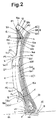
- a side rubber V is disposed axially outside the carcass 7.
- the side rubber layer V comprises a radially outer black sidewall rubber 15, a radially inner black sidewall rubber 16 and a middle white sidewall rubber 14 therebetween.
- a wing rubber layer 12 is interposed between the tread rubber 2 and the side rubber layer V.
- the surface of the wing rubber layer 12 consists of:
- the surface of the radially outer black sidewall rubber 15 consists of:
- the radially outer black sidewall rubber 15 has a substantially triangular cross sectional shape.
- the surface of the radially inner black sidewall rubber 16 consists of:
- the white sidewall rubber 14 extends from the abovementioned point (b) to the point (d). In the range from the point (c) to the point (d), the axially inner surface 14a of the white sidewall rubber 14 abuts on the outer surface of the carcass 7. A part 14b of the surface from the point (c) to the point P2 abuts on the surface part 12c of the wing rubber layer 12.
- the black sidewall rubber 15, 16 is a rubber compound containing at least one kind of polymer whose principal chain has no double bond such as chlorobutyl, EPDM and the like.
- the total content of at least one kind of polymer is in a range of from 35 to 75, preferably 40 to 60 parts by weight with respect to 100 parts by weight of the rubber polymer (for example, 100 parts by weight of the rubber polymer is 25 parts by weight of chlorobutyl and 25 parts by weight of EPDM and 50 parts by weight of natural rubber NR).
- An antidegradant which causes an unfavourable colour change to the white rubber layer 14 is not used.
- the antidegradant includes antiozonant, antioxidant, wax and the like, and a widely used antiozonant includes amine which causes colour change. Therefore, such antiozonant is not used.
- the wing rubber layer 12 is interposed between the side rubber V and tread rubber 2 to secure the connection therebetween, the wing rubber layer 12 is made of a rubber compound which has a good bonding property with the tread rubber 10, radially outer black sidewall rubber 15, white rubber layer 14 and the topping rubber of the carcass 7. As the wing rubber layer 12 does not appear on the tyre outer surface, it is not always necessary to add an antiozonant, but it is also possible to add one.
- the radial height of the point (d) at which the radially inner end of the white sidewall rubber 14 is disposed is set in a range of from 50 to 150 %, preferably 70 to 130 % (in this embodiment not more than 100%) of the height of the flange of the wheel rim.
- a radial height is measured from the bead base line BL under a standard condition in which the tyre is mounted on the standard rim and inflated to the standard load.
- the thickness measured normally to the axially outer surface 15c becomes a maximum at the above-mentioned point P2, and the maximum thickness DS is set in a range of not less than 3 mm, preferably 3.5 to 4.5 mm, more preferably 4.0 to 4.5 mm. From the point P2, the thickness gradually decreases towards the radially outer end and inner end at P1 and P3, respectively. As a result, the radially outer black sidewall rubber 15 has a substantially triangular cross sectional shape.
- the radially outer end portion of the white sidewall rubber 14 is tapered towards the point P2.
- the white rubber layer 14 appears on the outside of the tyre and protrudes axially outwards of the tyre.
- the protruding portion 17 increases the thickness DP of the white rubber layer 14 to increase the sidewall rigidity.
- the surface of the protruding portion 17 consists of:
- the convex part 14c3 is substantially parallel to a curved line drawn tangentially to the part 15c at point P3 and further tangentially to the part 16b1 at point P4.
- the thickness DP measured from the surface 14c3 to the cords of the carcass 7 normally to the surface 14c3 is set in the range of not less than 4 mm, preferably 4.5 to 5.5 mm, more preferably 5.0 to 5.5 mm. Further, the radial distance between the points P3 and P4 is preferably in a range of not more than 35 mm.
- the protruding portion 17 in this embodiment extends continuously in the tyre circumferential direction. But, it is also possible to break the protruding portion 17 regularly or irregularly in the tyre circumferential direction as far as the rotational balance of the tyre is maintained. Of course, letters, marks and the like can be provided on the surface of the white sidewall rubber 14.
- the thickness DP of the white rubber 14 is increased in the protruding portion 17, change of colour by the antidegradant of the topping rubber of the carcass 7 can be prevented. Further, the rigidity is appropriately increased to improve the steering stability and durability.
- the radially outer ends of the turnup portions of the carcass plies 6A, 6B and 6C are disposed at different radial heights.
- the heights are gradually decreased from the axially outmost turnup portion to the axially innermost turnup portion.
- the radial heights are gradually decreased in the following order: the end 6A1 of the turnup portion of the inner ply 6A; the end 6B2 of the turnup portion of the middle ply 6B; and the end 6C1 of the turnup portion of the outer ply 6C.
- the ends 6A1, 6B1 and 6C1 of all the turnup portions are disposed in a radial height range between the points P5 and P6, whereby the rigidity in the protruding portion 17 is further improved, and so called cord-grooving -- a circumferentially extending dent caused on the tyre outer surface along the edge of the turnup portion -- is effectively prevented.
- Each bead portion 4 is provided with a reinforcing layer 23 made of organic fibre cords extending between the bead toe 20 and the bead heel 21 and extending radially outwards from the bead toe 20 and bead heel 21.
- the axially outer edge of the reinforcing layer 23 reaches to the radially inner end (point d) of the white sidewall rubber 14 and is disposed between the radially inner black sidewall rubber 16 and the carcass 6.
- the axially inner edge of the reinforcing layer 23 is also extended to the almost same radial height as the outer edge.
- the radially inner black sidewall rubber 16 and the radially outer black sidewall rubber 15 are the same rubber compound, but it is possible to increase the hardness of the radially inner black sidewall rubber 16 to improve the resistance to rim chafing.
- Test tyre of size 150/90-15 having the same structure shown in Figs.1 and 2 except for the thickness DP of the white rubber layer and rubber compounds for the black sidewall rubbers were made.
- the carcass was composed of three plies of nylon fibre cords arranged at 30 degrees with respect to the tyre equator .
- the carcass ply turnup portions' heights were 60, 50 and 40 mm (from the axially outside to the inside).
- the belt was composed of two plies of nylon fibre cords laid at 30 degrees with respect to the tyre equator.
- the test tyres mounted on a standard wheel rim of size 15XMT4.00 and inflated to an inner pressure of 280 kPa were tested as follows.
- a Japanese motorcycle having a 1200cc 4-cycle engine provided on the rear wheel with a test tyre was run on a dry asphalt road in a test course, and the handling stability was evaluated by the test rider into five ranks. The higher the rank, the better the handling stability.
- test tyre was run for 200 hours at a speed of 65 km/h under a tyre load of 419 kgf at a room temperature of 25 deg. C, and the outside of the tyre was checked and then the inside was checked by a cut-open inspection.
- the white sidewall rubber extends between a position near the tread edge to the bead portion so as to form the major part of the tyre sidewall.
- the thin part of the radially outer black sidewall rubber on the axially outside of the white sidewall rubber which extends from the point P3 towards the point P2 functions as a veneer rubber, and the thick part axially outside the point P2 has a function to secure the radially outer end of the white rubber deep in the tyre sidewall.
- the wing rubber has a function to improve the bond between the white rubber and the tread rubber in co-operation with the radially outer black rubber.
- the radially inner black sidewall rubber has functions to protect the white rubber from the rim flange and to reinforce and veneer the radially inner part thereof.
- the white rubber is disposed on the axially outside of the carcass instead of the usual black sidewall rubber and the radially outer and inner black sidewall rubber is used for the above explained supplemental purposes.
- the present invention is suitably applied to a motorcycle tyre of which aspect ratio is not less than 70% independently of a carcass structure - bias or radial - and belted or not.
- a motorcycle tyre of which aspect ratio is not less than 70% independently of a carcass structure - bias or radial - and belted or not.
- other vehicle tyres such as passenger car tyres.
Landscapes
- Engineering & Computer Science (AREA)
- Mechanical Engineering (AREA)
- Tires In General (AREA)
- Compositions Of Macromolecular Compounds (AREA)
Abstract
Description

Claims (7)
- A pneumatic tyre comprising a tread rubber layer (2) disposed radially outside a carcass (6) to define a part of the tyre outer surface between tread edges (P1), a side rubber layer (V) disposed axially outside the carcass (6) to define a part of the tyre outer surface radially inward of each said tread edge (P1), characterised in that said side rubber layer (V) comprises a radially outer black sidewall rubber (15), a radially inner black sidewall rubber (16) and a white sidewall rubber (14) therebetween, a wing rubber layer (12) interposed between the tread rubber layer (2) and the side rubber layer (V), the surface of said wing rubber layer (12) consisting of a part (12a) contacting with the carcass (6), a part (12b) contacting with the tread rubber layer (2), and a part (12c) contacting with the radially outer black sidewall rubber (15) and the white sidewall rubber (14), and the surface of the radially outer black sidewall rubber (15) consisting of a part (15c) extending form the tread edge (P1) to a point (P3) on the tyre outer surface, a part (15a) contacting with the wing rubber layer (12) and extending from the tread edge (P1) to a point (P2), and a part (15b) contacting with the white sidewall rubber (14) and extending from the point (P2) to the point (P3), the radially inner black sidewall rubber (16) extending radially inwardly from a point (P4) on the tyre outer surface radially inside said point (P3) while contacting with the axially outside of the white sidewall rubber (14), the white sidewall rubber (14) provided between the point (P3) and the point (P4) with a protruding part (17) so that the thickness (DP) of the white sidewall rubber (14) in the protruding part (17) measured from the outer surface to cords of the carcass is not less than 4 mm, and the thickness (DS) of the radially outer black sidewall rubber (15) having a maximum value of not less than 3 mm at the point (P2).
- A pneumatic tyre as set forth in claim 1, characterised in that each of the radially outer black sidewall rubber (15) and radially inner black sidewall rubber (16) contains a polymer whose main chain has no double bond.
- A pneumatic tyre as set forth in claim 1 or 2, characterised in that the carcass (6) comprises three plies which are turned up in each bead portion (4) from the inside to the outside of the tyre to form three turnup portions (6a,6b,6c), the radially outer ends (6A1,6B1,6C1) of which are disposed axially inside said protruding part (17), and the radial heights of the radially outer ends are gradually decreased from the axially outer turnup portion (6a) to the axially inner turnup portion (6c).
- A pneumatic tyre according to any of claims 1 to 3, characterised in that the thickness (DP) of the white sidewall rubber is in the range of 4.5 to 5.5 mm.
- A pneumatic tyre according to any of claims 1 to 3, characterised in that the thickness (DP) of the white sidewall rubber is in the range of 5.0 to 5.5 mm.
- A pneumatic tyre according to any of claims 1 to 5 characterised in that the thickness (DS) is in the range of 3.5 to 4.5 mm.
- A pneumatic tyre according to any of claims 1 to 5 characterised in that the thickness (DS) is in the range of 4.0 to 4.5 mm.
Applications Claiming Priority (2)
| Application Number | Priority Date | Filing Date | Title |
|---|---|---|---|
| JP14837099A JP3382179B2 (en) | 1999-05-27 | 1999-05-27 | Pneumatic tire |
| JP14837099 | 1999-05-27 |
Publications (4)
| Publication Number | Publication Date |
|---|---|
| EP1057662A2 true EP1057662A2 (en) | 2000-12-06 |
| EP1057662A8 EP1057662A8 (en) | 2001-03-28 |
| EP1057662A3 EP1057662A3 (en) | 2001-11-21 |
| EP1057662B1 EP1057662B1 (en) | 2005-11-02 |
Family
ID=15451251
Family Applications (1)
| Application Number | Title | Priority Date | Filing Date |
|---|---|---|---|
| EP00304682A Expired - Lifetime EP1057662B1 (en) | 1999-05-27 | 2000-05-26 | Pneumatic tyre |
Country Status (4)
| Country | Link |
|---|---|
| US (1) | US6619355B1 (en) |
| EP (1) | EP1057662B1 (en) |
| JP (1) | JP3382179B2 (en) |
| DE (1) | DE60023593T2 (en) |
Cited By (2)
| Publication number | Priority date | Publication date | Assignee | Title |
|---|---|---|---|---|
| EP2261062A1 (en) * | 2009-06-11 | 2010-12-15 | Sumitomo Rubber Industries, Ltd. | Motorcycle tire |
| EP2602125A1 (en) * | 2011-12-05 | 2013-06-12 | Sumitomo Rubber Industries Limited | Pneumatic tire |
Families Citing this family (14)
| Publication number | Priority date | Publication date | Assignee | Title |
|---|---|---|---|---|
| WO2006049222A1 (en) | 2004-11-04 | 2006-05-11 | Bridgestone Corporation | Tire production method |
| JP4328368B2 (en) * | 2007-06-07 | 2009-09-09 | 株式会社ブリヂストン | Pneumatic tires for motorcycles |
| JP4383466B2 (en) * | 2007-06-13 | 2009-12-16 | 株式会社ブリヂストン | Pneumatic tires for motorcycles |
| JP4328371B2 (en) * | 2007-07-24 | 2009-09-09 | 株式会社ブリヂストン | Pneumatic tires for motorcycles |
| JP4723659B2 (en) * | 2009-02-24 | 2011-07-13 | 住友ゴム工業株式会社 | Pneumatic tires for motorcycles |
| JP5809909B2 (en) * | 2011-09-29 | 2015-11-11 | 東洋ゴム工業株式会社 | Pneumatic tire |
| FR3045496B1 (en) * | 2015-12-19 | 2017-12-08 | Michelin & Cie | TIRE WITH RADIAL OR CROSSED CARCASS WITH LARGE DIAMETER CABLES |
| JP7243131B2 (en) * | 2018-10-31 | 2023-03-22 | 住友ゴム工業株式会社 | pneumatic tire |
| JP7472526B2 (en) * | 2020-02-19 | 2024-04-23 | 住友ゴム工業株式会社 | Bias tires for motorcycles |
| JP7472527B2 (en) * | 2020-02-19 | 2024-04-23 | 住友ゴム工業株式会社 | Bias tires for motorcycles |
| JP7654950B2 (en) * | 2020-10-02 | 2025-04-02 | 住友ゴム工業株式会社 | Pneumatic tires |
| CN113895068B (en) * | 2021-11-08 | 2024-09-03 | 山东兴鸿源轮胎有限公司 | White rubber composite tread of low-section white-character and white-ring tire, pre-mouth shape and application thereof |
| JP7850792B1 (en) * | 2024-12-26 | 2026-04-23 | Toyo Tire株式会社 | pneumatic tires |
| JP7850793B1 (en) * | 2024-12-26 | 2026-04-23 | Toyo Tire株式会社 | pneumatic tires |
Family Cites Families (8)
| Publication number | Priority date | Publication date | Assignee | Title |
|---|---|---|---|---|
| GB1017464A (en) | 1961-12-28 | 1966-01-19 | Dunlop Rubber Co | Improvements in or relating to pneumatic tyres and to methods of their manufacture |
| US3937862A (en) * | 1971-06-02 | 1976-02-10 | Compagnie Generale Des Establissements Michelin, Raison Sociale Michelin & Cie | Pneumatic tires |
| US3830274A (en) | 1972-05-11 | 1974-08-20 | Goodyear Tire & Rubber | Elastomer blends and tire sidewalls prepared therefrom |
| JPS54142701A (en) * | 1978-04-24 | 1979-11-07 | Toyo Tire & Rubber Co Ltd | Improved radial tyre |
| JPS55164509A (en) * | 1979-06-08 | 1980-12-22 | Toyo Tire & Rubber Co Ltd | Shoulder reinforced radial tyre |
| JPS5718502A (en) * | 1980-07-04 | 1982-01-30 | Yokohama Rubber Co Ltd:The | Pneumatic tire |
| JPS60128006A (en) * | 1983-12-15 | 1985-07-08 | Sumitomo Rubber Ind Ltd | Radial tyre with improved side part |
| JP2906054B2 (en) * | 1987-12-28 | 1999-06-14 | 横浜ゴム株式会社 | Pneumatic tire |
-
1999
- 1999-05-27 JP JP14837099A patent/JP3382179B2/en not_active Expired - Fee Related
-
2000
- 2000-05-26 US US09/578,689 patent/US6619355B1/en not_active Expired - Lifetime
- 2000-05-26 EP EP00304682A patent/EP1057662B1/en not_active Expired - Lifetime
- 2000-05-26 DE DE60023593T patent/DE60023593T2/en not_active Expired - Lifetime
Cited By (2)
| Publication number | Priority date | Publication date | Assignee | Title |
|---|---|---|---|---|
| EP2261062A1 (en) * | 2009-06-11 | 2010-12-15 | Sumitomo Rubber Industries, Ltd. | Motorcycle tire |
| EP2602125A1 (en) * | 2011-12-05 | 2013-06-12 | Sumitomo Rubber Industries Limited | Pneumatic tire |
Also Published As
| Publication number | Publication date |
|---|---|
| EP1057662A3 (en) | 2001-11-21 |
| US6619355B1 (en) | 2003-09-16 |
| EP1057662B1 (en) | 2005-11-02 |
| DE60023593D1 (en) | 2005-12-08 |
| JP2000335212A (en) | 2000-12-05 |
| EP1057662A8 (en) | 2001-03-28 |
| JP3382179B2 (en) | 2003-03-04 |
| DE60023593T2 (en) | 2006-07-20 |
Similar Documents
| Publication | Publication Date | Title |
|---|---|---|
| EP1057662B1 (en) | Pneumatic tyre | |
| US7308924B2 (en) | Pneumatic radial tire | |
| US7036541B2 (en) | Pneumatic tire | |
| EP2206612B1 (en) | Tire for motor-bicycle | |
| EP3666556B1 (en) | Pneumatic tyre | |
| WO1997007996A1 (en) | Low aspect ratio truck tire | |
| US6742559B2 (en) | Pneumatic tire including wing rubber | |
| CA1321537C (en) | Pneumatic radial tire | |
| US6719026B2 (en) | Pneumatic tire having tread including pair of axially outer base rubber layers | |
| US7712498B2 (en) | Run flat tire | |
| EP0410673B1 (en) | A Radial tyre for heavy duty vehicles | |
| US6752186B1 (en) | Pneumatic tire | |
| EP0881102B1 (en) | Heavy duty pneumatic tyre | |
| EP0435620B1 (en) | A radial tyre for a passenger car | |
| CA1213201A (en) | Pneumatic tire | |
| US20190263183A1 (en) | Two-wheeled vehicle tyre | |
| EP0596737B1 (en) | Radial tyre | |
| JPH11342709A (en) | Radial tire | |
| EP0361871B1 (en) | A radial tyre for motor cycle | |
| US20220219497A1 (en) | Pneumatic tire | |
| US6167932B1 (en) | Pneumatic tire for passenger cars having specified harshness factor | |
| JPH03169719A (en) | Pneumatic tire | |
| EP0835768B1 (en) | Pneumatic tyres | |
| EP1074404B1 (en) | Pneumatic tire for passenger cars | |
| JPH09109619A (en) | Pneumatic radial tire |
Legal Events
| Date | Code | Title | Description |
|---|---|---|---|
| PUAI | Public reference made under article 153(3) epc to a published international application that has entered the european phase |
Free format text: ORIGINAL CODE: 0009012 |
|
| AK | Designated contracting states |
Kind code of ref document: A2 Designated state(s): AT BE CH CY DE DK ES FI FR GB GR IE IT LI LU MC NL PT SE Kind code of ref document: A2 Designated state(s): DE FR GB |
|
| AX | Request for extension of the european patent |
Free format text: AL;LT;LV;MK;RO;SI |
|
| RAP1 | Party data changed (applicant data changed or rights of an application transferred) |
Owner name: SUMITOMO RUBBER INDUSTRIES LIMITED |
|
| PUAL | Search report despatched |
Free format text: ORIGINAL CODE: 0009013 |
|
| AX | Request for extension of the european patent |
Free format text: AL;LT;LV;MK;RO;SI |
|
| 17P | Request for examination filed |
Effective date: 20020429 |
|
| AKX | Designation fees paid |
Free format text: DE FR GB |
|
| GRAP | Despatch of communication of intention to grant a patent |
Free format text: ORIGINAL CODE: EPIDOSNIGR1 |
|
| GRAS | Grant fee paid |
Free format text: ORIGINAL CODE: EPIDOSNIGR3 |
|
| GRAA | (expected) grant |
Free format text: ORIGINAL CODE: 0009210 |
|
| RAP1 | Party data changed (applicant data changed or rights of an application transferred) |
Owner name: SUMITOMO RUBBER INDUSTRIES LIMITED |
|
| AK | Designated contracting states |
Kind code of ref document: B1 Designated state(s): DE FR GB |
|
| REG | Reference to a national code |
Ref country code: GB Ref legal event code: FG4D |
|
| REF | Corresponds to: |
Ref document number: 60023593 Country of ref document: DE Date of ref document: 20051208 Kind code of ref document: P |
|
| ET | Fr: translation filed | ||
| PLBE | No opposition filed within time limit |
Free format text: ORIGINAL CODE: 0009261 |
|
| STAA | Information on the status of an ep patent application or granted ep patent |
Free format text: STATUS: NO OPPOSITION FILED WITHIN TIME LIMIT |
|
| 26N | No opposition filed |
Effective date: 20060803 |
|
| PGFP | Annual fee paid to national office [announced via postgrant information from national office to epo] |
Ref country code: GB Payment date: 20140521 Year of fee payment: 15 |
|
| PGFP | Annual fee paid to national office [announced via postgrant information from national office to epo] |
Ref country code: DE Payment date: 20140521 Year of fee payment: 15 Ref country code: FR Payment date: 20140509 Year of fee payment: 15 |
|
| REG | Reference to a national code |
Ref country code: DE Ref legal event code: R119 Ref document number: 60023593 Country of ref document: DE |
|
| GBPC | Gb: european patent ceased through non-payment of renewal fee |
Effective date: 20150526 |
|
| REG | Reference to a national code |
Ref country code: FR Ref legal event code: ST Effective date: 20160129 |
|
| PG25 | Lapsed in a contracting state [announced via postgrant information from national office to epo] |
Ref country code: DE Free format text: LAPSE BECAUSE OF NON-PAYMENT OF DUE FEES Effective date: 20151201 Ref country code: GB Free format text: LAPSE BECAUSE OF NON-PAYMENT OF DUE FEES Effective date: 20150526 |
|
| PG25 | Lapsed in a contracting state [announced via postgrant information from national office to epo] |
Ref country code: FR Free format text: LAPSE BECAUSE OF NON-PAYMENT OF DUE FEES Effective date: 20150601 |