EP1057627A2 - Printing and coating machines - Google Patents
Printing and coating machines Download PDFInfo
- Publication number
- EP1057627A2 EP1057627A2 EP00304715A EP00304715A EP1057627A2 EP 1057627 A2 EP1057627 A2 EP 1057627A2 EP 00304715 A EP00304715 A EP 00304715A EP 00304715 A EP00304715 A EP 00304715A EP 1057627 A2 EP1057627 A2 EP 1057627A2
- Authority
- EP
- European Patent Office
- Prior art keywords
- cylinder
- blanket
- leading edge
- recesses
- Prior art date
- Legal status (The legal status is an assumption and is not a legal conclusion. Google has not performed a legal analysis and makes no representation as to the accuracy of the status listed.)
- Withdrawn
Links
Images


Classifications
-
- B—PERFORMING OPERATIONS; TRANSPORTING
- B41—PRINTING; LINING MACHINES; TYPEWRITERS; STAMPS
- B41F—PRINTING MACHINES OR PRESSES
- B41F21/00—Devices for conveying sheets through printing apparatus or machines
- B41F21/12—Adjusting leading edges, e.g. front stops
-
- B—PERFORMING OPERATIONS; TRANSPORTING
- B41—PRINTING; LINING MACHINES; TYPEWRITERS; STAMPS
- B41F—PRINTING MACHINES OR PRESSES
- B41F21/00—Devices for conveying sheets through printing apparatus or machines
- B41F21/10—Combinations of transfer drums and grippers
Definitions
- This invention relates to printing and coating machines which apply printing ink or coatings to sheet material or substrates and, more particularly but not exclusively, to offset litho printing presses in which print is transferred from a blanket on a blanket cylinder to a sheet of metal supported on an impression cylinder.
- each sheet to be printed is pushed by a conveyor into the pass gap between the blanket cylinder and the impression cylinder until it abuts a stop or register lay on the impression cylinder, whereon grippers mounted on the impression cylinder grip the leading edge of the sheet.
- the stop or register lay is located so that the edge of the stopped sheet is ahead of the print on the blanket by a margin adequate for the grippers to act on.
- the leading edge of the blanket cylinder is set back from the register lay and gripper mechanisms on the support or impression cylinder to avoid contact, resulting in the leading edge of the blanket which carries the image to be printed, falling some way short of the gripping mechanism and the leading cut edge of the sheet and hence being unable to transfer the images to the leading edge margin of the flat sheet which is being held by the gripping mechanisms.
- This invention seeks to permit the printing of the image down to the leading cut edge except where the registration and gripping mechanisms intrude. Normally, the invention will be used with images which will accommodate the intruding mechanisms, such as staggered arrays of printed cap blanks or coated lids where the intrusions or missing image are not critical.
- this invention provides a printing machine having a print cylinder to convey print or coating to a sheet material, an impression support in the form of an impression cylinder or an impression block to support the sheet material, means to stop the leading edge of the sheet material in register with the print or coating on the print cylinder, and means to grip the sheet material as it passes between the print cylinder and impression support, characterised in that recesses are provided in the leading edge of the print cylinder to accommodate the stop means and the gripper means as the cylinder rotates relative to the impression support.
- the impression support may be a cylinder (when a rotary press is used) or a flat bed.
- the print cylinder has, at one point of its circumference, a leading edge where the first part of the image to be printed is located on the cylinder.
- the recesses may be formed directly in the material of the print cylinder, at the leading edge, or alternatively may be formed in an insert or inserts which can be fixed in suitable sockets in the cylinder.
- Printing can be carried out with or without a blanket.
- Inserts of appropriate shape permit change of the register lay and gripper positions to fit the array to be printed.
- the print cylinder is in the form of a cylinder around which is fixed a printing blanket
- the support means is in the form of an impression cylinder
- the stop means or register lay is mounted on the impression cylinder to stop the leading edge of the sheet material in line with the start of the print or coating on the blanket.
- the blanket follows the contours of the recesses and the stop means/register lay and grippers on the impression cylinder enter the recessed profiles on the leading edge of the blanket where the blanket overlies the recesses.
- the printing blanket may be to a degree flexible and under tension may be deformed to adopt the shape of the profiled leading edge of the blanket cylinder.
- Offset litho printing blankets are usually held under tension on their cylinders. Blankets under tension on their cylinders may be induced to adopt the shape of the recesses in the profiled leading edges with selectively placed cuts into or through the blanket material.
- adhesive backed blankets eliminate the need for the tension and are cut according to the leading edge of the blanket cylinder and the recesses.
- this invention provides a method of operating a printing machine comprising the steps of:
- a printing blanket is stretched around the printing cylinder to drape the blanket into the profiled recesses, the impression support is an impression cylinder and the stop means and gripper means are mounted on the impression cylinder.
- the blanket may be chosen to have thickness and resilience to accommodate the stop means and gripper means passing under it.
- a typical thickness is about 1.9 mm.
- Blankets are conventionally constructed of a rubber face layer supported on a woven backing layer.
- the cylinders shown in these drawings are suitable for use in an offset litho press used for printing an array of blanks on sheet metal, such as tinplate or aluminium as used on drawn articles including caps, lids and can ends.
- sheet metal such as tinplate or aluminium as used on drawn articles including caps, lids and can ends.
- Each sheet of metal brought by a conveyor is pushed in between the contra-rotating blanket cylinder and impression cylinder to abut a stop which registers it with decoration on the blanket.
- the leading edge of the sheet is gripped before printing while the cylinders continue to rotate.
- inking rolls transfer ink from a reservoir to a printing plate on a printing cylinder.
- the printing plate transfers an inked image to the blanket on the blanket cylinder, which in turn applies the image onto the metal.
- This description is limited to the blanket cylinder, the impression cylinder and the decorative layout of the sheet as the remainder of the printing apparatus will be familiar to those skilled in the art.
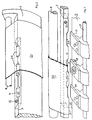
- Figure 1 shows a blanket cylinder 1 and an impression cylinder 2 which, when in use, are supported for contra-rotation in bearings which hold the cylinders apart at a distance substantially equal to the thickness (m) of a sheet (shown by dashed lines) to be printed.
- Each cylinder has a drive gear 3 and when the gears 3 are meshed together they ensure synchronised rotation of the cylinders.
- the cylinder surface of the blanket cylinder 1 has a cavity 4 extending the length of the cylinder from a gear side flange 5 to an opposite flange 6.
- a pair of blanket tensioner rods 7, 8 are supported between flanges 5 and 6 to span the length of the cavity 4. This much is conventional.
- the blanket cylinder 1 has gaps or sockets 10 in a front or leading edge 9, into each of which is fixed a profiled insert 11.
- the insert 11 is shown on an enlarged scale in Figure la, to show details of three recesses 20, 21 and 22 in the leading edge of the insert. When the insert is in place (held by socket head screws 12) the leading edge of the insert is aligned with the leading edge of the cavity 4.
- the cylindrical wall of the impression cylinder has a cavity 14 extending from an end flange 15 near gear 3 to an opposite end flange 16.
- a rod 17 extends between the gear-side flange 15 and the other flange 16 to support stop means or register lays 18 and sheet grippers 19.
- the recesses 20 and 22 in the insert 11 are of a size to accommodate the grippers 19 as the cylinders rotate, while recess 21 is of a size to accommodate the register lay 18.
- Figure 2 shows one side of the front edge of the blanket cylinder 1 with part of a blanket 23.
- the blanket is stretched by a tensioner 8 so that it is deflected into the recesses 20, 21, 22 in the blanket cylinder insert 11, as indicated at 24.
- Figure 3 shows the front edge 9 of the blanket cylinder 1 and the front edge 25 of impression cylinder 2 near their meeting point, with the grippers 19 and register tip 18 on the impression cylinder 2 about to fit into the deflected areas 24 over the recesses 20, 21 22 on the front edge 9 of the blanket cylinder 1. From this position, the front edge 25 of the impression cylinder 2 then moves to pass the front edge 9 of the blanket cylinder.
- Figure 4 shows printed images 26 extending to the front cut edge A of the sheet 27 between the grippers 19 and the register lay 18.
- each spent image 28 on the blanket 23 lies between the recesses 20, 21, 22 and the leading edge 9 of the blanket cylinder.
- Figure 5 shows a fragment of a printed sheet 27 on which the leading row of printed blanks are denoted 26, the periphery of each blank reaching substantially the edge A of the sheet.
- the prior art limit to the gripper margin is denoted B so that the areas now available, by virtue of the invention are generally denoted C. Only the areas denoted D are not now available for print or coating because space is needed for grippers 19 and register lay 18.
- register lay 18 is adjustable laterally, and grippers 19 and register lay 18 may be moved along rod 17 to fit between images in a multi-image array.
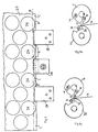
- Figure 6a shows end views of a prior art blanket cylinder 1 and impression cylinder 2.
- Figure 6b shows corresponding views of cylinders 1,2 according to the invention.
- printing does not start until the sheet m has advanced far enough for the register lay 18 and grippers 19 which operate on the leading edge of the sheet m to clear the approaching free edge 9 of the blanket cylinder.
- printing can start right at the edge of the sheet m by virtue of the relieved blanket cylinder insert at 11 which allows register lay 18 and grippers 19 to pass under the blanket cylinder 1, with the front edge 25 of the recess in the impression cylinder 2 being substantially in line with the leading edge 9 of the blanket cylinder at the start of printing.
- Figure 7 shows part of a blanket cylinder where the recesses 20, 21 or 22 are cut directly into the metal of the cylinder.
- Figure 7a shows how the blanket 23 (under tension from a tensioner 8) can have a cut or cuts 34 cut in from the front edge of the blanket to assist in the deflection (stretching) of the blanket into the respective recesses 20, 21, or 22 in the leading edge 9 of the blanket cylinder 1.
- Figure 8 shows one side of the front edge of the blanket cylinder 1 with an adhesive backed blanket 23. This needs no tension from a tensioner 8, so the blanket is not deflected into recesses 20, 21, 22 in the blanket cylinder. Instead the blanket is shaped along the front edge 9 to conform to the profile of the recesses 20, 21, 22 of the insert 11. Numeral 33 indicates the adhesive layer on the underside of the blanket 23.
- Figure 9 shows the front edge 9 of the blanket cylinder 1 and the front edge 25 of impression cylinder 2 near the meeting point with the grippers 19 and register tip 18 on the impression cylinder about to fit into the recesses 20, 21, 22 on the front edge 9 of the blanket cylinder 1 as the front edge 25 of the impression cylinder passes the front edge 9 of the blanket cylinder.
- 23 shows the adhesive blanket cut to the profile of the front edge 9 of blanket cylinder 1 and cut to the profiles of the recesses 20 and 21.
- the blanket is prepared with a cut leading edge placed substantially in line with the leading edge of the blanket cylinder 9.
- Recesses are cut into the leading edge of the blanket substantially in line with the recesses in the blanket cylinder.
- this invention permits printing or coating of a sheet right up to its leading edge in a single printing pass, so avoiding the expense of an extra step, such as rotating through 180 degrees and printing a second pass to complete the printed array; or an ink jet spray; or a tampo type dab; as would otherwise be needed to complete the array.
Abstract
Description
- This invention relates to printing and coating machines which apply printing ink or coatings to sheet material or substrates and, more particularly but not exclusively, to offset litho printing presses in which print is transferred from a blanket on a blanket cylinder to a sheet of metal supported on an impression cylinder.
- In known printing presses, such as US Patents 4,475,459 and 5,473,983, each sheet to be printed is pushed by a conveyor into the pass gap between the blanket cylinder and the impression cylinder until it abuts a stop or register lay on the impression cylinder, whereon grippers mounted on the impression cylinder grip the leading edge of the sheet. The stop or register lay is located so that the edge of the stopped sheet is ahead of the print on the blanket by a margin adequate for the grippers to act on.
- This existing mechanical limitation results from the fact that sheet-fed presses have to register and hold the leading or front edge with registering and gripping mechanisms placed on the impression cylinder. These must be positioned in such a way that there is no interference or contact with this gripping mechanism and any other parts of the machine, particularly the image carrier or blanket cylinder and its covering.
- The result is that, with current methods, the leading edge of the blanket cylinder is set back from the register lay and gripper mechanisms on the support or impression cylinder to avoid contact, resulting in the leading edge of the blanket which carries the image to be printed, falling some way short of the gripping mechanism and the leading cut edge of the sheet and hence being unable to transfer the images to the leading edge margin of the flat sheet which is being held by the gripping mechanisms.
- This mechanical limitation of the prior art results in an unprinted area all along the leading or edge or front cut edge of the sheet extending inwards to an extent determined by the limitations of the individual machine. This is usually a minimum of two to three millimetres.
- This invention seeks to permit the printing of the image down to the leading cut edge except where the registration and gripping mechanisms intrude. Normally, the invention will be used with images which will accommodate the intruding mechanisms, such as staggered arrays of printed cap blanks or coated lids where the intrusions or missing image are not critical.
- Accordingly, in a first aspect, this invention provides a printing machine having a print cylinder to convey print or coating to a sheet material, an impression support in the form of an impression cylinder or an impression block to support the sheet material, means to stop the leading edge of the sheet material in register with the print or coating on the print cylinder, and means to grip the sheet material as it passes between the print cylinder and impression support, characterised in that recesses are provided in the leading edge of the print cylinder to accommodate the stop means and the gripper means as the cylinder rotates relative to the impression support.
- The impression support may be a cylinder (when a rotary press is used) or a flat bed.
- The print cylinder has, at one point of its circumference, a leading edge where the first part of the image to be printed is located on the cylinder. The recesses may be formed directly in the material of the print cylinder, at the leading edge, or alternatively may be formed in an insert or inserts which can be fixed in suitable sockets in the cylinder.
- Printing can be carried out with or without a blanket.
- Inserts of appropriate shape permit change of the register lay and gripper positions to fit the array to be printed.
- In one embodiment the print cylinder is in the form of a cylinder around which is fixed a printing blanket, the support means is in the form of an impression cylinder and the stop means or register lay is mounted on the impression cylinder to stop the leading edge of the sheet material in line with the start of the print or coating on the blanket. In use, the blanket follows the contours of the recesses and the stop means/register lay and grippers on the impression cylinder enter the recessed profiles on the leading edge of the blanket where the blanket overlies the recesses.
- The printing blanket may be to a degree flexible and under tension may be deformed to adopt the shape of the profiled leading edge of the blanket cylinder. Offset litho printing blankets are usually held under tension on their cylinders. Blankets under tension on their cylinders may be induced to adopt the shape of the recesses in the profiled leading edges with selectively placed cuts into or through the blanket material. Alternatively adhesive backed blankets eliminate the need for the tension and are cut according to the leading edge of the blanket cylinder and the recesses.
- In a second aspect, this invention provides a method of operating a printing machine comprising the steps of:
- passing a sheet of material between a print cylinder, carrying an array of print images or coating images, and an impression support;
- abutting the leading edge of the sheet against stop means on the support means to be in register with the print or coating images on the print cylinder;
- applying gripping means to the leading edge of the sheet between images; and
- during start of printing or coating, passing the gripping and stop means into concave recesses in a leading edge of the surface of the print cylinder.
-
- In a preferred method, a printing blanket is stretched around the printing cylinder to drape the blanket into the profiled recesses, the impression support is an impression cylinder and the stop means and gripper means are mounted on the impression cylinder.
- The blanket may be chosen to have thickness and resilience to accommodate the stop means and gripper means passing under it. A typical thickness is about 1.9 mm. Blankets are conventionally constructed of a rubber face layer supported on a woven backing layer.
- Various embodiments will now be described by way of example and with reference to the accompanying drawings in which:
- Figure 1 is a perspective sketch showing a continuously rotatable blanket cylinder and an impression cylinder;
- Figure 1a is a perspective sketch of a profiled insert on an enlarged scale;
- Figure 2 is a perspective sketch of a fragment of the blanket cylinder of Figure 1 with insert and blanket under tension;
- Figure 3 is a perspective sketch of a fragment of the blanket cylinder as shown in Figure 2. with the blanket under tension and impression cylinder showing gripper and register tips;
- Figure 4 is a perspective sketch showing print location on the blanket after application to the sheet;
- Figure 5 is a plan view of the sheet showing the prior art limit to gripper margin and improved use of sheet;
- Figures 6a and 6b are sectional views showing, respectively, a prior art configuration and a configuration according to the present invention;
- Figure 7 is a perspective sketch of an alternative form of blanket cylinder;
- Figure 7a shows a part of the cylinder of Figure 7 on a larger scale;
- Figure 8 is a perspective sketch of a fragment of the blanket cylinder of Figure 1 with an adhesive backed blanket; and
- Figure 9 is a perspective sketch of a fragment of blanket cylinder as shown in Figure 7 together with an impression cylinder showing gripper and register tips.
-
- The cylinders shown in these drawings are suitable for use in an offset litho press used for printing an array of blanks on sheet metal, such as tinplate or aluminium as used on drawn articles including caps, lids and can ends. Each sheet of metal brought by a conveyor is pushed in between the contra-rotating blanket cylinder and impression cylinder to abut a stop which registers it with decoration on the blanket. The leading edge of the sheet is gripped before printing while the cylinders continue to rotate.
- Typically, in such metal decorating presses, inking rolls transfer ink from a reservoir to a printing plate on a printing cylinder. The printing plate transfers an inked image to the blanket on the blanket cylinder, which in turn applies the image onto the metal. This description is limited to the blanket cylinder, the impression cylinder and the decorative layout of the sheet as the remainder of the printing apparatus will be familiar to those skilled in the art.
- Figure 1 shows a blanket cylinder 1 and an impression cylinder 2 which, when in use, are supported for contra-rotation in bearings which hold the cylinders apart at a distance substantially equal to the thickness (m) of a sheet (shown by dashed lines) to be printed. Each cylinder has a
drive gear 3 and when thegears 3 are meshed together they ensure synchronised rotation of the cylinders. - The cylinder surface of the blanket cylinder 1 has a
cavity 4 extending the length of the cylinder from agear side flange 5 to anopposite flange 6. A pair ofblanket tensioner rods flanges cavity 4. This much is conventional. - The blanket cylinder 1 has gaps or sockets 10 in a front or leading
edge 9, into each of which is fixed a profiledinsert 11. Theinsert 11 is shown on an enlarged scale in Figure la, to show details of threerecesses cavity 4. - The cylindrical wall of the impression cylinder has a
cavity 14 extending from an end flange 15 neargear 3 to anopposite end flange 16. Arod 17 extends between the gear-side flange 15 and theother flange 16 to support stop means or register lays 18 andsheet grippers 19. - The
recesses insert 11 are of a size to accommodate thegrippers 19 as the cylinders rotate, while recess 21 is of a size to accommodate theregister lay 18. - Figure 2 shows one side of the front edge of the blanket cylinder 1 with part of a
blanket 23. The blanket is stretched by atensioner 8 so that it is deflected into therecesses blanket cylinder insert 11, as indicated at 24. - Figure 3 shows the
front edge 9 of the blanket cylinder 1 and thefront edge 25 of impression cylinder 2 near their meeting point, with thegrippers 19 and registertip 18 on the impression cylinder 2 about to fit into thedeflected areas 24 over therecesses front edge 9 of the blanket cylinder 1. From this position, thefront edge 25 of the impression cylinder 2 then moves to pass thefront edge 9 of the blanket cylinder. - Figure 4 shows printed
images 26 extending to the front cut edge A of thesheet 27 between thegrippers 19 and the register lay 18. - It will be noted that the leading segment of each spent
image 28 on theblanket 23 lies between therecesses leading edge 9 of the blanket cylinder. - Figure 5 shows a fragment of a printed
sheet 27 on which the leading row of printed blanks are denoted 26, the periphery of each blank reaching substantially the edge A of the sheet. The prior art limit to the gripper margin is denoted B so that the areas now available, by virtue of the invention are generally denoted C. Only the areas denoted D are not now available for print or coating because space is needed forgrippers 19 and register lay 18. - It should be noted that the register lay 18 is adjustable laterally, and
grippers 19 and register lay 18 may be moved alongrod 17 to fit between images in a multi-image array. - Figure 6a shows end views of a prior art blanket cylinder 1 and impression cylinder 2. Figure 6b shows corresponding views of cylinders 1,2 according to the invention. In Figure 6a (prior art), printing does not start until the sheet m has advanced far enough for the register lay 18 and
grippers 19 which operate on the leading edge of the sheet m to clear the approachingfree edge 9 of the blanket cylinder. - However, according to this invention (Figure 6b), printing can start right at the edge of the sheet m by virtue of the relieved blanket cylinder insert at 11 which allows register lay 18 and
grippers 19 to pass under the blanket cylinder 1, with thefront edge 25 of the recess in the impression cylinder 2 being substantially in line with theleading edge 9 of the blanket cylinder at the start of printing. - The prior art limit to usable sheet is thus denoted by dashed line B (Figure 4) which, with cut edge A of the sheet, defines the margin required by prior practice to register and grip the sheet.
- Figure 7 shows part of a blanket cylinder where the
recesses - Figure 7a shows how the blanket 23 (under tension from a tensioner 8) can have a cut or
cuts 34 cut in from the front edge of the blanket to assist in the deflection (stretching) of the blanket into therespective recesses leading edge 9 of the blanket cylinder 1. - Figure 8 shows one side of the front edge of the blanket cylinder 1 with an adhesive backed
blanket 23. This needs no tension from atensioner 8, so the blanket is not deflected intorecesses front edge 9 to conform to the profile of therecesses insert 11.Numeral 33 indicates the adhesive layer on the underside of theblanket 23. - Figure 9 shows the
front edge 9 of the blanket cylinder 1 and thefront edge 25 of impression cylinder 2 near the meeting point with thegrippers 19 andregister tip 18 on the impression cylinder about to fit into therecesses front edge 9 of the blanket cylinder 1 as thefront edge 25 of the impression cylinder passes thefront edge 9 of the blanket cylinder. 23 shows the adhesive blanket cut to the profile of thefront edge 9 of blanket cylinder 1 and cut to the profiles of therecesses blanket cylinder 9. Recesses are cut into the leading edge of the blanket substantially in line with the recesses in the blanket cylinder. - It will be understood that this invention permits printing or coating of a sheet right up to its leading edge in a single printing pass, so avoiding the expense of an extra step, such as rotating through 180 degrees and printing a second pass to complete the printed array; or an ink jet spray; or a tampo type dab; as would otherwise be needed to complete the array.
Claims (11)
- A printing machine having a print cylinder (1) to convey print or coating to a sheet material (27), an impression support (2) in the form of an impression cylinder or an impression block to support the sheet material, means (18) to stop the leading edge of the sheet material in register with the print or coating on the print cylinder (1), and means (19) to grip the sheet material as it passes between the print cylinder (1) and impression support (2), characterised in that recesses (20, 21, 22) are provided in the leading edge of the print cylinder to accommodate the stop means (18) and the gripper means (19) as the cylinder rotates relative to the impression support.
- A printing machine according to claim 1 wherein the recesses (20, 21, 22) are in a profiled leading edge (9) of a recess in the surface of a print cylinder (1).
- A printing machine according to claim 1 or claim 2 wherein the recesses (20, 21, 22) are on an insert (11) fixed to the print cylinder (1).
- A printing machine according to any preceding claim wherein the print cylinder (1) is in the form of a blanket cylinder, the impression support is an impression cylinder (2), the stop means (18) is mounted on the impression cylinder (2) to stop the leading edge of a piece of sheet material (m) and, at start of printing, the stop means (18) and gripper means (19) on the impression cylinder (2) are arranged to enter complementary recesses (20, 21 and 22) in the leading edge of the blanket.
- A printing machine according to Claim 4 wherein a blanket is fitted to the blanket cylinder and the blanket follows the contours of the recesses (20, 21, 22).
- A printing machine according to Claim 4 or Claim 5, wherein the blanket (23) is of a thickness and resilience to deflect, under tensile force around the cylinder (1), into the recesses (20, 21, 22) provided by the profiled leading edge of the blanket cylinder.
- A printing machine according to Claim 4 or Claim 5, wherein the blanket (23) is held to the cylinder and around the cylinder by an adhesive (33) substantially without tensile force.
- A method of operating a printing machine comprising the steps of:passing a sheet (m) of material between a print cylinder (1), carrying an array of print images or coating images (26), and an impression support (2);abutting the leading edge (A) of the sheet against stop means (18) on the support means (2) to be in register with the print or coating images (28) on the print cylinder (1);applying gripping means (19) to the leading edge of the sheet between images; andduring start of printing or coating, passing the gripping and stop means into concave recesses in a leading edge of the surface of the print cylinder.
- A method according to Claim 8, wherein a printing blanket (23) is stretched around the print cylinder to drape blanket material locally into a profile on the leading edge (9) of print cylinder (1) to define the recesses.
- A method according to Claim 8, wherein a printing blanket is attached around the print cylinder (1) with adhesive (33) and is cut to follow the profile of the leading edge (25) of the print cylinder including the recesses (20, 21, 22).
- A method according to Claim 8 or Claim 9, wherein the blanket (23) material is chosen to have thickness and resilience to accommodate the stop means (18) and the gripper means (19) passing under it.
Applications Claiming Priority (2)
| Application Number | Priority Date | Filing Date | Title |
|---|---|---|---|
| GBGB9912830.8A GB9912830D0 (en) | 1999-06-03 | 1999-06-03 | Printing and coating machines |
| GB9912830 | 1999-06-03 |
Publications (2)
| Publication Number | Publication Date |
|---|---|
| EP1057627A2 true EP1057627A2 (en) | 2000-12-06 |
| EP1057627A3 EP1057627A3 (en) | 2002-05-22 |
Family
ID=10854617
Family Applications (1)
| Application Number | Title | Priority Date | Filing Date |
|---|---|---|---|
| EP00304715A Withdrawn EP1057627A3 (en) | 1999-06-03 | 2000-06-02 | Printing and coating machines |
Country Status (2)
| Country | Link |
|---|---|
| EP (1) | EP1057627A3 (en) |
| GB (1) | GB9912830D0 (en) |
Cited By (2)
| Publication number | Priority date | Publication date | Assignee | Title |
|---|---|---|---|---|
| WO2008084191A1 (en) * | 2007-01-08 | 2008-07-17 | Oft-Technology Limited | Lithographic coating |
| DE102007010481A1 (en) * | 2007-03-03 | 2008-09-04 | Koenig & Bauer Aktiengesellschaft | Sheet-fed rotary printing machine comprises a pressing rising curve with a starting line lying in the region of the printing cylinder with grippers lying on the cylinder |
Citations (1)
| Publication number | Priority date | Publication date | Assignee | Title |
|---|---|---|---|---|
| DE19647068A1 (en) * | 1996-02-09 | 1997-08-14 | Heidelberg Harris Sa | Grip system for flat products |
-
1999
- 1999-06-03 GB GBGB9912830.8A patent/GB9912830D0/en not_active Ceased
-
2000
- 2000-06-02 EP EP00304715A patent/EP1057627A3/en not_active Withdrawn
Patent Citations (1)
| Publication number | Priority date | Publication date | Assignee | Title |
|---|---|---|---|---|
| DE19647068A1 (en) * | 1996-02-09 | 1997-08-14 | Heidelberg Harris Sa | Grip system for flat products |
Cited By (3)
| Publication number | Priority date | Publication date | Assignee | Title |
|---|---|---|---|---|
| WO2008084191A1 (en) * | 2007-01-08 | 2008-07-17 | Oft-Technology Limited | Lithographic coating |
| DE102007010481A1 (en) * | 2007-03-03 | 2008-09-04 | Koenig & Bauer Aktiengesellschaft | Sheet-fed rotary printing machine comprises a pressing rising curve with a starting line lying in the region of the printing cylinder with grippers lying on the cylinder |
| DE102007010481B4 (en) | 2007-03-03 | 2018-12-20 | Koenig & Bauer Ag | Sheet- |
Also Published As
| Publication number | Publication date |
|---|---|
| EP1057627A3 (en) | 2002-05-22 |
| GB9912830D0 (en) | 1999-08-04 |
Similar Documents
| Publication | Publication Date | Title |
|---|---|---|
| JP4871120B2 (en) | Intaglio printing machine | |
| US4584939A (en) | Combined rotary printing machine | |
| JP2829099B2 (en) | Intaglio printing machine for printing bill paper | |
| US6382092B1 (en) | Printing machine with exchangeable ink application means | |
| EP1778490B1 (en) | Method for controlling a machine for processing sheet material | |
| US20160001546A1 (en) | Can decorator apparatus and method | |
| JPH09510410A (en) | Multicolor printing machine | |
| US4441423A (en) | Collect-printing unit for security printing for use in a rotary printing press | |
| EP0545862A1 (en) | Method and apparatus for printing multicolored container body blanks in a single pass | |
| SU1431667A3 (en) | Multiink sheet-fed or web-fed press | |
| JPH0639990A (en) | Intaglio press | |
| US4056056A (en) | Rotary printing press | |
| DE19704003A1 (en) | Method of printing individual identifiers e.g. bar-codes | |
| JP2008501547A (en) | Printer | |
| US4479431A (en) | Collect-printing unit for security printing for use in a rotary printing press | |
| EP1028058A1 (en) | Method and apparatus for printing a ribbon for packaging gelatin capsules | |
| US20050155503A1 (en) | Sheet-fed offset rotary printing press | |
| JP3491183B2 (en) | Multicolor printing method for curved objects | |
| EP1057627A2 (en) | Printing and coating machines | |
| DE102009042625A1 (en) | Sheet-fed offset printing machine for printing on both sides of sheets | |
| US6546862B1 (en) | Method and device for producing a multicolor print | |
| EP0275025A2 (en) | Inking device for printing apparatus | |
| JPH0241412B2 (en) | ||
| US4481878A (en) | Method of and apparatus for printing serial numbers | |
| JPH0364309B2 (en) |
Legal Events
| Date | Code | Title | Description |
|---|---|---|---|
| PUAI | Public reference made under article 153(3) epc to a published international application that has entered the european phase |
Free format text: ORIGINAL CODE: 0009012 |
|
| AK | Designated contracting states |
Kind code of ref document: A2 Designated state(s): AT BE CH CY DE DK ES FI FR GB GR IE IT LI LU MC NL PT SE |
|
| AX | Request for extension of the european patent |
Free format text: AL;LT;LV;MK;RO;SI |
|
| PUAL | Search report despatched |
Free format text: ORIGINAL CODE: 0009013 |
|
| AX | Request for extension of the european patent |
Free format text: AL;LT;LV;MK;RO;SI |
|
| 17P | Request for examination filed |
Effective date: 20021120 |
|
| AKX | Designation fees paid |
Designated state(s): AT BE CH CY DE DK ES FI FR GB GR IE IT LI LU MC NL PT SE |
|
| GRAP | Despatch of communication of intention to grant a patent |
Free format text: ORIGINAL CODE: EPIDOSNIGR1 |
|
| STAA | Information on the status of an ep patent application or granted ep patent |
Free format text: STATUS: THE APPLICATION IS DEEMED TO BE WITHDRAWN |
|
| 18D | Application deemed to be withdrawn |
Effective date: 20040330 |