EP1057566A2 - Brazing fixture for a heat exchanger. - Google Patents
Brazing fixture for a heat exchanger. Download PDFInfo
- Publication number
- EP1057566A2 EP1057566A2 EP00304222A EP00304222A EP1057566A2 EP 1057566 A2 EP1057566 A2 EP 1057566A2 EP 00304222 A EP00304222 A EP 00304222A EP 00304222 A EP00304222 A EP 00304222A EP 1057566 A2 EP1057566 A2 EP 1057566A2
- Authority
- EP
- European Patent Office
- Prior art keywords
- core
- clamp
- leg members
- contact
- bight portion
- Prior art date
- Legal status (The legal status is an assumption and is not a legal conclusion. Google has not performed a legal analysis and makes no representation as to the accuracy of the status listed.)
- Withdrawn
Links
- 238000005219 brazing Methods 0.000 title abstract description 31
- 238000004519 manufacturing process Methods 0.000 claims abstract description 13
- 239000012530 fluid Substances 0.000 claims abstract description 12
- 238000005406 washing Methods 0.000 claims description 8
- 230000001154 acute effect Effects 0.000 claims description 3
- 238000000034 method Methods 0.000 description 8
- 230000008569 process Effects 0.000 description 4
- 239000000463 material Substances 0.000 description 3
- 229910000831 Steel Inorganic materials 0.000 description 2
- 238000004140 cleaning Methods 0.000 description 2
- 239000007921 spray Substances 0.000 description 2
- 239000010959 steel Substances 0.000 description 2
- 230000004075 alteration Effects 0.000 description 1
- 239000000919 ceramic Substances 0.000 description 1
- 238000004891 communication Methods 0.000 description 1
- 238000001816 cooling Methods 0.000 description 1
- 230000002939 deleterious effect Effects 0.000 description 1
- 230000004907 flux Effects 0.000 description 1
- 238000010438 heat treatment Methods 0.000 description 1
- 238000009434 installation Methods 0.000 description 1
- 230000007246 mechanism Effects 0.000 description 1
- 230000004048 modification Effects 0.000 description 1
- 238000012986 modification Methods 0.000 description 1
- 238000012545 processing Methods 0.000 description 1
- 229910001220 stainless steel Inorganic materials 0.000 description 1
- 239000010935 stainless steel Substances 0.000 description 1
- 238000005382 thermal cycling Methods 0.000 description 1
- 238000011144 upstream manufacturing Methods 0.000 description 1
- 239000002699 waste material Substances 0.000 description 1
- 238000003466 welding Methods 0.000 description 1
Images


Classifications
-
- B—PERFORMING OPERATIONS; TRANSPORTING
- B23—MACHINE TOOLS; METAL-WORKING NOT OTHERWISE PROVIDED FOR
- B23K—SOLDERING OR UNSOLDERING; WELDING; CLADDING OR PLATING BY SOLDERING OR WELDING; CUTTING BY APPLYING HEAT LOCALLY, e.g. FLAME CUTTING; WORKING BY LASER BEAM
- B23K37/00—Auxiliary devices or processes, not specially adapted for a procedure covered by only one of the other main groups of this subclass
- B23K37/04—Auxiliary devices or processes, not specially adapted for a procedure covered by only one of the other main groups of this subclass for holding or positioning work
- B23K37/0426—Fixtures for other work
-
- B—PERFORMING OPERATIONS; TRANSPORTING
- B23—MACHINE TOOLS; METAL-WORKING NOT OTHERWISE PROVIDED FOR
- B23K—SOLDERING OR UNSOLDERING; WELDING; CLADDING OR PLATING BY SOLDERING OR WELDING; CUTTING BY APPLYING HEAT LOCALLY, e.g. FLAME CUTTING; WORKING BY LASER BEAM
- B23K2101/00—Articles made by soldering, welding or cutting
- B23K2101/04—Tubular or hollow articles
- B23K2101/14—Heat exchangers
-
- Y—GENERAL TAGGING OF NEW TECHNOLOGICAL DEVELOPMENTS; GENERAL TAGGING OF CROSS-SECTIONAL TECHNOLOGIES SPANNING OVER SEVERAL SECTIONS OF THE IPC; TECHNICAL SUBJECTS COVERED BY FORMER USPC CROSS-REFERENCE ART COLLECTIONS [XRACs] AND DIGESTS
- Y10—TECHNICAL SUBJECTS COVERED BY FORMER USPC
- Y10T—TECHNICAL SUBJECTS COVERED BY FORMER US CLASSIFICATION
- Y10T29/00—Metal working
- Y10T29/53—Means to assemble or disassemble
- Y10T29/53113—Heat exchanger
-
- Y—GENERAL TAGGING OF NEW TECHNOLOGICAL DEVELOPMENTS; GENERAL TAGGING OF CROSS-SECTIONAL TECHNOLOGIES SPANNING OVER SEVERAL SECTIONS OF THE IPC; TECHNICAL SUBJECTS COVERED BY FORMER USPC CROSS-REFERENCE ART COLLECTIONS [XRACs] AND DIGESTS
- Y10—TECHNICAL SUBJECTS COVERED BY FORMER USPC
- Y10T—TECHNICAL SUBJECTS COVERED BY FORMER US CLASSIFICATION
- Y10T29/00—Metal working
- Y10T29/53—Means to assemble or disassemble
- Y10T29/53113—Heat exchanger
- Y10T29/53122—Heat exchanger including deforming means
-
- Y—GENERAL TAGGING OF NEW TECHNOLOGICAL DEVELOPMENTS; GENERAL TAGGING OF CROSS-SECTIONAL TECHNOLOGIES SPANNING OVER SEVERAL SECTIONS OF THE IPC; TECHNICAL SUBJECTS COVERED BY FORMER USPC CROSS-REFERENCE ART COLLECTIONS [XRACs] AND DIGESTS
- Y10—TECHNICAL SUBJECTS COVERED BY FORMER USPC
- Y10T—TECHNICAL SUBJECTS COVERED BY FORMER US CLASSIFICATION
- Y10T29/00—Metal working
- Y10T29/53—Means to assemble or disassemble
- Y10T29/53961—Means to assemble or disassemble with work-holder for assembly
- Y10T29/53974—Means to assemble or disassemble with work-holder for assembly having means to permit support movement while work is thereon
Definitions
- the present invention relates generally to an apparatus for holding a heat exchanger core during a manufacturing operation.
- Typical heat exchanger cores are manufactured by assembling a plurality of tubes interleaved with fins between a pair of side support members.
- the core is precompressed by a variety of known methods prior to brazing to maintain the tube and fins in proper relationship.
- One known method is to precompress the core with one or more steel bands completely surrounding the core before brazing. After banding, the core is inserted into a furnace and heated until it brazes together. After brazing, the steel bands are cut from the core and discarded, resulting in a large amount of waste. In addition, these bands often distort and/or skew the core which can result in leaks and/or improper vehicle fit.
- the brazing fixture 10 includes a plurality of brazing stations 12 each having a pivotal lever 14 which applies a compressive force against one of the side support members 16 of the heat exchanger 18 while the other side support member 20 is held stationary in the fixture 10.
- the fixtures 10 typically hold up to six heat exchangers.
- these fixtures tend to become corroded in the brazing atmosphere, reducing the effectiveness of the compressive force applied against the core.
- these fixtures usually are not used upstream of the braze process due to sheer weight and mass. Heating these fixtures in a braze furnace requires much energy due to their large mass. This adds expense and delay to the manufacturing process.
- a third type of brazing fixturing is proposed in U.S. Patent No. 3,894,580.
- a pair of generally parallel ties extend between each of the side support members to fix the core in a predetermined position prior to the brazing operation.
- the disadvantages of using the generally parallel ties is that unless an elaborate and complicated clamping mechanism, such as shown in U.S. Patent No. 3,894,580 is utilised on each end of the ties, the heat exchanger core can still skew as a result of normal process handling and/or shrinkage and thermal cycling during the brazing operation. This skewing or misalignment of the heat exchanger core often results in deleterious effects upon the core such as leaking and/or improper vehicle fit.
- U.S. Patent No. 5,450,997 also assigned to the assignee of the present invention, overcomes the problems associated with some prior art brazing fixtures by providing a pair of rod members which engage the side support members of the heat exchanger.
- the rod members are diagonally placed in an overlapping crosswise relationship to prevent skewing.
- these rod members require locating holes be formed in the side support members which is not always possible.
- the present invention provides an apparatus for holding a heat exchanger core during a manufacturing process, the core including first and second side support members disposed on opposite sides of an assembly of a plurality of interleaved tubes and fins and a first and second fluid tank disposed on opposite ends of the tubes.
- the apparatus comprises a first clamp disposed between the first and second side support members, the first clamp including a pair of leg members and a bight portion interconnecting the leg members.
- Each of the leg members has a contact portion and an outwardly depending end portion.
- the contact portion contacts the side support members and applies a compressive force therebetween.
- the bight portion includes a stepped portion extending above the plane of the bight portion, the stepped portion being configured to prevent rotation of the core during washing.
- the apparatus of the present invention also includes a second clamp extending between the first and second fluid tank and configured to apply a compressive force therebetween.
- the second clamp includes a pair of leg members and a bight portion interconnecting the leg members. Each of the leg members has a contact portion to contact the manifolds and apply a compressive force therebetween.
- the bight portion includes a stepped portion extending above the plane of the bight portion.
- the first and second clamps apply a constant compressive force in two perpendicular directions against the core to hold the core together in a predetermined position during the manufacturing process.
- the first and second clamps are removed easily from the heat exchanger core after the manufacturing operation is completed.
- Figure 2 shows a heat exchanger, such as a heater core 30, held by two clamps 32, 34.
- the heater core 30 includes a plurality of interleaved tubes 36 and fins 38 disposed between a pair of side supports 40. Fluid manifolds (or tanks) 42 are secured in fluid communication to the tubes 36 in known fashion.
- the heater core 30 shown in Figure 2 is ready for brazing.
- the clamps 32, 34 provide a compressive force in orthogonal directions to hold the core together during the brazing process. After brazing, the clamps 32, 34 are removed and the core is a fully brazed, completed structure.
- the coefficient of thermal expansion of the clamps 32, 34 must be different, or less than the coefficient of thermal expansion of the plurality of interleaved tubes and fins of the heater core 30, so that a compressive force can be maintained against the core by the clamps to hold the heater core in its predetermined position during the brazing process.
- the first clamp 32 extends between side support members 40 while the second clamp extends between fluid manifolds 42.
- the first clamp 32 is generally U-shaped and includes a pair of leg members 50 and a bight portion 52 interconnecting the leg members 50.
- Each leg member 50 includes a contact portion 54 and an outwardly end portion 56.
- the contact portions of each leg member 54 contacts the side supports 40 to provide a compressive force on the heater core in a direction perpendicular to the longitudinal axis of the tubes 36.
- the outwardly extending ends 56 of the first clamp do not provide clamping force to the core. Rather, these ends 56 provide a cam-like surface to ease installation of the clamp 32 over the side supports. Also, the ends 56 minimise the surface area of the clamp making contact with the side supports. This allows for easier removal of the clamp after brazing, since the ends 56 do not braze to the core.
- the first clamps 32 also includes the bight portion 52 extending between the leg members 50.
- the bight portion 52 includes an elevated, or stepped portion 58.
- the stepped portion 58 provides a convenient handle for an operator to use when installing or removing the clamp 32 on the core 30.
- the clamp 32 typically is made as a single stamped member.
- the first clamp 32 also provides a second function.
- the stepped portion 58 of the first clamp 32 prevents the core 30 from rotating while the core is subjected to a washing operation.
- the stepped portion 58 of the clamp 32 rides between a pair of wash rails 70 located above a moving conveyor assembly 72.
- the core 30 Prior to be being brazed, the core 30 is subjected to a washing process in which a pair of spray jets 74 force a cleaning solution over the entire core 30. This spray tends to cause the core to rotate or be knocked off the conveyor assembly.
- the stepped portion 58 keeps the core 30 in place.
- the length of the stepped portion 58 should extend over a majority of the length of the clamp to provide increased stability while the core is being washed.
- the second clamp 34 is structured very similar to the first clamp 32.
- the second clamp 34 is also generally U-shaped and includes a pair of depending leg members 60 and a bight portion 62 extending between and connecting the leg members 60. As shown in Figure 5, each leg member 60 is disposed at an acute angle, ⁇ , to the longitudinal plane of the bight portion. This angle is typically less than ten degrees.
- the second clamp 34 extends between the fluid manifolds 42 and provides a compressive force parallel to the longitudinal axis of the tubes 36.
- the leg members 60 include a contact segment comprising a raised bump portion 66. This bump portion 66 contacts each of the manifolds 42.
- the bump portion 66 in conjunction with the angled leg portion, provides a single point of contact by the second clamp 34 against the manifolds 42. This structure minimises the amount of surface area of the clamp contacting the manifolds 42 to prevent brazing of the clamp to the manifold.
- the bump portion is formed integrally with each leg member 60. Alternatively, the bump can be secured to the leg meters by welding or adhesively fastening it thereto.
- the bight portion 62 extends between the leg members 60.
- the bight portion 62 includes an elevated, or stepped portion 68.
- the stepped portion 68 extends over the stepped portion 58 of the first clamp 32 to provide a nested configuration.
- the stepped portion 68 of the second clamp also provides a convenient handle for an operator to use when installing or removing the clamp 34 on the core 30.
- the clamp 34 typically is made as a single stamped meter.
- the first step in such a method is to assemble a plurality of tubes and fins 36, 38 interleaved together into a subassembly.
- the side supports 40 are placed at the ends and the first clamp 32 is forced over this sub-assembly as shown in Figure 6.
- the sub-assembly is placed on a conveyor and carried to a wash station. As described above, the stepped portion 58 of clamp 32 slides between rails 70 and the core is sprayed from jets 74.
- the manifolds 42 are added to the cores and the second clamp 34 is placed over the core 30 as shown in Figure 2. It should be apparent that each of the components of the heater core 22 are coated with the appropriate brazing flux and materials to accomplish the brazing of the core.
- the core is then placed into a brazing furnace. The core is heated to a temperature sufficient to cause the core to braze together followed by a cooling stage prior to removing the clamps 32, 34.
- the clamps may be formed from a variety of materials, such as stainless steel in the preferred embodiment, and in a variety of configurations to accommodate heat exchangers of various shapes and sizes.
- the contact portions of each of the leg members of both clamps may be coated with different materials, such as ceramics, to prevent sticking or brazing of the clamp to the core.
- the clamps may be utilised a multiple number of times and to braze other heat exchangers, not simply heater cores.
Landscapes
- Physics & Mathematics (AREA)
- Optics & Photonics (AREA)
- Engineering & Computer Science (AREA)
- Mechanical Engineering (AREA)
- Heat-Exchange Devices With Radiators And Conduit Assemblies (AREA)
Abstract
An apparatus for holding a heat exchanger core during a
manufacturing process is disclosed. The core (30) includes
first and second side support members (40) disposed on
opposite sides of an assembly of a plurality of interleaved
tubes (36) and fins (38) and fluid manifolds (42) on
opposite ends of the tubes (36). The apparatus includes a
pair of nested clamps (32,34) . One clamp (32) is disposed
over the side supports (40) and the second clamp (34) is
disposed over the fluid manifolds (42). The clamps (32,34)
are easily placed over the core and easily removed after
brazing.
Description
- The present invention relates generally to an apparatus for holding a heat exchanger core during a manufacturing operation.
- Typical heat exchanger cores are manufactured by assembling a plurality of tubes interleaved with fins between a pair of side support members. The core is precompressed by a variety of known methods prior to brazing to maintain the tube and fins in proper relationship. One known method is to precompress the core with one or more steel bands completely surrounding the core before brazing. After banding, the core is inserted into a furnace and heated until it brazes together. After brazing, the steel bands are cut from the core and discarded, resulting in a large amount of waste. In addition, these bands often distort and/or skew the core which can result in leaks and/or improper vehicle fit.
- Other types of brazing fixtures have been proposed such as that shown in U.S. Patent No. 5,165,163, assigned to the assignee of the present invention and which is shown in Figure 1. The
brazing fixture 10 includes a plurality ofbrazing stations 12 each having apivotal lever 14 which applies a compressive force against one of theside support members 16 of theheat exchanger 18 while the otherside support member 20 is held stationary in thefixture 10. Thefixtures 10 typically hold up to six heat exchangers. However, these fixtures tend to become corroded in the brazing atmosphere, reducing the effectiveness of the compressive force applied against the core. Also, these fixtures usually are not used upstream of the braze process due to sheer weight and mass. Heating these fixtures in a braze furnace requires much energy due to their large mass. This adds expense and delay to the manufacturing process. - A third type of brazing fixturing is proposed in U.S. Patent No. 3,894,580. In this fixture, a pair of generally parallel ties extend between each of the side support members to fix the core in a predetermined position prior to the brazing operation. The disadvantages of using the generally parallel ties is that unless an elaborate and complicated clamping mechanism, such as shown in U.S. Patent No. 3,894,580 is utilised on each end of the ties, the heat exchanger core can still skew as a result of normal process handling and/or shrinkage and thermal cycling during the brazing operation. This skewing or misalignment of the heat exchanger core often results in deleterious effects upon the core such as leaking and/or improper vehicle fit.
- U.S. Patent No. 5,450,997, also assigned to the assignee of the present invention, overcomes the problems associated with some prior art brazing fixtures by providing a pair of rod members which engage the side support members of the heat exchanger. The rod members are diagonally placed in an overlapping crosswise relationship to prevent skewing. However, these rod members require locating holes be formed in the side support members which is not always possible.
- It would, therefore, be advantageous to provide an effective, simple fixturing apparatus which can easily be used during the fabrication, processing, and brazing of the heat exchanger core to prevent the skewing or misalignment of the heat exchanger core and which minimises the amount of heat energy required.
- The present invention provides an apparatus for holding a heat exchanger core during a manufacturing process, the core including first and second side support members disposed on opposite sides of an assembly of a plurality of interleaved tubes and fins and a first and second fluid tank disposed on opposite ends of the tubes. The apparatus comprises a first clamp disposed between the first and second side support members, the first clamp including a pair of leg members and a bight portion interconnecting the leg members. Each of the leg members has a contact portion and an outwardly depending end portion. The contact portion contacts the side support members and applies a compressive force therebetween. The bight portion includes a stepped portion extending above the plane of the bight portion, the stepped portion being configured to prevent rotation of the core during washing.
- The apparatus of the present invention also includes a second clamp extending between the first and second fluid tank and configured to apply a compressive force therebetween. The second clamp includes a pair of leg members and a bight portion interconnecting the leg members. Each of the leg members has a contact portion to contact the manifolds and apply a compressive force therebetween. The bight portion includes a stepped portion extending above the plane of the bight portion.
- The first and second clamps apply a constant compressive force in two perpendicular directions against the core to hold the core together in a predetermined position during the manufacturing process. The first and second clamps are removed easily from the heat exchanger core after the manufacturing operation is completed.
- The invention will now be described further, by way of example, with reference to the accompanying drawings, in which:
- Figure 1 is a perspective view of a prior art brazing fixture for holding heat exchanger cores during brazing;
- Figure 2 is a perspective view of a heat exchanger core assembled with a brazing fixture apparatus structured in accord with the principles of the present invention;
- Figure 3 is a perspective view of one clamp member of the brazing fixture of the present invention;
- Figure 4 is a perspective view of a second clamp member of the brazing fixture of the present invention;
- Figure 5 is a cross-sectional view of the clamp of Figure 4, taken along line 5-5;
- Figure 6 is a perspective view of a heat exchanger core prior to a brazing operation, using a clamp member of the present invention;
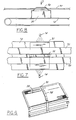
- Figure 7 is a top plan view of a heat exchanger core during a washing process; and
- Figure 8 is a side elevational view of the heat exchanger core of Figure 7 during a washing process.
-
- Referring now to the drawings, Figure 2 shows a heat exchanger, such as a
heater core 30, held by twoclamps heater core 30 includes a plurality ofinterleaved tubes 36 andfins 38 disposed between a pair of side supports 40. Fluid manifolds (or tanks) 42 are secured in fluid communication to thetubes 36 in known fashion. Theheater core 30 shown in Figure 2 is ready for brazing. Theclamps clamps clamps heater core 30, so that a compressive force can be maintained against the core by the clamps to hold the heater core in its predetermined position during the brazing process. - The
first clamp 32 extends betweenside support members 40 while the second clamp extends betweenfluid manifolds 42. As shown in Figure 3, thefirst clamp 32 is generally U-shaped and includes a pair ofleg members 50 and abight portion 52 interconnecting theleg members 50. Eachleg member 50 includes acontact portion 54 and anoutwardly end portion 56. The contact portions of eachleg member 54 contacts the side supports 40 to provide a compressive force on the heater core in a direction perpendicular to the longitudinal axis of thetubes 36. The outwardly extendingends 56 of the first clamp do not provide clamping force to the core. Rather, theseends 56 provide a cam-like surface to ease installation of theclamp 32 over the side supports. Also, theends 56 minimise the surface area of the clamp making contact with the side supports. This allows for easier removal of the clamp after brazing, since theends 56 do not braze to the core. - The
first clamps 32 also includes thebight portion 52 extending between theleg members 50. Thebight portion 52 includes an elevated, or steppedportion 58. Thestepped portion 58 provides a convenient handle for an operator to use when installing or removing theclamp 32 on thecore 30. Theclamp 32 typically is made as a single stamped member. - The
first clamp 32 also provides a second function. As will be explained in greater detail below, thestepped portion 58 of thefirst clamp 32 prevents thecore 30 from rotating while the core is subjected to a washing operation. As shown in Figures 7 and 8, thestepped portion 58 of theclamp 32 rides between a pair ofwash rails 70 located above a movingconveyor assembly 72. Prior to be being brazed, thecore 30 is subjected to a washing process in which a pair ofspray jets 74 force a cleaning solution over theentire core 30. This spray tends to cause the core to rotate or be knocked off the conveyor assembly. However, the steppedportion 58 keeps the core 30 in place. The length of the steppedportion 58 should extend over a majority of the length of the clamp to provide increased stability while the core is being washed. - The
second clamp 34 is structured very similar to thefirst clamp 32. Thesecond clamp 34 is also generally U-shaped and includes a pair of dependingleg members 60 and abight portion 62 extending between and connecting theleg members 60. As shown in Figure 5, eachleg member 60 is disposed at an acute angle, α, to the longitudinal plane of the bight portion. This angle is typically less than ten degrees. Thesecond clamp 34 extends between thefluid manifolds 42 and provides a compressive force parallel to the longitudinal axis of thetubes 36. Theleg members 60 include a contact segment comprising a raisedbump portion 66. Thisbump portion 66 contacts each of the manifolds 42. Thebump portion 66, in conjunction with the angled leg portion, provides a single point of contact by thesecond clamp 34 against themanifolds 42. This structure minimises the amount of surface area of the clamp contacting themanifolds 42 to prevent brazing of the clamp to the manifold. The bump portion is formed integrally with eachleg member 60. Alternatively, the bump can be secured to the leg meters by welding or adhesively fastening it thereto. - The
bight portion 62 extends between theleg members 60. Thebight portion 62 includes an elevated, or stepped portion 68. The stepped portion 68 extends over the steppedportion 58 of thefirst clamp 32 to provide a nested configuration. The stepped portion 68 of the second clamp also provides a convenient handle for an operator to use when installing or removing theclamp 34 on thecore 30. Theclamp 34 typically is made as a single stamped meter. - A method of assembling a
heater core 30 using the brazing clamps 32, 34 according to the present invention will now be described. The first step in such a method is to assemble a plurality of tubes andfins first clamp 32 is forced over this sub-assembly as shown in Figure 6. The sub-assembly is placed on a conveyor and carried to a wash station. As described above, the steppedportion 58 ofclamp 32 slides betweenrails 70 and the core is sprayed fromjets 74. - After cleaning, the
manifolds 42 are added to the cores and thesecond clamp 34 is placed over the core 30 as shown in Figure 2. It should be apparent that each of the components of the heater core 22 are coated with the appropriate brazing flux and materials to accomplish the brazing of the core. The core is then placed into a brazing furnace. The core is heated to a temperature sufficient to cause the core to braze together followed by a cooling stage prior to removing theclamps - It should be readily apparent to those skilled in the art that various modification and alterations of the present invention are readily available without departing from the spirit and scope of the present invention. For example, the clamps may be formed from a variety of materials, such as stainless steel in the preferred embodiment, and in a variety of configurations to accommodate heat exchangers of various shapes and sizes. The contact portions of each of the leg members of both clamps may be coated with different materials, such as ceramics, to prevent sticking or brazing of the clamp to the core. The clamps may be utilised a multiple number of times and to braze other heat exchangers, not simply heater cores.
Claims (9)
- An apparatus for holding a heat exchanger core during a manufacturing process, the core (30) including first and second side support members (40) disposed on opposite sides of an assembly of a plurality of interleaved tubes (36) and fins (38), the core (30) also including first and second fluid tanks (42) disposed on opposite ends of said tubes (36), said apparatus comprising:a first clamp (32) disposed between said first and second side support members (40), said first clamp including a pair of leg members (50) and a bight portion (52) interconnecting said leg members, each of said leg members having a contact portion (54) and an outwardly depending end portion (56), said contact portion (54) being configured to contact said side supports members (40) and apply a compressive force therebetween, said bight portion (52) including a stepped portion (58) extending above the plane of said bight portion; anda second clamp (34) extending between said first and second fluid tank (42) and configured to apply a compressive force therebetween,
whereby said first and second clamps (32,34) apply a constant compressive force in two perpendicular directions against said core to hold said core (30) together in a predetermined position during the manufacturing process and wherein said first and second clamps (32,34) are removed from said heat exchanger core after the manufacturing operation is completed. - An apparatus according to Claim 1, wherein said first clamp also includes means for preventing rotation of said core during a washing process.
- An apparatus according to Claim 2, wherein said means for preventing rotation of said core during a washing process comprises said stepped portion.
- An apparatus according to Claim 1, wherein said second clamp includes a pair of leg members and a bight portion interconnecting said leg members, each of said leg members having a contact portion being configured to contact said manifolds and apply a compressive force therebetween, said bight portion including a stepped portion extending above the plane of said bight portion.
- An apparatus according to Claim 4, wherein said leg members are disposed at an acute angle of less than ten degrees from the plane of the bight portion.
- An apparatus according to Claim 4, wherein said contact portions include a raised bump extending above the plane of the contact portion, the bump being configured to contact said manifolds when said clamp is placed over the manifolds.
- An apparatus for holding a heat exchanger core during a manufacturing process, the core including first and second side support members disposed on opposite sides of an assembly of a plurality of interleaved tubes and fins, the core also including a first and second fluid tank disposed on opposite ends of said tubes, said apparatus comprising:a first clamp disposed between said first and second side support members, said first clamp including a pair of leg members and a bight portion interconnecting said leg members, each of said leg members having a contact portion and an outwardly depending end portion, said contact portion being configured to contact said side supports members and apply a compressive force therebetween, said bight portion including a stepped portion extending above the plane of said bight portion, said stepped portion being configured to prevent rotation of said core during washing; anda second clamp extending between said first and second fluid tank and configured to apply a compressive force therebetween, said second clamp including a pair of leg members and a bight portion interconnecting said leg members, each of said leg members having a contact portion being configured to contact said manifolds and apply a compressive force therebetween, said bight portion including a stepped portion extending above the plane of said bight portion;
whereby said first and second clamps apply a constant compressive force in two perpendicular directions against said core to hold said core together in a predetermined position during the manufacturing process and wherein said first and second clamps are removed from said heat exchanger core after the manufacturing operation is completed. - An apparatus according to Claim 7, wherein said leg members of said second clamp are disposed at an acute angle of less than ten degrees from the plane of the bight portion.
- An apparatus according to Claim 8, wherein said contact portions include a raised bump extending above the plane of the contact portion, the bump being configured to contact said manifolds when said clamp is placed over the manifolds.
Applications Claiming Priority (2)
| Application Number | Priority Date | Filing Date | Title |
|---|---|---|---|
| US09/317,602 US6108899A (en) | 1999-05-24 | 1999-05-24 | Brazing fixture for a heat exchanger |
| US317602 | 1999-05-24 |
Publications (1)
| Publication Number | Publication Date |
|---|---|
| EP1057566A2 true EP1057566A2 (en) | 2000-12-06 |
Family
ID=23234425
Family Applications (1)
| Application Number | Title | Priority Date | Filing Date |
|---|---|---|---|
| EP00304222A Withdrawn EP1057566A2 (en) | 1999-05-24 | 2000-05-18 | Brazing fixture for a heat exchanger. |
Country Status (2)
| Country | Link |
|---|---|
| US (1) | US6108899A (en) |
| EP (1) | EP1057566A2 (en) |
Cited By (1)
| Publication number | Priority date | Publication date | Assignee | Title |
|---|---|---|---|---|
| CN113600960A (en) * | 2021-10-08 | 2021-11-05 | 山东中茂散热器有限公司 | Clamping and bearing device for welding radiator core |
Families Citing this family (11)
| Publication number | Priority date | Publication date | Assignee | Title |
|---|---|---|---|---|
| JP4094806B2 (en) * | 2000-12-28 | 2008-06-04 | カルソニックカンセイ株式会社 | Manufacturing method of heat exchanger |
| US20030183376A1 (en) * | 2002-04-02 | 2003-10-02 | Abell Bradley David | High strength CAB brazed heat exchangers using high strength fin materials |
| EP1384544A1 (en) * | 2002-07-26 | 2004-01-28 | Behr Lorraine S.A.R.L. | Heat exchanger brazing apparatus |
| FR2896863B1 (en) * | 2006-02-01 | 2008-07-04 | Valeo Systemes Thermiques | DEVICE FOR HOLDING HEAT EXCHANGER BEAM FOR BRAZING AND ASSOCIATED SUPPORTING DEVICE |
| US7641101B2 (en) * | 2006-10-10 | 2010-01-05 | International Business Machines Corporation | Method of assembling a cooling system for a multi-component electronics system |
| US7751918B2 (en) * | 2007-01-05 | 2010-07-06 | International Business Machines Corporation | Methods for configuring tubing for interconnecting in-series multiple liquid-cooled cold plates |
| US20090086432A1 (en) * | 2007-09-27 | 2009-04-02 | International Business Machines Corporation | Docking station with closed loop airlfow path for facilitating cooling of an electronics rack |
| US8387249B2 (en) * | 2007-11-19 | 2013-03-05 | International Business Machines Corporation | Apparatus and method for facilitating servicing of a liquid-cooled electronics rack |
| JP6909283B2 (en) * | 2016-05-20 | 2021-07-28 | アレリス、ロールド、プロダクツ、ジャーマニー、ゲゼルシャフト、ミット、ベシュレンクテル、ハフツングAleris Rolled Products Germany Gmbh | Methods and equipment for manufacturing brazed heat exchangers |
| CN112894049A (en) * | 2020-12-25 | 2021-06-04 | 南京工业大学 | High-temperature brazing flexible bundling device and method for large plate-fin heat exchanger core |
| CN113579403A (en) * | 2021-08-02 | 2021-11-02 | 南京工业大学 | Multi-lap-plate movable positioning brazing clamp |
Family Cites Families (5)
| Publication number | Priority date | Publication date | Assignee | Title |
|---|---|---|---|---|
| FR2194928B1 (en) * | 1972-08-04 | 1975-03-07 | Chausson Usines Sa | |
| US4700469A (en) * | 1986-03-24 | 1987-10-20 | General Motors Corporation | Detachable clamp for fixturing heat exchanger core assemblies for brazing in combination with the heat exchanger core |
| US4743003A (en) * | 1987-03-09 | 1988-05-10 | Dietlein Robert W | Ski vise with rotating jaws |
| US5165163A (en) * | 1990-12-24 | 1992-11-24 | Ford Motor Company | Adjustable brazing fixture having levers responsive to the weight of a heat exchanger |
| US5450997A (en) * | 1993-06-28 | 1995-09-19 | Ford Motor Company | Brazing fixture for heat exchanger |
-
1999
- 1999-05-24 US US09/317,602 patent/US6108899A/en not_active Expired - Fee Related
-
2000
- 2000-05-18 EP EP00304222A patent/EP1057566A2/en not_active Withdrawn
Cited By (2)
| Publication number | Priority date | Publication date | Assignee | Title |
|---|---|---|---|---|
| CN113600960A (en) * | 2021-10-08 | 2021-11-05 | 山东中茂散热器有限公司 | Clamping and bearing device for welding radiator core |
| CN113600960B (en) * | 2021-10-08 | 2021-12-07 | 山东中茂散热器有限公司 | Clamping and bearing device for welding radiator core |
Also Published As
| Publication number | Publication date |
|---|---|
| US6108899A (en) | 2000-08-29 |
Similar Documents
| Publication | Publication Date | Title |
|---|---|---|
| US6108899A (en) | Brazing fixture for a heat exchanger | |
| US5881456A (en) | Header tubes for heat exchangers and the methods used for their manufacture | |
| KR101554053B1 (en) | Sealing means for a heat exchanger header box | |
| JPH0253132B2 (en) | ||
| JPH05203091A (en) | Header jig | |
| KR900002726B1 (en) | Detachable clamp for ixturing heat exchanger core assemblies for brazing | |
| US5450997A (en) | Brazing fixture for heat exchanger | |
| EP1065464A1 (en) | Heat exchanger with variable compression side support | |
| US4611743A (en) | Device for aligning a weldolet and a pipe to be joined | |
| JPS63188434A (en) | Method and device for expanding and levelling tube for plate fin type heat exchanger | |
| JPH07151488A (en) | Heat exchanger and manufacture thereof | |
| US5070608A (en) | Method for gripping tubes in multirow plate fin coils | |
| JPH04274872A (en) | Adjustable soldering fixing tool | |
| JP4043079B2 (en) | Heat exchanger header pipe | |
| JPH0765868B2 (en) | Method for manufacturing aluminum heat exchanger core | |
| JP2990246B2 (en) | Aluminum heat exchanger core | |
| JP3501064B2 (en) | Cross-fin coil expansion method | |
| CN101023274A (en) | Pipe clamps for reinforcement grids especially for connection to underfloor heating | |
| JPH05118774A (en) | Laminated heat exchanger | |
| JPS6218857Y2 (en) | ||
| KR0119612Y1 (en) | Assembly jig of automobile condenser | |
| JPH0712773U (en) | Heat exchanger | |
| JPH0367788B2 (en) | ||
| JPS63183735A (en) | Method and device for machining partially assembled plate fin type heat exchanger | |
| JPH06201288A (en) | Heat exchanger and manufacture thereof |
Legal Events
| Date | Code | Title | Description |
|---|---|---|---|
| PUAI | Public reference made under article 153(3) epc to a published international application that has entered the european phase |
Free format text: ORIGINAL CODE: 0009012 |
|
| AK | Designated contracting states |
Kind code of ref document: A2 Designated state(s): AT BE CH CY DE DK ES FI FR GB GR IE IT LI LU MC NL PT SE |
|
| AX | Request for extension of the european patent |
Free format text: AL;LT;LV;MK;RO;SI |
|
| STAA | Information on the status of an ep patent application or granted ep patent |
Free format text: STATUS: THE APPLICATION HAS BEEN WITHDRAWN |
|
| 18W | Application withdrawn |
Withdrawal date: 20020409 |