EP1057325B1 - Studio camera viewfinder - Google Patents
Studio camera viewfinder Download PDFInfo
- Publication number
- EP1057325B1 EP1057325B1 EP99972404A EP99972404A EP1057325B1 EP 1057325 B1 EP1057325 B1 EP 1057325B1 EP 99972404 A EP99972404 A EP 99972404A EP 99972404 A EP99972404 A EP 99972404A EP 1057325 B1 EP1057325 B1 EP 1057325B1
- Authority
- EP
- European Patent Office
- Prior art keywords
- viewfinder
- camera
- studio
- adjustment mechanism
- studio camera
- Prior art date
- Legal status (The legal status is an assumption and is not a legal conclusion. Google has not performed a legal analysis and makes no representation as to the accuracy of the status listed.)
- Expired - Lifetime
Links
Images
Classifications
-
- H—ELECTRICITY
- H04—ELECTRIC COMMUNICATION TECHNIQUE
- H04N—PICTORIAL COMMUNICATION, e.g. TELEVISION
- H04N5/00—Details of television systems
- H04N5/222—Studio circuitry; Studio devices; Studio equipment
-
- H—ELECTRICITY
- H04—ELECTRIC COMMUNICATION TECHNIQUE
- H04N—PICTORIAL COMMUNICATION, e.g. TELEVISION
- H04N23/00—Cameras or camera modules comprising electronic image sensors; Control thereof
- H04N23/60—Control of cameras or camera modules
- H04N23/63—Control of cameras or camera modules by using electronic viewfinders
-
- H—ELECTRICITY
- H04—ELECTRIC COMMUNICATION TECHNIQUE
- H04N—PICTORIAL COMMUNICATION, e.g. TELEVISION
- H04N23/00—Cameras or camera modules comprising electronic image sensors; Control thereof
- H04N23/50—Constructional details
- H04N23/53—Constructional details of electronic viewfinders, e.g. rotatable or detachable
- H04N23/531—Constructional details of electronic viewfinders, e.g. rotatable or detachable being rotatable or detachable
Definitions
- the invention relates to a viewfinder for a studio camera, and to a studio camera provided with a viewfinder.
- Studio camera viewfinders are hand-adjusted to allow the camera operator to have a good view on what is picked up by the camera.
- viewfinder having an LCD display known for having a large viewing angle dependency of the display, it is very important that the camera operator continuously has a good view on the viewfinder display.
- the viewfinder is provided with a pan and tilt mechanism that is to be operated by the camera operator, who for this purpose, has to remove his hands from the camera controls (sharpness, zooming, pan, tilt).
- US 5,548,334 discloses a video camera having a viewfinder which is rotatably mounted on a camera body.
- a motor is connected with a rotatable viewfinder to maintain a comfortable position of the viewfinder for the cameraman whatever the shooting position is.
- a studio camera comprising an image pickup unit for converting a scene into image signals, and a viewfinder for displaying the image signals on a viewfinder display, the viewfinder having a position adjustment mechanism for allowing a camera operator to have an optimal view on the viewfinder display, the position adjustment mechanism is automatically controlled so as to direct the viewfinder display to the camera operator.
- the studio camera SC comprises an image pickup unit PUU and a viewfinder VF.
- the viewfinder VF has a position adjustment mechanism PAM to automatically direct a viewfinder display D to a camera operator CO.
- the position adjustment mechanism PAM just has a tilt motor M.
- the position adjustment mechanism PAM is controlled by a receiver REC that receives position information signals from a transmitter TRANSM unit mounted on a head H of the camera operator CO.
- the transmitter unit TRANSM has a device for attaching the transmitter to the head H, and a proper transmitter T.
- the viewfinder VF is provided with a (tilt) motor M which is controlled by a transmitter TRANSM, preferably an optical transmitter, mounted on the cameraman's head H, preferably in his headphone, in such a manner that the viewfinder display D is always directed to the camera operator's face.
- a transmitter TRANSM preferably an optical transmitter
- the viewfinder's position adjustment mechanism comprises a gyroscope to ensure that the viewfinder display stays directed to the camera operator's face even if the image pickup unit is moved.
- any reference signs placed between parentheses shall not be construed as limiting the claim.
- the word "comprising” does not exclude the presence of other elements or steps than those listed in a claim.
- the invention can be implemented by means of hardware comprising several distinct elements, and by means of a suitably programmed computer. In the device claim enumerating several means, several of these means can be embodied by one and the same item of hardware.
Abstract
Description
- The invention relates to a viewfinder for a studio camera, and to a studio camera provided with a viewfinder.
- Studio camera viewfinders are hand-adjusted to allow the camera operator to have a good view on what is picked up by the camera. Especially for viewfinder having an LCD display, known for having a large viewing angle dependency of the display, it is very important that the camera operator continuously has a good view on the viewfinder display. To adjust the viewfinder orientation, the viewfinder is provided with a pan and tilt mechanism that is to be operated by the camera operator, who for this purpose, has to remove his hands from the camera controls (sharpness, zooming, pan, tilt).
- In
US 4,118,720 a mechanical viewfinder eyepiece leveling device is described. The known device maintains the eyepiece in its position even if a camera mounted on a support member is tilted about a horizontal axis. The device facilitates the operation of the camera for the cameraman. -
US 5,548,334 discloses a video camera having a viewfinder which is rotatably mounted on a camera body. A motor is connected with a rotatable viewfinder to maintain a comfortable position of the viewfinder for the cameraman whatever the shooting position is. - It is, inter alia, an object of the invention to facilitate a camera operator's work. To this end, primary aspects of the invention provide a camera viewfinder unit and a studio camera, as defined in the claims.
- In a studio camera in accordance with the present invention, comprising an image pickup unit for converting a scene into image signals, and a viewfinder for displaying the image signals on a viewfinder display, the viewfinder having a position adjustment mechanism for allowing a camera operator to have an optimal view on the viewfinder display, the position adjustment mechanism is automatically controlled so as to direct the viewfinder display to the camera operator.
- These and other aspects of the invention will be apparent from and elucidated with reference to the embodiments described hereinafter.
- In the drawings:
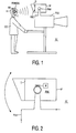
- Fig. 1 shows an embodiment of a studio camera in accordance with the present invention; and
- Fig. 2 shows parts of the studio camera of Fig. 1 in more detail.
- In the embodiment of Figs. 1 and 2, the studio camera SC comprises an image pickup unit PUU and a viewfinder VF. The viewfinder VF has a position adjustment mechanism PAM to automatically direct a viewfinder display D to a camera operator CO. In a simple embodiment, the position adjustment mechanism PAM just has a tilt motor M. Obviously, in more complex embodiments, other movements like panning are also possible. The position adjustment mechanism PAM is controlled by a receiver REC that receives position information signals from a transmitter TRANSM unit mounted on a head H of the camera operator CO. The transmitter unit TRANSM has a device for attaching the transmitter to the head H, and a proper transmitter T.
- So, in a preferred embodiment, to ensure that a viewfinder VF is always directed to a camera operator's face (especially important if the viewfinder display D is an LCD having a viewing angle dependent visibility), the viewfinder VF is provided with a (tilt) motor M which is controlled by a transmitter TRANSM, preferably an optical transmitter, mounted on the cameraman's head H, preferably in his headphone, in such a manner that the viewfinder display D is always directed to the camera operator's face. Advantage: now that the camera operator CO no longer needs to adjust the viewfinder (tilt) angle manually, he can use both hands for controlling the camera SC.
- It should be noted that the above-mentioned embodiments illustrate rather than limit the invention, and that those skilled in the art will be able to design many alternative embodiments without departing from the scope of the appended claims. In one alternative embodiment, the viewfinder's position adjustment mechanism comprises a gyroscope to ensure that the viewfinder display stays directed to the camera operator's face even if the image pickup unit is moved. In the claims, any reference signs placed between parentheses shall not be construed as limiting the claim. The word "comprising" does not exclude the presence of other elements or steps than those listed in a claim. The invention can be implemented by means of hardware comprising several distinct elements, and by means of a suitably programmed computer. In the device claim enumerating several means, several of these means can be embodied by one and the same item of hardware.
Claims (3)
- Studio camera viewfinder (VF), comprising:a viewfinder display (D) for displaying image signals from an image pickup unit (PUU); anda position adjustment mechanism (PAM) comprising at least one motor (M) for allowing a camera operator (CO) to have an optimal view on the viewfinder display (D), wherein the at least one motor (M) of the position adjustment mechanism (PAM) is controlled by a receiver (REC) for receiving position information signals from a transmitter unit (TRANSM) attached to the camera operator (CO) such that the viewfinder display (D) is automatically directed to the camera operator (CO).
- Studio camera (SC), comprising:an image pickup unit (PUU) for converting a scene into image signals; anda viewfinder (VF) according to claim 1.
- Studio camera system comprising a studio camera according to claim 2 and a transmitter unit (TRANSM) cooperating with the receiver (REC) of the studio camera.
Priority Applications (1)
| Application Number | Priority Date | Filing Date | Title |
|---|---|---|---|
| EP99972404A EP1057325B1 (en) | 1998-11-18 | 1999-11-02 | Studio camera viewfinder |
Applications Claiming Priority (4)
| Application Number | Priority Date | Filing Date | Title |
|---|---|---|---|
| EP98203907 | 1998-11-18 | ||
| EP98203907 | 1998-11-18 | ||
| PCT/EP1999/008340 WO2000030347A1 (en) | 1998-11-18 | 1999-11-02 | Studio camera viewfinder |
| EP99972404A EP1057325B1 (en) | 1998-11-18 | 1999-11-02 | Studio camera viewfinder |
Publications (2)
| Publication Number | Publication Date |
|---|---|
| EP1057325A1 EP1057325A1 (en) | 2000-12-06 |
| EP1057325B1 true EP1057325B1 (en) | 2008-01-09 |
Family
ID=8234359
Family Applications (1)
| Application Number | Title | Priority Date | Filing Date |
|---|---|---|---|
| EP99972404A Expired - Lifetime EP1057325B1 (en) | 1998-11-18 | 1999-11-02 | Studio camera viewfinder |
Country Status (5)
| Country | Link |
|---|---|
| US (1) | US6253032B1 (en) |
| EP (1) | EP1057325B1 (en) |
| JP (1) | JP4306968B2 (en) |
| DE (1) | DE69937947T2 (en) |
| WO (1) | WO2000030347A1 (en) |
Families Citing this family (4)
| Publication number | Priority date | Publication date | Assignee | Title |
|---|---|---|---|---|
| JP3357628B2 (en) * | 1999-04-16 | 2002-12-16 | 池上通信機株式会社 | Viewfinder control device and television camera |
| US7742073B1 (en) * | 2000-11-01 | 2010-06-22 | Koninklijke Philips Electronics N.V. | Method and apparatus for tracking an object of interest using a camera associated with a hand-held processing device |
| US7083291B1 (en) | 2002-10-24 | 2006-08-01 | Peter Yong | Glare shield for camera |
| JP4840403B2 (en) * | 2008-04-30 | 2011-12-21 | ソニー株式会社 | Information recording apparatus, imaging apparatus, information recording method, and program |
Family Cites Families (10)
| Publication number | Priority date | Publication date | Assignee | Title |
|---|---|---|---|---|
| US4118720A (en) * | 1977-01-03 | 1978-10-03 | Panavision, Incorporated | Viewfinder eyepiece leveling device |
| US4672436A (en) | 1986-02-05 | 1987-06-09 | Louis Hawthorne | Integrated camcorder viewing and support system |
| US5548334A (en) * | 1990-01-11 | 1996-08-20 | Canon Kabushiki Kaisha | Video camera having viewfinder rotatably mounted on camera body |
| US5432597A (en) * | 1990-05-31 | 1995-07-11 | Parkervision, Inc. | Remote controlled tracking system for tracking a remote-control unit and positioning and operating a camera and method |
| US5491510A (en) | 1993-12-03 | 1996-02-13 | Texas Instruments Incorporated | System and method for simultaneously viewing a scene and an obscured object |
| GB9415660D0 (en) | 1994-08-03 | 1994-09-21 | Lam David C S | Multi-part camera |
| JPH0898066A (en) | 1994-09-27 | 1996-04-12 | Kazumi Numata | Separation of video camera main body from finder |
| US5734421A (en) * | 1995-05-30 | 1998-03-31 | Maguire, Jr.; Francis J. | Apparatus for inducing attitudinal head movements for passive virtual reality |
| KR0185928B1 (en) * | 1995-10-07 | 1999-05-01 | 김광호 | Automatic direction control apparatus for lcd monitor |
| JP3397602B2 (en) * | 1996-11-11 | 2003-04-21 | 富士通株式会社 | Image display apparatus and method |
-
1999
- 1999-11-02 EP EP99972404A patent/EP1057325B1/en not_active Expired - Lifetime
- 1999-11-02 DE DE69937947T patent/DE69937947T2/en not_active Expired - Lifetime
- 1999-11-02 JP JP2000583244A patent/JP4306968B2/en not_active Expired - Fee Related
- 1999-11-02 WO PCT/EP1999/008340 patent/WO2000030347A1/en active IP Right Grant
- 1999-11-18 US US09/442,962 patent/US6253032B1/en not_active Expired - Lifetime
Non-Patent Citations (1)
| Title |
|---|
| None * |
Also Published As
| Publication number | Publication date |
|---|---|
| EP1057325A1 (en) | 2000-12-06 |
| US6253032B1 (en) | 2001-06-26 |
| WO2000030347A1 (en) | 2000-05-25 |
| DE69937947T2 (en) | 2009-01-02 |
| JP4306968B2 (en) | 2009-08-05 |
| JP2002530944A (en) | 2002-09-17 |
| DE69937947D1 (en) | 2008-02-21 |
Similar Documents
| Publication | Publication Date | Title |
|---|---|---|
| US6853809B2 (en) | Camera system for providing instant switching between wide angle and full resolution views of a subject | |
| US5959605A (en) | Video magnifier | |
| EP0878962B1 (en) | Image pickup system with separate viewfinder and microphone/controller | |
| US5300976A (en) | Movie camera system having view finding and projecting operations | |
| CA2448678A1 (en) | Hand-held remote control and display system for film and video cameras and lenses | |
| US5027219A (en) | Apparatus and method for converting pictures or images into video signals | |
| US6956616B2 (en) | Apparatus for facilitating viewing by human eye | |
| US5801774A (en) | Camcorder with detachable and rotatable viewfinder assembly | |
| US5631699A (en) | Video camera system for use in fixed and free modes in which, when coupled to a base in the fixed mode, video functions are automatically set by a control | |
| US5436654A (en) | Lens tilt mechanism for video teleconferencing unit | |
| EP1057325B1 (en) | Studio camera viewfinder | |
| US7140789B1 (en) | Remote controlled pan head system for video cameras and its method of operation | |
| JP2004187140A (en) | Document presenting apparatus | |
| GB2240445A (en) | Video camera including detachable view-finder | |
| EP1045579B1 (en) | Viewfinder control unit and television camera | |
| JP4444758B2 (en) | Television camera device | |
| JPH0964777A (en) | Radio video signal transmitter-receiver | |
| JPH1023300A (en) | Television camera | |
| JPH05207348A (en) | Video camera | |
| KR19990086124A (en) | Controller with video indicator | |
| US20190204643A1 (en) | Dynamic LCD Screen | |
| CN115379111A (en) | Remote control device | |
| JP2001045451A (en) | Communication terminal and remote work support communication equipment using the same | |
| JPH07245749A (en) | Image pickup display device | |
| KR19980051197U (en) | Camera position adjustment and image device by remote control |
Legal Events
| Date | Code | Title | Description |
|---|---|---|---|
| PUAI | Public reference made under article 153(3) epc to a published international application that has entered the european phase |
Free format text: ORIGINAL CODE: 0009012 |
|
| AK | Designated contracting states |
Kind code of ref document: A1 Designated state(s): DE FR GB |
|
| 17P | Request for examination filed |
Effective date: 20001127 |
|
| RAP1 | Party data changed (applicant data changed or rights of an application transferred) |
Owner name: BTS HOLDING INTERNATIONAL B.V. |
|
| GRAP | Despatch of communication of intention to grant a patent |
Free format text: ORIGINAL CODE: EPIDOSNIGR1 |
|
| GRAS | Grant fee paid |
Free format text: ORIGINAL CODE: EPIDOSNIGR3 |
|
| GRAA | (expected) grant |
Free format text: ORIGINAL CODE: 0009210 |
|
| AK | Designated contracting states |
Kind code of ref document: B1 Designated state(s): DE FR GB |
|
| REG | Reference to a national code |
Ref country code: GB Ref legal event code: FG4D |
|
| REF | Corresponds to: |
Ref document number: 69937947 Country of ref document: DE Date of ref document: 20080221 Kind code of ref document: P |
|
| ET | Fr: translation filed | ||
| RAP2 | Party data changed (patent owner data changed or rights of a patent transferred) |
Owner name: THOMSON LICENSING S.A. |
|
| PLBE | No opposition filed within time limit |
Free format text: ORIGINAL CODE: 0009261 |
|
| STAA | Information on the status of an ep patent application or granted ep patent |
Free format text: STATUS: NO OPPOSITION FILED WITHIN TIME LIMIT |
|
| 26N | No opposition filed |
Effective date: 20081010 |
|
| REG | Reference to a national code |
Ref country code: FR Ref legal event code: PLFP Year of fee payment: 17 |
|
| PGFP | Annual fee paid to national office [announced via postgrant information from national office to epo] |
Ref country code: DE Payment date: 20151126 Year of fee payment: 17 Ref country code: GB Payment date: 20151130 Year of fee payment: 17 |
|
| PGFP | Annual fee paid to national office [announced via postgrant information from national office to epo] |
Ref country code: FR Payment date: 20151120 Year of fee payment: 17 |
|
| REG | Reference to a national code |
Ref country code: DE Ref legal event code: R119 Ref document number: 69937947 Country of ref document: DE |
|
| GBPC | Gb: european patent ceased through non-payment of renewal fee |
Effective date: 20161102 |
|
| REG | Reference to a national code |
Ref country code: FR Ref legal event code: ST Effective date: 20170731 |
|
| PG25 | Lapsed in a contracting state [announced via postgrant information from national office to epo] |
Ref country code: FR Free format text: LAPSE BECAUSE OF NON-PAYMENT OF DUE FEES Effective date: 20161130 |
|
| PG25 | Lapsed in a contracting state [announced via postgrant information from national office to epo] |
Ref country code: GB Free format text: LAPSE BECAUSE OF NON-PAYMENT OF DUE FEES Effective date: 20161102 Ref country code: DE Free format text: LAPSE BECAUSE OF NON-PAYMENT OF DUE FEES Effective date: 20170601 |