EP1056923B1 - System, apparatus and method for facilitating retrieval of an item from a well - Google Patents
System, apparatus and method for facilitating retrieval of an item from a well Download PDFInfo
- Publication number
- EP1056923B1 EP1056923B1 EP99901717A EP99901717A EP1056923B1 EP 1056923 B1 EP1056923 B1 EP 1056923B1 EP 99901717 A EP99901717 A EP 99901717A EP 99901717 A EP99901717 A EP 99901717A EP 1056923 B1 EP1056923 B1 EP 1056923B1
- Authority
- EP
- European Patent Office
- Prior art keywords
- mandrel
- item
- gripping means
- movable
- arm
- Prior art date
- Legal status (The legal status is an assumption and is not a legal conclusion. Google has not performed a legal analysis and makes no representation as to the accuracy of the status listed.)
- Expired - Lifetime
Links
- 238000005520 cutting process Methods 0.000 claims description 14
- 239000012530 fluid Substances 0.000 description 5
- 239000003381 stabilizer Substances 0.000 description 5
- 125000006850 spacer group Chemical group 0.000 description 4
- 230000004913 activation Effects 0.000 description 2
- 229910000760 Hardened steel Inorganic materials 0.000 description 1
- 229910000831 Steel Inorganic materials 0.000 description 1
- 244000309464 bull Species 0.000 description 1
- 238000011010 flushing procedure Methods 0.000 description 1
- 230000002401 inhibitory effect Effects 0.000 description 1
- 239000000463 material Substances 0.000 description 1
- 239000010959 steel Substances 0.000 description 1
- 238000003466 welding Methods 0.000 description 1
Images


Classifications
-
- E—FIXED CONSTRUCTIONS
- E21—EARTH OR ROCK DRILLING; MINING
- E21B—EARTH OR ROCK DRILLING; OBTAINING OIL, GAS, WATER, SOLUBLE OR MELTABLE MATERIALS OR A SLURRY OF MINERALS FROM WELLS
- E21B31/00—Fishing for or freeing objects in boreholes or wells
- E21B31/12—Grappling tools, e.g. tongs or grabs
- E21B31/18—Grappling tools, e.g. tongs or grabs gripping externally, e.g. overshot
-
- E—FIXED CONSTRUCTIONS
- E21—EARTH OR ROCK DRILLING; MINING
- E21B—EARTH OR ROCK DRILLING; OBTAINING OIL, GAS, WATER, SOLUBLE OR MELTABLE MATERIALS OR A SLURRY OF MINERALS FROM WELLS
- E21B31/00—Fishing for or freeing objects in boreholes or wells
- E21B31/12—Grappling tools, e.g. tongs or grabs
- E21B31/16—Grappling tools, e.g. tongs or grabs combined with cutting or destroying means
Definitions
- This invention relates to a system and an apparatus for facilitating retrieval of an item from a well and more particularly, but not exclusively, for retrieving a well head from a sub-sea well.
- a well head is used to control the flow of well fluids in a well bore.
- the well head is usually located at the top of the well bore. In marine environments the well head is usually located on the seabed.
- the well head is generally mounted on a base plate and attached to a casing string which forms part of the well bore.
- GB-A-2 259 930 discloses a tool suspended on a drill string, which tool comprises a grapple for engaging the top of a string of casing to which a well head is attached and which is to be retrieved.
- the tool further comprises a mud motor and a rotary cutter depending from a rotor of the mud motor for cutting the casing at a location below the grapple.
- the well head can be cut and lifted to the surface in one operation.
- the first aspect of the present invention attempts to reduce this problem.
- an apparatus for facilitating retrieval of an item from a well having the features as set forth in claim 1.
- said apparatus further comprises a mandrel, said means for engaging an item, for example a well head, mounted thereon.
- said locking means is actuable by movement of said mandrel.
- one of said mandrel and said means comprises at least one lug moveably arranged in a channel in the other of said mandrel and said means, such that, in use, one of said lug and said channel can move from a first position in which said means is able to release said item to a second position in which said means is inhibited from releasing said item.
- one of lug and said channel in use, moves from said first position to said second position on rotation of said mandrel with respect to said means.
- one of said lug and said channel in use, moves from said first position to said second position by longitudinal movement of said mandrel with respect to said means.
- one of said lug and said channel in use, moves from said first position to said second position by a combination of rotating said mandrel and longitudinal movement of said mandrel with respect to said means.
- said means comprises a housing and at least one arm moveable thereon.
- said at least one arm is moveable about a pivot on said housing.
- said mandrel comprises a shoulder, which in use, moves said arm into engagement with said item to be retrieved upon movement of said mandrel.
- said system further comprises a mud motor.
- Figure 1 shows a system for retrieving a well head.
- the system is generally identified by reference numeral 10.
- the system 10 comprises an apparatus 20 and a casing cutter 30 arranged therebelow.
- An upper part 40' of a mud motor 12 is positioned in a drill string 14.
- Two safety clamps 16 are secured around the upper part of the mud motor 12.
- a lower part 22 of a central mandrel 21 of the apparatus 20 is threadedly connected to a stabilizer 18.
- a lower part 40 of mud motor 12 (e.g. as is typical with a bearing assembly and into which the power shaft extends) is connected in the string 14 below the stabilizer 18 and a lower stabilizer 18' is connected below the lower part 40 of the mud motor 12.
- the casing cutter 30 is threadedly connected below the lower stabilizer 18'.
- a bull sub 42, made of rubber-coated steel is connected below the casing cutter 30 and inhibits damage to the wellhead as the apparatus is moved through it prior to cutting of the casing.
- the safety clamps 16 are used on the upper part 40' of the mud motor 12 above the gripping apparatus to limit the dowmward movement of the upper part 40' of the mud motor 12 thereby limitimg the length of casing that is cut (and to be retrieved) and to ensure that cutting ceases at a desired point.
- a drill string is used that is rotatable (e.g. in a common rotary rig) without a mud motor
- no safety clamps are used; and, in one aspect of such a system, a marine swivel is used on top of the system 10 to facilitate rotation.
- Figure 2 shows a system generally identified by reference numeral 50.
- the system 50 is similar to the system 10 shown in Figure 1, with the addition of a drain sub 44 located between the lower stabilizer 18' and the casing cutter 30.
- the drain sub 44 exhausts into a wellbore annulus outside the drain sub 44 above the cutting blades 31. This reduces the pressure drop across the casing cutter 30 or increases the pressure above the casing cutter 30 to that below the cutting blades 31.
- the reduction in fluid pressure across the cutting tool 30 results in a reduced tendency for swarf including cuttings and debris to be pumped up the wellbore annulus.
- a portion of the fluid under pressure flowing from the lower part 40 of the mud motor flows through the cutting tool 30 and is applied thereto in order to maintain activation of the cutting blades 31.
- Figure 6 shows the drain sub 44 which has a flow bore 121 therethrough from top to bottom and an exhaust port 122 in the wall 44 thereof.
- the system 50 may include any known drain sub or dump sub or a sub with orifices or ports originally blocked by ruptureable discs or shear members.
- An orifice 123 is held in place in the exhaust port 122 by a snap ring 124. Use of such an orifice 123, or one of a series of orifices with different inner diameters, permits precise control of the fluid flowing from the drain sub 44.
- the exhaust port 122 is angled downwards towards the blades of the casing cutter 30, when the cutting blades 31 are in an extended position.
- the total flow to the mud motor 12 is about 3300 litres per minute (875 gallons per minute), the flow out the exhaust port 122 is about 1800 litres per minute (475 gallons per minute), and the flow to the cutting tool 30 is about 1500 litres per minute (400 gallons per minute).
- the orifice 123 has a diameter of about 1.75cm (0.689 inches) and the exhaust port 122 has a diameter of about 1.9cm (0.75 inches).
- the drain sub 44 can be positioned anywhere below the lower part 40 of the mud motor 12 and above the casing cutter 30.
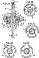
- FIG 3A shows a part of the apparatus 20.
- the central mandrel 21 has a flow bore 67 therethrough and extends movably longitudinally and rotatably through a bonnet 23 and through a housing 24.
- the housing 24 has a three arm supports 25, each provided with a pin 26 about which each arm 28 is moveable.
- Each pin 26 is made from hardened steel or a similar material, and secured in a slot 27 in each arm support 25.
- Each pin 26 may be circular or, in one aspect they may be elongated (as viewed from above) and shaped to correspond to the shape of each slot 27.
- Each arm 28 is pivotably and latchably mounted on each pin 26 so that upon upward movement of the central mandrel 21 an upper shoulder 29 thereof contacts a lower surface 61 of the arms 28 causing them to pivot downwardly in arm slots 161 of the housing to a position as shown in Figure 3A with a lip latch portion 62 engaging an item to be held, for example, a wellhead (not shown).
- a spline spacer 46 (Figure 5B) is secured on the central mandrel 21, by bolts and/or welding.
- the top 48 of the spline spacer 46 serves to assure correct positioning of the central mandrel 21 with respect to the housing 24 both for correct activation of each arm 28 and to correctly position co-operative locking apparatus to be described below.
- a spring (not shown) may be disposed between each arm 28 and the bonnet 23 to urge each arm 28 to an unlatched position.
- the bonnet 23 is secured to the housing 24 with a series of bolts 52 extending through a series of support pillars 54 placed between the bonnet 23 and the housing 24.
- the bonnet 23 also sits on pillars 152 extending upwardly from the housing 24.
- Holes 154 permit fluid under pressure to flow to a top surface 56 of the arms 28 to flush debris and cuttings away so that proper movement of the arms 28 is not impeded when the central mandrel 21 moves up to activate the arms.
- Figures 3F and 3G show an end view of an end 58 of one of the arms 28, illustrating a series of notches or valleys 59 (Figure 3F) or one notch 59a ( Figure 3G) made or formed integrally in the arm. These notches or valleys may collect debris in such a way that it does not impede proper arm movement. They also facilitate flushing of debris from the top of the arm by providing a channel for movement therefrom.
- the system and apparatus according to the present invention can be used, among other things, to retrieve a wellhead and the parts that engage and/or accommodate the wellhead can be customized, configured, and positioned for any particular wellhead.
- FIG. 3B to 3E there is shown the central mandrel 21 with a plurality of projecting lugs 66 which are positioned for movement into and out of a groove 68 which extends around an interior of the housing 24 and into which, through slots 72 in the housing 24, the lugs 66 are movable to achieve co-operative releasable locking of the mandrel 21 in place.
- the slots 72 permit the lugs 66 to move into alignment with the groove 68 as the central mandrel 21 is raised (and the latching arms 28 grip a wellhead) so the lugs 66 can then be rotated into the groove 68.
- the lugs 66 move up within the housing 24 in slots 72 until they are at the level of the groove 68. Then the central mandrel 21 is rotated (to the left about 60 degrees - counter-clockwise viewed from above) to move the lugs 66 into the groove 68, thus releasably locking the central mandrel 21 in place so that the arms 28, now engaging an item, such as a wellhead, and inhibiting inadvertent release.
- Lugs 77 projecting downwardly from the housing 24 are movable in the areas 171 of the spline spacer 46.
- the lugs 66 enter the groove 68 it is the lugs 77 abutting the raised areas 78 of the spline spacer 46 that stop movement of the lugs 66 in the groove 68 and prevent the lugs 66 from entering the next slot 72 in the housing 24, i.e., it is the stopping of the lugs 77 that prevents the central mandrel 21 from unlocking from the housing 24, that is until the central mandrel's rotation is reversed (right-hand rotation) to again align the lugs 66 with a slot 72 and thereby free the lugs 66 from the groove 68.
- FIG 7A shows a central mandrel 100 like the central mandrel 21 which is particularly suited for an embodiment of the present invention in which a marine swivel is used as described herein.
- a system according to the present invention may be like the systems of Figs. 1 and 2, but without any mud motor or safety clamps.
- a marine swivel is disposed on top of the bonnet 23 and the marine swivel preferably has a lower beveled edge that corresponds to a top beveled edge of the bonnet 23.
- the system 10, 50 is interconnected with a drill string that passes through the marine swivel and the drill string rotates the system 10, 50 from above.
- Figure 8A shows a central mandrel 150 for use in a system (as shown in Figures 1 and 2 with a mud motor 12.
- Appropriate subs (not shown) are connected above and below the central mandrel 150 so the resulting combination looks like the mandrel of Figure 7A, but the inner diameter of the mandrel 150 is sized to accommodate the power shaft of the mud motor 12.
- the lugs 166 correspond to the lugs 66 of the mandrel of Figure 3A.
- a grove 181 in the housing 24 accommodates a seal (not shown) and/or one or more removable shims of different dimensions so that the housing 24 can fit over a variety of wellheads and can accommodate each of them.
Landscapes
- Life Sciences & Earth Sciences (AREA)
- Geology (AREA)
- Mining & Mineral Resources (AREA)
- Engineering & Computer Science (AREA)
- General Life Sciences & Earth Sciences (AREA)
- Environmental & Geological Engineering (AREA)
- Physics & Mathematics (AREA)
- Marine Sciences & Fisheries (AREA)
- Geochemistry & Mineralogy (AREA)
- Fluid Mechanics (AREA)
- Earth Drilling (AREA)
- Auxiliary Devices For Machine Tools (AREA)
- Excavating Of Shafts Or Tunnels (AREA)
- Manipulator (AREA)
- Filling Or Discharging Of Gas Storage Vessels (AREA)
- Perforating, Stamping-Out Or Severing By Means Other Than Cutting (AREA)
- Hand Tools For Fitting Together And Separating, Or Other Hand Tools (AREA)
- Automatic Assembly (AREA)
Description
Claims (11)
- An apparatus for facilitating retrieval of an item from a well, said apparatus comprising a mandrel (21) which is movable to releasably engage the item, and locking means (66, 68) for locking the mandrel (21) with respect to the item, characterised in that gripping means (24, 28) are mounted on the mandrel (21) for releasably gripping the item, and the mandrel (21) is movable relative to said gripping means (24, 28) between a first position in which said gripping means (24, 28) is able to release the item and a second position in which said gripping means (24, 28) is prevented from releasing the item, said locking means (66, 68) being actuable when the mandrel (21) is in the second position to prevent movement of the mandrel (21) relative to said gripping means (24, 28).
- An apparatus as claimed in claim 1, wherein said locking means (66, 68) is actuable by movement of the mandrel (21).
- An apparatus as claimed in claim 2, wherein one of the mandrel (21) and said gripping means (24, 28) comprises at least one lug (66) movably arranged in a channel (68) in the other of the mandrel (21) and said gripping means (28), such that one of said lug (66) and said channel (68) is movable from a first position in which said gripping means (28) is able to release the item to a second position in which said gripping means (28) is prevented from releasing the item.
- An apparatus as claimed in claim 3, wherein one of said lug (66) and said channel (68) is movable from the first position to the second position on rotation of the mandrel (21) with respect to said gripping means (24, 28).
- An apparatus as claimed in claim 3, wherein one of said lug (66) and said channel (68) is movable from the first position to the second position by longitudinal movement of the mandrel (21) with respect to said gripping means (24, 28).
- An apparatus as claimed in claim 3, wherein one of said lug (66) and said channel (68) is movable from the first position to the second position by a combination of rotation of the mandrel (21) and longitudinal movement of the mandrel (21) with respect to said gripping means (24, 28).
- An apparatus as claimed in any preceding claim, wherein said gripping means comprises a housing (24) and at least one arm (28) movable thereon.
- An apparatus as claimed in claim 7, wherein the arm (28) is movable about a pivot (26) on the housing (24).
- An apparatus as claimed in claim 7 or 8, wherein the mandrel (21) incorporates a shoulder (61) capable of use moving the arm (28) into engagement with the item.
- A system comprising a cutting tool (30) and an apparatus as claimed in any preceding claim.
- A system as claimed in claim 10, further comprising a mud motor (12).
Priority Applications (1)
| Application Number | Priority Date | Filing Date | Title |
|---|---|---|---|
| EP03100202A EP1312752B1 (en) | 1998-01-22 | 1999-01-22 | System, apparatus and method for facilitating retrieval of an item from a well |
Applications Claiming Priority (3)
| Application Number | Priority Date | Filing Date | Title |
|---|---|---|---|
| US09/010,782 US6029745A (en) | 1998-01-22 | 1998-01-22 | Casing cutting and retrieving system |
| US10782 | 1998-01-22 | ||
| PCT/GB1999/000077 WO1999037877A2 (en) | 1998-01-22 | 1999-01-22 | System, apparatus and method for facilitating retrieval of an item from a well |
Related Child Applications (1)
| Application Number | Title | Priority Date | Filing Date |
|---|---|---|---|
| EP03100202A Division EP1312752B1 (en) | 1998-01-22 | 1999-01-22 | System, apparatus and method for facilitating retrieval of an item from a well |
Publications (2)
| Publication Number | Publication Date |
|---|---|
| EP1056923A2 EP1056923A2 (en) | 2000-12-06 |
| EP1056923B1 true EP1056923B1 (en) | 2003-06-25 |
Family
ID=21747405
Family Applications (2)
| Application Number | Title | Priority Date | Filing Date |
|---|---|---|---|
| EP99901717A Expired - Lifetime EP1056923B1 (en) | 1998-01-22 | 1999-01-22 | System, apparatus and method for facilitating retrieval of an item from a well |
| EP03100202A Expired - Lifetime EP1312752B1 (en) | 1998-01-22 | 1999-01-22 | System, apparatus and method for facilitating retrieval of an item from a well |
Family Applications After (1)
| Application Number | Title | Priority Date | Filing Date |
|---|---|---|---|
| EP03100202A Expired - Lifetime EP1312752B1 (en) | 1998-01-22 | 1999-01-22 | System, apparatus and method for facilitating retrieval of an item from a well |
Country Status (7)
| Country | Link |
|---|---|
| US (1) | US6029745A (en) |
| EP (2) | EP1056923B1 (en) |
| AU (1) | AU752908B2 (en) |
| CA (1) | CA2319258C (en) |
| DE (2) | DE69936547D1 (en) |
| NO (2) | NO320063B1 (en) |
| WO (1) | WO1999037877A2 (en) |
Families Citing this family (20)
| Publication number | Priority date | Publication date | Assignee | Title |
|---|---|---|---|---|
| GB9604917D0 (en) * | 1996-03-08 | 1996-05-08 | Red Baron Oil Tools Rental | Removal of wellhead assemblies |
| AU761233B2 (en) * | 1999-04-05 | 2003-05-29 | Baker Hughes Incorporated | One-trip casing cutting & removal apparatus |
| US6298913B1 (en) * | 1999-08-26 | 2001-10-09 | The Ensign-Bickford Company | Explosive pipe cutting device |
| US6629565B2 (en) * | 2000-07-24 | 2003-10-07 | Smith International, Inc. | Abandonment and retrieval apparatus and method |
| US6668930B2 (en) * | 2002-03-26 | 2003-12-30 | Weatherford/Lamb, Inc. | Method for installing an expandable coiled tubing patch |
| WO2005016581A2 (en) * | 2003-08-12 | 2005-02-24 | Oceaneering International, Inc. | Casing cutter |
| US7527100B2 (en) * | 2006-12-29 | 2009-05-05 | Chad Abadie | Method and apparatus for cutting and removal of pipe from wells |
| US7644763B2 (en) * | 2007-03-26 | 2010-01-12 | Baker Hughes Incorporated | Downhole cutting tool and method |
| US7575056B2 (en) | 2007-03-26 | 2009-08-18 | Baker Hughes Incorporated | Tubular cutting device |
| US7757754B2 (en) * | 2007-08-24 | 2010-07-20 | Baker Hughes Incorporated | Combination motor casing and spear |
| NO329613B1 (en) | 2009-04-14 | 2010-11-22 | West Production Tech As | Device for downhole apparatus for machining of casing and procedure for depositing machining chips |
| US8307903B2 (en) * | 2009-06-24 | 2012-11-13 | Weatherford / Lamb, Inc. | Methods and apparatus for subsea well intervention and subsea wellhead retrieval |
| US8122960B2 (en) | 2009-08-17 | 2012-02-28 | Baker Hughes Incorporated | Spoolable coiled tubing spear for use in wellbores and methods of using same |
| NO333912B1 (en) * | 2011-11-15 | 2013-10-21 | Leif Invest As | Apparatus and method for cutting and drawing feed pipes |
| US9222328B2 (en) | 2012-12-07 | 2015-12-29 | Smith International, Inc. | Wellhead latch and removal systems |
| US9637992B2 (en) | 2013-08-01 | 2017-05-02 | Baker Hughes Incorporated | Downhole spear having mechanical release mechanism for use in wellbores and methods of using same |
| NO338834B1 (en) * | 2014-09-19 | 2016-10-24 | Aker Subsea As | A handling device for an installable and retrievable underwater device |
| GB201510884D0 (en) * | 2015-06-19 | 2015-08-05 | Weatherford Uk Ltd | Connector system |
| US10385640B2 (en) | 2017-01-10 | 2019-08-20 | Weatherford Technology Holdings, Llc | Tension cutting casing and wellhead retrieval system |
| US11993995B2 (en) * | 2022-08-30 | 2024-05-28 | Saudi Arabian Oil Company | Tubular cutting and fishing tool |
Family Cites Families (22)
| Publication number | Priority date | Publication date | Assignee | Title |
|---|---|---|---|---|
| US1867289A (en) * | 1931-03-13 | 1932-07-12 | Ventresca Ercole | Inside casing cutter |
| US2687323A (en) * | 1951-05-28 | 1954-08-24 | Kendall R Stohn | Fishing tool for well drilling |
| US3338305A (en) * | 1965-02-05 | 1967-08-29 | Halliburton Co | Method and apparatus for cutting casing in underwater installations |
| US3376927A (en) * | 1965-11-29 | 1968-04-09 | Joe R. Brown | Pipe cutting apparatus and methods |
| GB1184480A (en) * | 1967-12-18 | 1970-03-18 | A 1 Bit & Tool Company | Method and Apparatus for Severing Well Casing in a Submarine Environment |
| US3732924A (en) * | 1971-02-17 | 1973-05-15 | F Chelette | Apparatus for attaching to the outer of a plurality of tubular members and of cutting through, valving closed, and diverting material flow from all of the tubular members |
| US3782459A (en) * | 1971-12-16 | 1974-01-01 | Tri State Oil Tools Inc | Method for cutting and retrieving pipe from a floating drill ship |
| US3848667A (en) * | 1973-11-02 | 1974-11-19 | A Z Int Tool Co | Sheared pipe cutter |
| US3983936A (en) * | 1975-06-02 | 1976-10-05 | A-Z International Tool Company | Method of and apparatus for cutting and recovering of submarine surface casing |
| US4181196A (en) * | 1977-06-23 | 1980-01-01 | Exxon Production Research Company | Method and apparatus for recovery of subsea well equipment |
| US4191255A (en) * | 1978-04-13 | 1980-03-04 | Lor, Inc. | Method and apparatus for cutting and pulling tubular and associated well equipment submerged in a water covered area |
| US4550781A (en) * | 1984-06-06 | 1985-11-05 | A-Z International Tool Company | Method of and apparatus for cutting and recovering of submarine surface casing |
| IE56969B1 (en) * | 1984-10-06 | 1992-02-26 | Deepwater Oil Services | Cutting and recovery tool |
| US4646826A (en) * | 1985-07-29 | 1987-03-03 | A-Z International Tool Company | Well string cutting apparatus |
| US4883118A (en) * | 1988-11-17 | 1989-11-28 | Preston Clyde N | Combination tubing cutter and releasing overshot |
| CA2036376C (en) * | 1989-08-03 | 1998-08-18 | Geoffrey Owen Rouse | Apparatus for recovering a wellhead |
| US5101895A (en) * | 1990-12-21 | 1992-04-07 | Smith International, Inc. | Well abandonment system |
| US5253710A (en) * | 1991-03-19 | 1993-10-19 | Homco International, Inc. | Method and apparatus to cut and remove casing |
| GB9120298D0 (en) * | 1991-09-24 | 1991-11-06 | Homco International Inc | Casing cutting and retrieving tool |
| GB9604917D0 (en) * | 1996-03-08 | 1996-05-08 | Red Baron Oil Tools Rental | Removal of wellhead assemblies |
| US5823255A (en) * | 1996-12-17 | 1998-10-20 | The E. H. Wachs Company | Tubular casing cutter |
| US5848643A (en) * | 1996-12-19 | 1998-12-15 | Hydril Company | Rotating blowout preventer |
-
1998
- 1998-01-22 US US09/010,782 patent/US6029745A/en not_active Expired - Lifetime
-
1999
- 1999-01-22 EP EP99901717A patent/EP1056923B1/en not_active Expired - Lifetime
- 1999-01-22 AU AU21723/99A patent/AU752908B2/en not_active Expired
- 1999-01-22 CA CA002319258A patent/CA2319258C/en not_active Expired - Lifetime
- 1999-01-22 WO PCT/GB1999/000077 patent/WO1999037877A2/en active IP Right Grant
- 1999-01-22 DE DE69936547T patent/DE69936547D1/en not_active Expired - Lifetime
- 1999-01-22 DE DE69909059T patent/DE69909059T2/en not_active Expired - Fee Related
- 1999-01-22 EP EP03100202A patent/EP1312752B1/en not_active Expired - Lifetime
-
2000
- 2000-06-27 NO NO20003364A patent/NO320063B1/en not_active IP Right Cessation
-
2005
- 2005-09-28 NO NO20054484A patent/NO335284B1/en not_active IP Right Cessation
Also Published As
| Publication number | Publication date |
|---|---|
| AU2172399A (en) | 1999-08-09 |
| EP1312752B1 (en) | 2007-07-11 |
| EP1056923A2 (en) | 2000-12-06 |
| WO1999037877A2 (en) | 1999-07-29 |
| NO320063B1 (en) | 2005-10-17 |
| DE69909059T2 (en) | 2004-05-06 |
| CA2319258C (en) | 2005-12-20 |
| NO20003364D0 (en) | 2000-06-27 |
| NO335284B1 (en) | 2014-11-03 |
| DE69936547D1 (en) | 2007-08-23 |
| NO20003364L (en) | 2000-09-13 |
| WO1999037877A3 (en) | 2000-09-08 |
| EP1312752A2 (en) | 2003-05-21 |
| DE69909059D1 (en) | 2003-07-31 |
| AU752908B2 (en) | 2002-10-03 |
| EP1312752A3 (en) | 2006-05-24 |
| US6029745A (en) | 2000-02-29 |
| NO20054484L (en) | 2000-09-13 |
| CA2319258A1 (en) | 1999-07-29 |
Similar Documents
| Publication | Publication Date | Title |
|---|---|---|
| EP1056923B1 (en) | System, apparatus and method for facilitating retrieval of an item from a well | |
| CA2302926C (en) | One-trip casing cutting and removal apparatus | |
| EP0750716B1 (en) | Milling tool | |
| US4703802A (en) | Cutting and recovery tool | |
| EP0504848B1 (en) | Method and apparatus to cut and remove casing | |
| GB2316965A (en) | Hydro-mechanical multi string cutter | |
| CA2314622A1 (en) | Reuseable cutting and milling tool | |
| WO2010135376A1 (en) | Methods and apparatuses for installing lateral wells | |
| WO2010114699A1 (en) | Lateral well locator and reentry apparatus and method | |
| EP0925422B1 (en) | Apparatus and method for cutting a tubular in a wellbore | |
| US6394186B1 (en) | Apparatus for remote adjustment of drill string centering to prevent damage to wellhead | |
| EP3143234B1 (en) | Mill blade torque support | |
| EP1127208B1 (en) | Remotely controlled assembly for wellbore flow diverter and method for handling | |
| CA2443140C (en) | Internal pressure indicator and locking mechanism for a downhole tool | |
| EP3143235B1 (en) | Mill blade torque support | |
| NO20220445A1 (en) | ||
| AU761174B2 (en) | System, apparatus and method for facilitating retrieval of an item from a well | |
| CA2514669C (en) | System, apparatus and method for facilitating retrieval of an item from a well | |
| US7530401B2 (en) | Tool trap assembly and method |
Legal Events
| Date | Code | Title | Description |
|---|---|---|---|
| PUAI | Public reference made under article 153(3) epc to a published international application that has entered the european phase |
Free format text: ORIGINAL CODE: 0009012 |
|
| 17P | Request for examination filed |
Effective date: 20000809 |
|
| AK | Designated contracting states |
Kind code of ref document: A2 Designated state(s): DE FR GB IT NL |
|
| GRAH | Despatch of communication of intention to grant a patent |
Free format text: ORIGINAL CODE: EPIDOS IGRA |
|
| GRAH | Despatch of communication of intention to grant a patent |
Free format text: ORIGINAL CODE: EPIDOS IGRA |
|
| GRAA | (expected) grant |
Free format text: ORIGINAL CODE: 0009210 |
|
| RAP1 | Party data changed (applicant data changed or rights of an application transferred) |
Owner name: WEATHERFORD/LAMB, INC. |
|
| AK | Designated contracting states |
Designated state(s): DE FR GB IT NL |
|
| PG25 | Lapsed in a contracting state [announced via postgrant information from national office to epo] |
Ref country code: IT Free format text: LAPSE BECAUSE OF FAILURE TO SUBMIT A TRANSLATION OF THE DESCRIPTION OR TO PAY THE FEE WITHIN THE PRESCRIBED TIME-LIMIT;WARNING: LAPSES OF ITALIAN PATENTS WITH EFFECTIVE DATE BEFORE 2007 MAY HAVE OCCURRED AT ANY TIME BEFORE 2007. THE CORRECT EFFECTIVE DATE MAY BE DIFFERENT FROM THE ONE RECORDED. Effective date: 20030625 |
|
| REG | Reference to a national code |
Ref country code: GB Ref legal event code: FG4D |
|
| REF | Corresponds to: |
Ref document number: 69909059 Country of ref document: DE Date of ref document: 20030731 Kind code of ref document: P |
|
| ET | Fr: translation filed | ||
| PLBE | No opposition filed within time limit |
Free format text: ORIGINAL CODE: 0009261 |
|
| STAA | Information on the status of an ep patent application or granted ep patent |
Free format text: STATUS: NO OPPOSITION FILED WITHIN TIME LIMIT |
|
| 26N | No opposition filed |
Effective date: 20040326 |
|
| PG25 | Lapsed in a contracting state [announced via postgrant information from national office to epo] |
Ref country code: DE Free format text: LAPSE BECAUSE OF NON-PAYMENT OF DUE FEES Effective date: 20040803 |
|
| PG25 | Lapsed in a contracting state [announced via postgrant information from national office to epo] |
Ref country code: FR Free format text: LAPSE BECAUSE OF NON-PAYMENT OF DUE FEES Effective date: 20040930 |
|
| REG | Reference to a national code |
Ref country code: FR Ref legal event code: ST |
|
| REG | Reference to a national code |
Ref country code: NL Ref legal event code: SD Effective date: 20150318 |
|
| REG | Reference to a national code |
Ref country code: GB Ref legal event code: 732E Free format text: REGISTERED BETWEEN 20151022 AND 20151028 |
|
| PGFP | Annual fee paid to national office [announced via postgrant information from national office to epo] |
Ref country code: NL Payment date: 20180115 Year of fee payment: 20 |
|
| PGFP | Annual fee paid to national office [announced via postgrant information from national office to epo] |
Ref country code: GB Payment date: 20180117 Year of fee payment: 20 |
|
| REG | Reference to a national code |
Ref country code: NL Ref legal event code: MK Effective date: 20190121 |
|
| REG | Reference to a national code |
Ref country code: GB Ref legal event code: PE20 Expiry date: 20190121 |
|
| PG25 | Lapsed in a contracting state [announced via postgrant information from national office to epo] |
Ref country code: GB Free format text: LAPSE BECAUSE OF EXPIRATION OF PROTECTION Effective date: 20190121 |