Field of the Invention
The invention relates to an apparatus for feeding
liquid enteral nutritional products and particularly to
modifying a liquid enteral nutritional product having a
viscosity in the range of from 1 to about 300 centipoises
(cps.) by adding ingredients during the feeding thereof into
the gastrointestinal tract of a patient.
Background of the Invention
The feeding of a liquid enteral nutritional product
from a hangable container, such as a bottle or a plastic bag
with a bottom outlet connecting to a drip chamber and the
latter to a flexible tubing, or lumen, leading to a
nasogastric tube or a feeding tube inserted through a
gastrostomy or a jejunostomy, by gravity flow or aided by a
pump, is well know. The liquid enteral nutritional product
may be aseptically processed or terminally retorted, and may
be supplied in a pre-filled, ready-to-hang container, or
placed in such a container by a caregiver. However, the
selection of diets, particularly special diets, from amongst
the rather modest number of typically available liquid
enteral nutritional products is limited. This narrows, as a
practical matter, the choices of the attending physician as
to diet modifications, temporary or long term, that might
significantly benefit the patient. In view of the now-recognized
importance of providing aseptic nutritional
compositions, it can be seen that modified diets are not
easily prepared without observing the stringent requirements
needed to deliver an aseptic nutritional composition to the
patient. The need to observe such requirements has
heretofore militated against preparing small quantities of
special diets designed for a specific patient.
Moreover, a number of nutrients as well as
medicaments, diagnostic agents, and other ingredients such
as probiotics, that at any given time might be desirable to
orally administer to a patient are not stable during heat
sterilization or may not be mutually compatible with other
desired ingredients for an extended period of time, such as
days or even months until used, and thus are not readily
amenable to large scale preparation and consequent storage
as the product moves through commerce.
Drug delivery systems have been described and claimed
in U.S. Patents 4,511,353, 5,318,558 and 5,324,280 in which
the drug component to be delivered is stored in a capsule
from which it is ejected over time upon osmotic infusion of
moisture into the capsule, the drug being carried away from
the outside surface of the capsule by a suitable liquid in
an intravenous, i.e., parenteral, delivery system, or even,
by the device of U.S. Patent 5,318,558, by body fluids upon
implantation of the capsule.
In U.S. Patents 5,069,671 and 5,531,734 there is described a
formulation chamber, which may also be a drip chamber, in
which various forms of sustained release mechanisms are
employed to release a drug or medicament, or other
physiologically beneficial component such as a nutrient,
within the formulation chamber from which the drug or other
component is carried by a suitable liquid into a parenteral
delivery system.
The teachings of U.S. Patents 4,511,353 and 5,069,671
are directed to intravenous delivery of a parenteral
compositions, and in the case of the latter patent, includes
delivery by infusion through intravenous, intraarterial,
intraperitoneal or subcutaneous routes. The osmotic dosage
system of U.S. Patent 5,324,280 is concerned with the
delivery of drug formulations over time to a biological
environment, such as a tissue or organ implant in a mammal,
or a stream or tank for marine life. The osmotically driven
device of U.S. patent 5,318,558 is said to be usable to
deliver drugs, medicaments and nutrients in a range of
environments extending from veterinary medicine to human
drug administrations, and to hobby situations such as fish
tanks. Again, in the case of human administration, the
delivery appears to be within a tissue or organ implant.
Although the osmotic delivery devices and other forms
of sustained or controlled release dosage forms or
reservoirs have been known for some time, so far as is
known, there has been no attempt to utilize such a delivery
system to add one or more nutrients, or one or more
medicaments, or a mixture of nutrients and medicaments, or a
probiotic, or a diagnostic agent, or any of these in
admixture with a marker dye, to a liquid enteral nutritional
product, with a viscosity up to 300 cps., during the
administration of the nutritional product to the
gastrointestinal tract of a patient. Liquid enteral
nutritional products currently on the market are described
in the reference text "Nutrition In Critical Care", Gary P.
Zaloga, ed., Mosby - Year Book Inc., St. Louis, MO, 1994, at
Chapter 24, authored by Barbara Hopkins, Part III,
"Feeding", pp. 439-467. This reference indicates that
complete nutrient compositions contain proteins,
carbohydrates, fibers, fats, and vitamins and minerals in
various proportions in an aqueous or aqueous/fat medium.
Nutrient compositions for special diets may omit one or more
classes of these components.
Summary of the Invention
The apparatus of the present invention is constructed to modify a liquid
enteral nutritional product. The apparatus includes a chamber having an inlet and
an outlet. The inlet of the chamber is constructed to be fluidly connected to a
supply container containing a liquid enteral nutritional product. An interior space is
defined by the chamber. The apparatus further includes a retainer disposed in the
interior space defined by the chamber. The retainer is constructed to receive one or
more dosage form units of beneficial agent therein. The retainer comprises a first
support member and a plurality of second support members. The second support
members extend outwardly from the first support member. The second support
members are spaced one from another such that one or more dosage form units of
beneficial agent can be retained therebetween. The apparatus additionally contains
at least one dosage form unit of beneficial agent retained by said retainer.
According to one embodiment, the first support member is semi-circular in
cross-section. In a further embodiment, the second support members define one or
more apertures therethrough. According to another embodiment, the chamber has
a first end and the apparatus further comprises a cap constructed to prevent egress
of the retainer from the chamber.
Only figures 21, 22 and 23 illustrate
embodiments of the invention.
Brief Description of the Drawings
The present invention will be better understood with reference to the
appended drawings. Figures 21, 22 and 23 represent embodiments of retainers in the
apparatus according to the invention. The other figures do not show an apparatus
according to the invention but are useful for understanding the invention.
Definitions Used Herein
The following terms and phrases are defined for the
purposes of the description and claims.
"Enteral" nutritional products refers to liquid
compositions commonly understood to be supplied to and
utilized in the gastrointestinal tracts of patients. Such
enteral nutritional products have a viscosity in the range
of 1 to about 300 cps. and most frequently in the range of
about 5 to about 150 cps.
"Enteral nutritional product medium" refers to the
liquid portion of a liquid enteral nutritional product,
mainly water, but often including lesser or minor amounts of
one or more liquid non-aqueous substances such as lipids,
e.g., vegetable oil and marine oil.
The term "gastrointestinal tract" as used herein
refers only to the stomach and the small bowel. Feeding to
the gastrointestinal tract is done by use of a nasogastric
tube extending through a nasal passage and the esophagus and
thence to the stomach, or by use of a feeding tube extending
through the abdominal wall to the stomach or small
intestine.
A "physiologically significant" or "beneficial"
ingredient is an ingredient that is, or is believed to be,
nutritionally or pharmaceutically important to the patient,
or is otherwise medically important as in the case of a
probiotic, or, a diagnostic agent such as an opaquing agent.
A "probiotic" is understood to be a live microbial
food supplement which beneficially affects the human host by
improving the individual's microbial balance in the
gastrointestinal tract, e.g., Lactobacillus reuteri.
A "beneficial agent or ingredient that is dispersible
in the medium of the liquid enteral nutritional product" is
an agent or ingredient that is physiologically beneficially
added, or otherwise usefully beneficially added, as in the
case of a diagnostic agent, to the liquid nutritional
product during enteral feeding, and is dispersible in the
medium of the nutritional product. The beneficial agent(s)
or ingredient(s), whether or not supplied by, i.e., from,
controlled release dosage form units or devices, and used
according to the invention, must be dispersible in the
medium of the liquid enteral nutritional product being
modified during feeding, in order to be carried along with
the nutritional product into the gastrointestinal tract of
the patient.
A "useful amount" of a beneficial ingredient that is
dispersible in the medium of the liquid enteral nutritional
product is an amount that is "physiologically effective or
diagnostically detectable" with respect to a patient, i.e.,
it produces, or is reasonably expected to produce, a
detectable beneficial effect on the patient on either a
short term or long term basis when fed as part of a liquid
enteral nutritional product, or, is detectable in diagnosing
a condition or disease. Generally not more than about 5
grams of beneficial agent will be contained in a single
controlled release dosage form unit or device, and a
plurality or even multiplicity of units such as
microencapsulated microspheres containing a given beneficial
agent may be employed to provide a desired level of the
beneficial agent in the nutritional product being fed.
The phrase "at least one beneficial agent dispersible
in the medium of the liquid enteral nutritional product" is
meant to refer to the singular as well as the plural, as may
well be adjudged from the context, and includes combinations
of ingredients, agents or factors.
The term "dispersible" as used herein with respect to
beneficial agent(s) or ingredient(s) is to be understood to
apply to substances that are soluble as well as those that
are suspendable enough to be taken up readily and carried
along by the liquid medium as the liquid enteral nutritional
product flows through the formulation chamber containing the
one or more controlled release dosage forms.
The term "feeding set" refers to the combination of a
drip chamber, or other formulation chamber, and fluid
communication means leading to a feeding tube for enteral
feeding. The drip chamber or other formulation chamber is
loaded with at least a useful amount of at
least one beneficial agent in controlled release dosage
form, the beneficial agent being as above defined with or
without a market dye in combination and with or without
additional beneficial agent that is not in controlled
release dosage form, the term also encompasses such a
feeding set having at least one additional drip chamber or
one or more formulation chambers in fluid flow series or in
parallel, as a part of the fluid communication means, each
feeding set having at least one drip chamber or formulation
chamber loaded with at least one beneficial agent in
controlled release dosage form, each beneficial agent being
present in at least a useful amount as above defined. Where
more than one formulation chamber is employed, the
additional chamber or chambers may contain: (1) one or more
beneficial agents in controlled release dosage form only,
with or without marker dye in controlled release dosage
form; or (2) one or more beneficial agents in controlled
release dosage form intermingled with one or more beneficial
agents not in controlled release dosage form, and with or
without marker dye in controlled release dosage form; or (3)
one or more beneficial agents none of which are in
controlled release dosage form, and with or without marker
dye in controlled release dosage form.
The process of "infusion" is meant to refer, in the
present context, to the process of supply an enteral-soluble
beneficial ingredient to the gastrointestinal tract
of a patient extending over time from at least a minute to
about 30 hours, but more usually at least about 2 hours to
about 24 hours.
The term "delivery means" denotes generically a means
or system for storing and subsequently delivering or
releasing a beneficial ingredient or agent or mixture
thereof within a formulation chamber such as a drip chamber
during, and as a consequence of, the flow therethrough of a
liquid enteral nutritional product utilizing a controlled
release dosage form of the beneficial ingredient or agent.
The term "a controlled release dosage form" refers to
any of the well known conventional controlled release forms,
such as a coated tablet, osmotic delivery device, coated
capsule, microencapsulated particles such as microspheres,
agglomerated particles, e.g., molecular sieve particles, or
a fine, hollow, permeable-walled fiber as a bundle of
chopped fibers or a coil, each a form that contains and
stores and subsequently releases, or disperses in the case
of the osmotically driven devices, a useful content of a
beneficial agent into the medium of a liquid enteral
nutritional product at room temperature in a slow, or
delayed or intermittent manner as compared to the solubility
characteristics normally exhibited by that beneficial agent,
when in uncoated or untreated particulate form, in the said
medium at about room temperature. Any dosage form which
employs coating, encapsulation, microencapsulation,
enclosure in an osmotically driven device, or capture in a
molecular sieving type structure or in a permeable fine
hollow fiber, to retard or slow down, delay or
intermittently delay solubilization of a promptly soluble
beneficial agent so that its dissolution, or disperson as
with an osmotically driven device, takes place during the
course of at least 30 minutes, and preferably at least two
hours, of contact by flowing liquid enteral nutritional
product, or, the release is delayed, i.e., not commenced,
for at least 10 minutes after initial contact in a
formulation chamber by the liquid enteral nutritional
product, is exhibiting controlled release behavior. As to a
beneficial agent that is inherently not promptly soluble in
the medium of a liquid enteral nutritional product, any such
dosage forms that retard or slow down, delay or
intermittently delay solubilization of such a beneficial
agent by at least 20 percent of the normal time for
solubilization or dispersion into the medium of a liquid
enteral nutritional product, of a given unit amount of the
beneficial agent that is not coated or treated to obtain a
controlled release is considered for the purposes of the
description and claims to be a controlled release dosage
form. Preferably, the controlled release dosage forms
prolong release of the contents thereof for a time
appropriate to the nutrient or medicament or other
beneficial agent being supplied.
On the other hand, merely tableting a beneficial agent
either unmixed with another material, or not admixed with a
relatively insoluble binder type excipient, for example,
while resulting in a smaller surface are being exposed to a
solvent liquid and a slower dissolution rate than that of a
fine particulate form of the beneficial agent, is not to be
considered making the beneficial agent into a controlled
release dosage form. Clearly, a beneficial agent in a
particulate form that has not been coated with or enclosed
in any other material is not in controlled release dosage
form. Nor are uncoated tablets or particles of a beneficial
agent, clearly not in controlled release dosage form, to be
considered transformed into controlled release form merely
by being enclosed in a carrier such as a fibrous tea bag
type of packet or an easily dissolved or disintegrated
capsule.
The "controlled release dosage forms" useful according
to the invention are understood to include delayed or
intermittent release as well as sustained release dosage
forms, some of which constitute "rate controlling means" or
"rate controlled dosage forms". Preferably, the controlled
release dosage forms prolong release of the contents thereof
for a time appropriate to the nutrient or medicament being
supplied.
The terms "controlled release dosage form units" or
"controlled release dosage form particles" are to be
understood to refer to individual coated tablets or coated
capsules or devices such as osmotic delivery devices or
microcapsule particles or small bundles of fine hollow
fibers or small agglomerated clumps of molecular sieving
type material, each capable of the sustained delivery or
delayed or intermittent delivery of beneficial agent or
marker dye as defined above.
It should also be understood that the phrase "flowing
the liquid enteral nutritional product through the
apparatus, wherein it becomes modified, and into the feeding
tube" is meant to include utilizing gravity flow from a
hanging container, as well as using a pump in addition to or
without gravity flow to promote the flow of the modified
liquid enteral nutritional product into and through a
feeding tube.
Detailed Description of the Invention
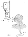
Referring now to the drawings in which like parts are
referred to by like reference numerals, an apparatus
is shown in Fig. 1 in the form of a feeding set,
indicated generally by the numeral 20, connecting the outlet
21 of the hanging supply container 22 to the nasogastric
feeding tube 23 that extends through a nasal passage 24 of
the patient and down the esophagus 25 to the stomach 26.
The feeding set here consists of a formulation chamber 27,
in the form of a drip chamber that serves also as a contact
or formulation chamber, and fluid communication means
indicated generally by the numeral 28.
"Fluid communication means" is to be understood to
include all components of fluid communication utilized in
series from the drip chamber outlet 29 to the connection 30
to the feeding tube, such as the nasogastric feeding tube
23. Components include not only portions of flexible tubing
54 but also any additional drip chambers or other
formulation chambers connected in series as seen in Figs. 16
and 19 for series flow, or in parallel but soon joined into
a single stream as seen in Fig. 20, for flow of the liquid
enteral nutritional product to the feeding tube of the
patient. The components may also include any special tubing
portions needed for utilization of a pump, and, connector
elements, respectively, between all the other components,
such as connector elements 31 or adapters 30.
It may be helpful to utilize two formulation chambers
in tandem, such as drip chambers 27 and 73 as seen in Fig.
19, to introduce a greater concentration or amount of a
given ingredient. The formulation chambers may be used in
tandem also to introduce different respective beneficial
ingredients that are not supplied together within the same
controlled release dosage form unit or particle. The
respective ingredients may constitute a little-used
combination, for example, or they may not be compatible in
storage together within a controlled release reservoir.
Two formulation chambers are shown in use sequentially
in series in the feeding set of Fig. 16 wherein the second
formulation chamber 76 is attached at the end of the
flexible tubing 54 which is distal from the supply
container. This may be found useful for adding a special
beneficial ingredient to a feeding set already made up.
With the formulation chamber 76 at the end of the set which
is distal from the supply container, it will most likely be
positioned horizontally as depicted, and is preferably made
with a bulbous mid-portion 77 or a low lying longitudinal
channel portion wherein the beneficial agent 32 in
controlled release dosage form will lie at the lower side of
the formulation chamber and be wetted by the flowing liquid
enteral nutritional product. If the beneficial agent is not
in controlled dosage form it will likewise lie, for example,
at the lower side of the bulbous section 77 until dispersed.
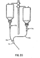
Dual formulation chambers 74 may be used in parallel
as indicated in Fig. 20, and for the same reason as the
tandem chambers, or, it may be simpler wherein it is desired
to feed one beneficial agent on a bolus basis and another on
a sustained basis. It is preferable to hang such chambers
from respective supply containers, as shown, to avoid
problems of control in order to get adequate flow through
both formulation chambers from a single supply container,
which would preferably require the use of a splitter valve
to apportion intake flow between the two parallel routes.
The outlets of each formulation chamber shown in Fig. 20 are
connected to segments of flexible tubing 54 that lead to a
"Y" fitting 75 in which the streams of liquid enteral
nutritional product are joined.
Referring again to Fig. 1, the formulation chamber 27
has positioned therein a controlled release dosage form unit
32 containing at least a physiologically effective or
diagnostically detectable amount of at least one beneficial
ingredient that is dispersible in the medium of the liquid
enteral nutritional product 33 flowing from the supply
container 22 into the formulation chamber 27 where the
liquid enteral nutritional product, which is normally water-based,
contacts the controlled release dosage form unit 32,
wetting it or immersing it within the formulation chamber
27, causing the release or discharge into the nutritional
composition of the dispersible beneficial ingredient or
ingredients, in addition to marker dye if included, stored
in the reservoir. The flow of liquid enteral nutritional
product is conveniently started or shut off or sometimes
regulated by the use of a conventional adjustable
compression clip 34.
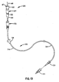
Turning now to Fig. 2, a hanging supply container 22
is shown supplying liquid enteral nutritional product 33 to
a formulation chamber 27 from which the liquid enteral
nutritional product flows through flexible tubing 54 of the
feeding set 20 a to the gastrostomy feeding tube 24a. The
gastrostomy feeding tube shown in Fig. 3 is merely exemplary
of the large variety of gastrostomy feeding tubes which are
commercially available, it being understood that the
apparatus of the present invention is usable with a variety
of gastrostomy feeding tubes.
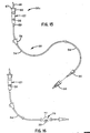
In Fig. 3 there is shown a feeding arrangement for a
jejunostomy much like the apparatus in Fig. 1, except that
the feeding set 20b is adapted to be used with a pump 35
which provides positive flow into a feeding tube 23b leading
to the small bowel 26a of the patient, whereas in a number
of cases gravity flow is utilized. Also, a second
formulation chamber 27a is employed as part of the feeding
set 20b in order to add additional or different beneficial
agent and/or marker dye, each dispersible in the medium of
the liquid enteral nutritional product 33 flowing from the
supply container 22 to formulation chamber 27 and thence
through the rest of the communication means 28b and
formulation chamber 27a of feeding set 20b to the
jejunostomy feeding tube 23b. The additional beneficial
agent may be in controlled or non-controlled dosage form.
If desired, or needed, as often is the case when
feeding via a feeding tube, such as a jejunostomy tube, a
pump, such as a peristaltic pump with cam action acting upon
the flexible tube portion 54 of the communication means 28,
or a positive displacement pump with a disposable fluid
infusion pumping chamber cassette such as that described in
U.S. Patent 4,927,411, and connected in series in the
communication means, may be used to flow or help flow the
modified liquid enteral nutritional product into the feeding
tube, for example, when it is not convenient to hang or
otherwise locate the supply container in an elevated
position relative to the patient, or, when the nutritional
product is rather viscous and flows slowly by gravity flow.
The fluid communication means 28 of the apparatus utilized
will ordinarily include a flexible tubing portion 54
connectable to or usable with a conventional pump. If the
pump employed, for example, is a peristaltic pump that
requires especially shaped flexible tubing, such tubing may
be substituted for all or a part of the communication means
delivering modified nutritional product from the formulation
chamber to the feeding tube of the patient.
The end of the flexible tubing 54 connected to the
inlet end of second formulation chamber 27a is preferably
provided with a coupling element 30 such as that shown in
the feeding set in Fig. 15, while the inlet end of the
formulation chamber is shaped complementarily to receive the
coupling element, and the
outlet of the formulation chamber communicates with a short
length of flexible tubing which likewise terminates in a
coupling element 30, that is connected to the feeding tube
23b. It may be seen that it is convenient to add the second
formulation chamber 27a, when the need arises, without
having to disconnect the parts of the feeding set. Here, for
example, the flexible tubing 54 would have to be
disconnected from the drip chamber 27 to add the formulation
chamber 27a directly in tandem at that end of the set.
The formulation chamber 27 has been loaded with a
beneficial agent in controlled release dosage form 32, while
the second formulation chamber 27a has been provided with
the same or a different beneficial agent not in controlled
release dosage form. The use of beneficial agent not in
controlled release dosage form is illustrated also in Fig.
14 where a plurality of sustained release dosage form units
32 containing beneficial agent(s) are supported above the
pierced plate 53 along with beneficial agent not in
controlled release dosage form as particles or dispersible
tablets 80.
The formulation chamber 27a may be hung vertically,
like a conventional drip chamber, but will probably be more
conveniently positioned with the direction of flow of the
liquid enteral nutritional product therethrough
approximately horizontal. Consequently, the formulation
chamber 27a should be provided with means to guide or
channel the liquid nutritional product to physically contact
the controlled release dosage form unit or units therein.
Such means may be a low lying longitudinal channel in the
body wall or a bulbous enlargement of the chamber body of
the sort illustrated in Fig. 16 or even a simple lateral
depression in the sidewall of the lower side of the chamber,
or, a trap, or weir, or any other means to retain the dosage
form units where there will be an adequate flow or depth of
liquid sufficient to afford good contact with the controlled
release dosage form units or particles located in such guide
or channel means. As seen in Fig. 16, a feeding kit has
been provided with a second formulation chamber 76 with a
bulbous body portion 77 in which a controlled release dosage
form unit 32 is positioned so that flow of liquid enteral
nutritional product will steadily contact the controlled
release dosage form unit 32 and take up beneficial agent
therefrom.
In the enlarged fragmentary view in Fig. 4, a
controlled release dosage form unit 32a in the form of an
osmotic device capsule is seen immersed in a liquid enteral
nutritional composition 33 within the drip chamber 27. This
kind of controlled release dosage form unit 32a, which has
an outer coating or membrane that does not disintegrate
readily, should have, preferably, a geometric shape, for
example, that of a rectangular solid, that will avoid
blocking flow of liquid enteral nutritional product 33
through a circular opening such as that of the channel 40
serving as the outlet of the lower part 39 of the drip
chamber 27, or, other means such as a mesh sleeve may be
employed to prevent such blockage.
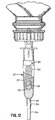
The details of construction of one example of a
conventional drip chamber suitable for use as a formulation
chamber according to the invention are illustrated in Figs.
5 and 6 which are greatly enlarged perspective views. The
drip chamber 27 as shown has two parts. The first part is a
hollow, nearly cylindrical chamber body 37 with an open
first end 38, which is the upper end when the drip chamber
is in its normal operative position, and a second end 39,
opposite the first end, that tapers or narrows down to form
an orifice 40 leading to an integrally formed outlet tube
portion 29. The chamber body 37 is preferably formed of a
clear material, such as plastic or glass, to allow see-through
visibility of the flow of the nutritional product.
Usually the drip chamber is formed of a clear, somewhat
flexible, autoclaveable plastic, such as a clear
polyvinylchloride or polyolefin resin.
The second part of the drip chamber 27 shown is in the
nature of a plug 42 with a cylindrical body that has an
inward end portion 43 that snugly press fits into the inlet
end 38 of the chamber body 37. Preferably the end portion
43 of the plug body 37 that extends into the chamber body
has a slightly reduced diameter. The edge 44, of this end
portion 43, remote from the end face of the plug is raised
slightly, being a little larger in diameter, and serves as a
stop when assembling the chamber body and the plug together.
The plug body is provided with an integrally formed fluid
communication passage 45 which may take the form of an axial
borehole in a solid plug body that communicates with an
inlet tube portion 46 that projects outwardly in the axial
direction from a collar-like flange 47 that extends radially
from the top end 48 of the plug body. But, preferably, in
order to provide a plug body, with more resiliency for
easier insertion into the upper end 38 of the chamber body
37, the fluid communication passage 45 is a concentric tube
axially located within and about as long as the plug body.
The concentric tube 45 is integrally formed with or
otherwise operatively connected to the inlet tube portion
46. A short, peripheral, integrally formed flange 50 that
extends longitudinally from the collar-like flange 47 along
a side of the plug body may be provided, if desired, to aid
in gripping the plug body when assembling the drip chamber.
The plug may be molded of a plastic such as a
polyvinylchloride resin, which may be pigmented, if desired,
for visibility as an aid to observe proper seating in the
chamber body.
The distal or free end 49 of the inlet tube portion 46
has a sufficiently sharp beveled end to facilitate
puncturing the seal (not shown) in the closure 21 in the
neck of a conventional hanging supply container, such as
supply container 22. The collar-like flange 47 serves as a
stop to the insertion of the pointed inlet tube portion 46
into the closure 21 at the neck of the supply container 22.
Other modes of construction of the formulation chamber
may be employed so long as a suitable connection to the
supply container is provided as well as a see-through
tubular portion wherein the rate of flow of the liquid
enteral nutritional product may be observed. For example,
see the formulation chamber 82 depicted in Figs. 17 and 18
wherein the plug end 83 of the formulation chamber is
integrally formed with the closure 84 for a conventional
supply container to be threadably connected thereto. The
apparatus of the invention is not to be considered limited
to the inclusion of any of the drip chambers here used by
way of illustration, nor is the method limited to the use
thereof.
The drip chamber shown in Figs. 5 and 6 has a
controlled release dosage form unit 32 disposed therein
ready for use. The controlled release dosage form unit will
be preselected according to the contents thereof to provide
the additional nutrient(s) and/or medicament(s) and/or
probiotic(s) and/or diagnostic agent(s) and/or other
beneficial ingredient(s) selected by the care giver in
charge, along with a marker dye, if desired. As used herein
and in the claims, medicaments are understood to be
substances used in therapy. The formulation chamber, or
chambers, selected may contain more than one controlled
release reservoir in order to provide a combination of
nutrients, or, a combination, such as nutrients and
medicaments or other beneficial agents, tailored to the
needs of the patient being fed. The formulation chamber may
also be one provided with the same or different beneficial
agent or agents both in controlled and not-controlled
release dosage form in order to provide, for example, a
greater amount, as in the case of a nutrient. A non-controlled
dosage form of a beneficial agent may be used to
supply the beneficial agent over a shorter period of time,
as might be desired with a medicament.
The controlled release dosage form units employed will
preferably be in the form of a coated tablet, an osmotic
delivery device, a coated capsule, a microencapsulated
microsphere, an agglomerated particle, e.g., as of molecular
sieving type particles, or, a fine hollow permeable fiber
bundle, or chopped hollow permeable fibers, agglomerated or
held in a fibrous packet. To avoid having a dosage form unit
or particle block the flow of the liquid enteral nutritional
composition through the outlet orifice 40 of the drip
chamber, if the dosage form unit is one that maintains
integrity of the exterior layer or coating thereof while the
ingredients leach out or are expressed out during contact
with the liquid enteral nutritional product, it is preferred
that the dosage form unit have a geometric shape, e.g., a
rectangular solid, or a star shape, either of which will not
fully block a round passageway. If a different type of
controlled release dosage form is used which dissolves or
disintegrates so the interim shape is not controllable, or
if it leaves an insoluble skeletal structure or debris, it
is preferred to confine the controlled release dosage form
units in a mesh-like bag within the drip chamber or other
formulation chamber such as the mesh sleeve 51 shown in Fig.
11. In Fig. 11 there is also shown a plurality of
controlled release dosage form units which may be employed
in order to provide additional beneficial ingredients that
are dispersible in the medium of the liquid enteral
nutritional product in order to obtain a tailor-made
nutrient composition for the patient. This may be
especially helpful wherein none of the controlled release
dosage forms at hand may have the exact combination of
ingredients that is desired or needed for a patient, and the
combination can be made up a 1a carte if there are at hand
controlled release dosage form units containing the various
ingredient contents desired.
As seen is Fig. 12, a foraminous sleeve, or bag, that
is, one with numerous holes in it, may be used to position
the controlled release reservoir(s) in the drip chamber or
other formulation chamber.
Or, turning now to Fig. 13, a plastic or ceramic or
corrosion resistant metal plate 53 that is foraminous or
pierced may be placed within the body of the lower part of
the drip chamber 37, or other formulation chamber, to
support the controlled release dosage form units, in this
case, a very large number where the desired ingredient is
needed in relatively large amount. If desired, the
foraminous plate 53 may be replaced by a grid or screen 41,
such as that shown in Fig. 13A and is also preferably formed
of a plastic or vitrified ceramic or corrosion resistant
metal, such as stainless steel.
The foregoing means of disposing, i.e., supporting, the
controlled release dosage form units within the drip chamber
may also be used in any additional formulation chambers in
the feeding set employed.
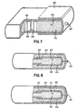
The controlled release dosage form unit depicted in
Fig. 7 is of the osmotic pump type that functions in the
manner of the osmotically driven delivery device described
and claimed in U.S. Patent 5,318,558, the specification and
drawings of which are incorporated herein by reference with
respect to the structure of the controlled release dosage
form units therein described and the method of making them
and their mode of functioning, albeit here with different
environments and contents and end uses. In the pump type
controlled release dosage form units, or delivery devices,
the beneficial ingredient(s) in liquid form, i.e., either in
the liquid state or in solution in a suitable solvent, is
expressed out from a cylindrical enclosure or cavity 56
within the reservoir through a small orifice 57 by the
action of a piston 58 driven by pressure developed by
osmotic infusion of moisture through a semi-permeable
membrane 59 confining a hydro-active substance 60 behind the
piston 58, driving the piston steadily toward the side of
the reservoir where the ingredient(s) 61 is forced out
through the orifice 57. Orifice 57 is a very small and is
preferably drilled by a laser beam. The cylindrical
enclosure 56 is formed within an outer non-permeable
membrane or coating 62. The hydro-active substance 60 may
be a water-soluble salt like magnesium sulfate, magnesium
chloride, potassium sulfate, sodium chloride, sorbitol,
inositol, urea, or a saccharide such as glucose or fructose
or dextran, or, a hydrophilic polymer such as a
poly(hydroxyalkyl methacrylate) with a molecular weight of
30,000 to 5,000,000, or a poly (vinylpyrrolidine) with a
molecular weight of 10,000 to 360,000, an anionic or
cationic hydrogel or polyvinyl alcohol having low acetate
residual.
The controlled release reservoir depicted in Fig. 8 is
another osmotic dosage system with a sustained release
dosage form that functions in the manner of the osmotically
operated delivery device described and claimed in U.S.
Patent 5,324,280, the specification and drawings of which
are hereby incorporated herein by reference with respect to
the structure of the sustained release dosage form units
there described and the method of making them and their mode
of functioning, albeit here with different environments and
contents and end uses. In this type of system, the
beneficial ingredient(s) 63 to be fed in liquid state or
solution form, is enclosed within a non-permeable coating 64
that is surrounded by a layer 65 of hydro-active material
that is entirely confined within an outer semi-permeable
membrane coating 66. Osmotic pressure developing in the
hydro-active coating 66. Osmotic pressure developing in the
hydro-active layer 65 upon infusion of moisture thereinto
compresses the core 67 containing the liquid form beneficial
ingredient(s) 63 and forces that liquid out steadily through
a very small passageway 68 from the core 67 to the exterior
of the reservoir.
Turning now to Fig. 8A, the controlled release dosage
form unit as shown in either of Figs. 7 and 8 may be coated
with a readily soluble coating, such as coating 69, which
may be a coating of marker dye or beneficial agent for the
purpose of getting a quick initial release of such dye or
beneficial agent. In the case of a beneficial agent such as
a medicament, this may be desirable in order to get a blood
content level up quickly, after which a steady sustained
release level may be needed.
The controlled release reservoir 70 depicted in Fig. 9
is of the type in which there is provided, within a carrier
envelope 71 that is very quickly soluble or disintegrable in
the medium of the liquid enteral nutritional product, a
quantity of microcapsules or molecular sieving type
particles 72. If microcapsules, the particles 72 are
microspheres each individually coated and each containing
the same beneficial ingredient or mixture thereof, with a
plurality of distinct numerical portions or fractions
thereof each provided with a coating that dissolves or
disintegrates in or is permeated by the medium of the liquid
enteral nutritional product. The various numerical
fractions, respectively, each have a coating of a different
thickness whereby upon making a blend of the microcapsules
with a fraction that is uncoated, the mixture shows a
sustained release effect when exposed to an aqueous medium,
such as the medium of a liquid enteral nutritional product.
The envelope and coatings must essentially be acceptable for
nutritional feeding, or disintegrable, i.e., suspendable,
but not necessarily soluble.
If the particles 72 are of a molecular sieving type, or
a mixture of two or more molecular sieving grades, the
particles have been impregnated with a beneficial ingredient
or ingredients to be supplied during feeding and the
particles agglomerated into desired size granules or clumps
that are unable with or without being coated, to form a
controlled release dosage form usable according to the
invention, the coating, if applied, being soluble, or
disintegrable, i.e., suspendable, in or permeable to the
medium of the liquid enteral nutritional product to be
modified. The molecular sieving type material has a porous
structure with non-aligned pores where pore size is
critically controlled in manufacture in order to create the
property of holding molecules of different size
characteristics or molecular weights in a selective manner.
The holding or storing properties impart sustained release
behavior.
The carrier for controlled release dosage form units
may also take the form shown in Fig. 9 but containing a
fibrous material in which the fibers are hollow and
permeable and slowly release substances such as the
beneficial ingredients herein added to a nutritional
product. A measured quantity of such fibers, in a coil or
in a chopped form, may be used in a retaining means such as
a sleeve or bag, or agglomerated with a binder, or coated
with a dispersible, disintegrable or permeable coating.
Such fibers, which may be formed primarily of a cellulose
ether or ester, are capable of storing up and subsequently
yielding up a beneficial ingredient or mixture of
ingredients, upon contact with flowing liquid enteral
nutritional product within the drip chamber or other
formulation chamber.
The fibrous and highly porous tea bag-type of carrier
envelope 79 shown in Fig. 9A may also be used to hold or
support, within a formulation chamber, a quantity of
microencapsulated microspheres, or a quantity of molecular
sieving type material or, for example, a quantity of chopped
fine hollow permeable fibers 78, any of which forms holding
or containing a dosage amount of one or more beneficial
agents. Such tea bag-type of envelope, or a plurality
thereof, may also be used to position within a formulation
chamber any combination of: (1) one or more beneficial
agents in controlled release dosage form; (2) one or more
beneficial agents in controlled dosages form along with one
or more beneficial agents not in controlled dosage form,
wherein the beneficial agents not in controlled dosage form
may be the same or different agents than those present in
controlled dosage form; and (3) a marker dye or dye mixture
in combination with either (1) or (2) and in a controlled
release dosage form setting, as well as in any external
coatings of controlled release dosage form units. Wherein
more than one formulation chamber is used, the additional
formulation chamber may have positioned therein, e.g., a
fibrous carrier bag having therein only non-controlled
beneficial agent along with or without marker dye.
Any mode of making a sustained or controlled release
storage coating, envelope or binder may be used in making a
controlled release dosage form unit usable according to the
invention so long as the soluble, dispersible or
disintegrable components of the dosage form units used are
physiologically acceptable and the controlled release dosage
form unit is capable of storing one or more beneficial
ingredients as above defined until use and releasing the
same into a liquid enteral nutritional product at a useful
rate or manner and/or over a useful period of time of at
least one-half hour and preferably over at least two hours
during enteral feeding, or longer if needed for certain
medicaments and nutrients. Tablets and capsules and other
dosage forms may generally be coated with well known
materials that slow down and delay the solubilization or
suspension of the beneficial agent, materials such as zein,
shellac, methacrylate polymers and copolymers, and cellulose
ethers and esters that are frequently used for the purpose.
Such materials are described in U.S. Patent 5,160,742 and
are generally adaptable for the present purpose, although
the coated articles described in the patent are used in a
different manner.
Wherein it is necessary or quite important to provide a
beneficial ingredient, or a mixture of ingredients, as
herein defined, for example, one or more medicaments,
according to the invention and at a fairly uniform rate over
time, with preferably not more than about a 25% variation
above or below the median rate over a period of two to about
24 hours or more, the osmotic pump and other osmotic
delivery systems are to be preferred. Generally, a wide
range of rates is usable as long as at least an effective
amount is supplied without reaching excessive amounts.
Amongst the beneficial agents that are most likely to
be added to conventional enteral nutritional compositions
are, for example, nutrients, such as, glutamine, arginine,
fermentable dietary fibers, non-fermentable dietary fibers,
enzymes such as lipases, combinations of amino acids,
oligosaccharides such as fructo-oligosaccharides, vitamins,
short chain (C3 -C4) fatty acids, pyruvate precursors the
form of pyruvamide, or pyruvyl-amino acids, such as,
pyruvyl-glycine, pyruvyl-alanine, pyruvyl-leucine, pyruvylvaline,
pyruvyl-sarcosamine and their amides, esters and
salts, structured lipids, d-cyroinositol, lactoferrin,
marine oils and acidulents such as ascorbic acid. An
example of a structured lipid which provides excellent
nutritional support is a glycerol backbone with at least one
gamma linolenic acid or dihomogamma-linolenic acid residue
in combination with a medium chain (C5 -C22) fatty acid
residue and a C18-C22 n-3 fatty acid residue selected from
alpha-linolenic and stearodonic, eicosapentaenoic and
docosahexaenoic acid.
Medicaments that may usefully administered in this
manner include, for example, antihistamine drugs; anti-infective
agents, such as antibiotics, antivirals and
urinary tract anti-infectives; antineoplastic agents;
autonomic drugs such as adrenergic agents and skeletal
muscle relaxants; blood formation and coagulation drugs;
cardiovascular drugs; central nervous system agents;
diagnostic agents; electrolytic, caloric and water balance
agents; enzymes; antitussive, expectorant and mucolytic
agents; gastrointestinal drugs such as antacids; gold
compounds; hormones and synthetic substitutes; smooth muscle
relaxants; and unclassified therapeutic agents. Other
examples are H2 blockers like Tagamet®, prokinetic
medication, bioactive peptides, medication for diabetic
condition, chemotherapy agents, or any medication intended
for oral administration that will not react adversely with
the nutritional formulation being fed into the
gastrointestinal tract.
Probiotics that may be usefully administered in this
manner include, for example, Lactobacillus acidophilus GG,
as described in U.S. Patent 4,839,281, Lactobacillus
reuteri, Lactobacillus animalis, and Lactobacillus
salivarius, as described in WO 93/02558. Probiotics are
live microorganisms that aid in the digestion of food or
that help control the population of harmful microorganisms
in the intestines.
If desired, a physiologically acceptable marker dye or
dye mixture may be provided in the formulation chamber or
chambers or chambers in addition to one or more of the
beneficial ingredients above disclosed in order that the
flow of modified liquid nutritional product may be made
visible as an aid to the caregiver. This may be done by
placing in the formulation chamber one or more sustained
release dosage form units containing both the dye or dye
mixture and the beneficial ingredient(s), if such dosage
form units are available. Or, a controlled release dosage
form unit containing the dye or dye mixture and a separate
controlled release dosage form unit containing the
beneficial ingredients(s) may be placed together in the
formulation chamber. As indicated above, in order to impart
prompt visibility to the flow of modified nutritional
product as an aid to the caregiver, it may be preferred to
apply an external, readily soluble coating of the marker dye
to a controlled release dosage form unit, ordinarily one
containing marker dye. The marker dye is admixed with a
small amount of one or more conventional easily dispersible
tablet coating excipients, such as, polyvinylpyrrolidine
having an average molecular weight in the range of about
35,000 to 50,000, mannitol, magnesium stearate, and zein or
guar gum, in applying the dye to the dosage form unit during
manufacture. Generally the amount of excipients in total is
less than about 10 percent by weight of the coating. Or,
the dosage form unit may be simply dipped in a solution of
the marker dye and dried.
A marker dye or dye mixture that is useful according to
the invention is a colorant dye or a fluorescent dye or a
mixture of such dyes that is physiologically acceptable to
the patient and compatible with the beneficial agents being
fed therewith. The dye or dye mixture must also be capable
of being taken up in detectable concentration in the liquid
medium of the liquid enteral nutritional product while the
product flows through a drip chamber or other formulation
chamber having positioned therein at least one sustained
release dosage form unit containing the marker dye or dyes.
If the dye is detectable in the drip chamber, it can be
expected to be detectable, ordinarily, if it somehow reaches
the oral cavity of the patient.
The marker dye employed may be a colorant dye that
imparts color that is visible under white light, for
example, normal daylight or artificial room light
encountered in a hospital or clinic, or, the marker dye may
be a fluorescing dye that fluoresces visibly under
ultraviolet light, or, a mixture of a colorant dye and a
fluorescing dye. A mixture of a colorant dye and
fluorescing dye appears to be especially advantageous in
that flow through the formulation chamber is readily
perceived under normal lighting conditions with colorant dye
present, while even a small amount of nutritional product
out of place, for example, in the oral cavity or nasal
passage, will be more easily detected with the aid of
ultraviolet light if it contains a fluorescing dye. This is
because of the nature of the fluorescing dyes that are
especially visible under ultraviolet light even when present
in very low concentration.
The dye or dye mixture used must be physiologically
acceptable. Usually food grade colorant dyes approved under
the provisions of the United States Food, Drug and Cosmetic
Act are suitable. Preferred are F.D. & C. Blue #1 and F.D.
& C. Blue #2 dyes. The dye or dye mixture used must be
soluble in the medium of the liquid enteral nutritional
product being fed and compatible with the beneficial
ingredient(s) being added during the feeding. Generally
about 0.1 milligram of dye per milliliter of liquid enteral
nutritional product is desired to give a readily visible
coloration to the nutritional product.
Wherein it is important to be able to detect
misdirected liquid enteral nutritional product, the marker
dye used may be a fluorescing dye, such as F.D. & C. Red #3,
which is highly visible at a very low concentration under
ultraviolet light and also imparts a visible coloration to
the liquid nutritional product under white light conditions.
Other suitable fluorescing dyes are: quinine, F.D. & C. Red
#22, F.D. & C. #28, fluorescein, and D 282 UV Blue available
from DaGlo of Cincinnati, Ohio and also identified as 16470-24-9
in the Chemical Abstracts System with a color index of
220 as a fluorescent brightener. As indicated above, if
desired, a mixture of colorant dye and fluorescing dye may
be used. Generally, adding to the nutritional product in
the formulation chamber about 0.01 to 0.05 mg/ml of
fluorescing dye is adequate for detectability under
ultraviolet light.
A feeding set, such as the kit 20 shown in Fig. 15, is
conveniently provided in packaged form ready for use in
feeding a liquid enteral nutritional product. The kit
includes a controlled release dosage form unit 32, a drip
chamber 27 or other formulation chamber, and liquid
communication means 28 consisting mainly of a length of
flexible tubing attached at one end to the outlet of the
drip chamber 27 and at the other end to a fitting 30 for
coupling attachment to a feeding tube. The fitting 30 is
shown with a cap 55 telescoped for purposes of illustration.
The cap is simply for protection of the fitting 30 until the
feeding set is used. The controlled release dosage form
unit 32 has already been placed in the drip chamber 27 and
contains one or more beneficial ingredients as defined
hereinabove for modification of a liquid enteral nutritional
product during feeding thereof, and additionally a marker
dye, if desired. The kit may also be provided with a
plurality of controlled release dosage form units 32 within
the drip chamber 27 if a single dosage form unit does not
contain each type of beneficial ingredient desired for
modification of the nutritional product or if it is desired
to add a marker dye and it is not present in the controlled
release dosage form units for the beneficial ingredients
selected.
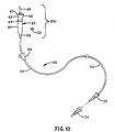
A similar kit 20c, as shown in Fig. 10, includes the
controlled release dosage form unit 32 which has not been
placed in the drip chamber 27 before shipping the kit, but
accompanies the drip chamber as part of the kit. Other kits
are prepared with various numbers and varieties of
controlled release dosage form units containing various
beneficial agent and marker dye combinations and beneficial
agents not in controlled release form, to accompany the
feeding sets.
In a preferred embodiment of the apparatus
of the type illustrated in Fig. 2, a controlled
release dosage form unit of the type illustrated in Fig. 8A
is positioned in the formulation chamber. The dosage form
unit contains glutamine and F.D. &'C. Blue #1 dye and is
coated with a layer of the same blue dye admixed with about
3 percent by weight in total of polyvinylpyrrolidine having
an average molecular weight in the range of about 35,000 to
44,500. The feeding kit is connected to a hanging supply
container of a liquid enteral nutritional product having a
viscosity of about 40 cps., such as PULMOCARE® , a product
of the Ross Products Division of Abbott Laboratories,
Columbus, Ohio, and a steady flow of the nutritional product
is commenced. The dye coating provides immediate visible
color within the drip chamber within 2 seconds and the
controlled release dosage form unit provides the blue dye in
a concentration of at least 0.075 mg/ml for a period of over
1,440 minutes during the flow of about 3,999 ml of the
liquid enteral nutritional product. The dosage form unit
also provides glutamine at a concentration of at least 1.25
mg/ml during the flow of the liquid enteral nutritional
product, commencing after about 1 ml of flow.
As above-discussed, the feeding set 20 may deliver
one or more
beneficial agents from one or more dosage form units 32
contained in one or more drip chambers. For example, in the
embodiment depicted in FIG. 3, drip
chambers 27 and 27a are each constructed such that one or
more beneficial agent dosage form units 32 can be placed
therein, thereby allowing feeding set 20 to deliver a
selected quantity of a single beneficial agent, i.e., where
both drip chambers 27 and 27a contain dosage form units
containing the same beneficial agent, and thereby allowing
feeding set 20 to deliver more than one beneficial agent at
a time, i.e., where drip chambers 27 and 27a contain dosage
form units that contain more than one beneficial agent.
FIGS. 16 and 20 depict alternative embodiments of the
present invention that are also capable of delivering
simultaneously one or more beneficial agents from one or
more dosage form units.
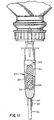
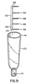
FIG. 21 depicts an embodiment of the
present invention constructed to deliver simultaneously one
or more beneficial agents to a patient. In this embodiment of the present invention,
chamber 100 having an inlet 114 and an outlet 112 is configured to
receive retainer 102 therein. Chamber 100 and retainer 102
can be constructed from a variety of materials known to be
suitable for use in enteral feeding sets. Examples of these
materials are discussed above. Chamber 100 can have a
variety of known configurations suitable for use in an in-line
enteral fluid feeding set. As depicted in FIG. 21,
chamber 100 is in the form of a drip chamber of a size
suitable to receive retainer 102 therein.
As depicted in FIG. 21, retainer 102 includes a
first support member 104 and a plurality of second support
members 106 extending from first support member 104.
Retainer 102 can be of unitary construction, e.g., a molded
plastic, or can be constructed from a plurality of members
interconnected by a variety of known methods. First
support member 104 is constructed to interconnect second
support members 106 and can have a variety of
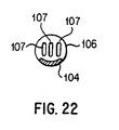
configurations. In the preferred embodiment of the present
invention depicted in FIG. 22, first support member 104 is
substantially semi-circular in cross-section. It will be
appreciated that this configuration will impair lateral
movement of dosage form units 32 placed on first support
member 104 between second support members 106. First
support member 104 can have a variety of other cross-sectional
configurations, e.g., circular and rectangular,
without departing from the scope of the present invention as
defined in the appended claims. The dimensions of first
support member 104 and second support members 106 can be
varied to receive a variety of sizes and shapes of dosage
form units 32. It also will be appreciated that a variety
of sizes and shapes of dosage form units 32 in a single
configuration of retainer 102 without varying the dimensions
of first support member 104 and/or second support members
106, provided that the dosage form units are appropriately
retained by retainer 102 within chamber 100, as described in
greater detail herein.
Second support members 106 preferably define one
or more apertures 107 therethrough, as depicted in FIG. 22,
such that a liquid enteral nutritional product flowing
through chamber 100 will pass through apertures 107.
Apertures 107 defined through second support members 106 can
vary in size, shape, spacing, and number. It will be
appreciated that the flow characteristics through second
support members 106 can be varied by varying one or more of
these parameters of apertures 107. Thus, it is possible to
control the manner in which dosage form units 32 release
beneficial agents by varying one or more of these
parameters. For example, it is possible to delay the
delivery of beneficial agent from one dosage form units 32
relative to other dosage form units 32 contained in retainer
102 by adjusting the size, shape, number, and/or spacing of
apertures 107 defined through the second support members 106
adjacent to the dosage form unit 32 so as to limit the
volume of fluid coming into contact with the dosage form
unit 32 that is to be provided in an extended release
manner. The size, shape, spacing, and number of apertures
107 thus are determined by the desired flow characteristics
through chamber 100 and retainer 102.
In the preferred embodiment of the present
invention, apertures 107 direct flow through retainer 102
such that the fluid directly contacts each of the dosage
form units 32 contained therein, thereby ensuring that
beneficial agent from each of the dosage form units 32 is
released into the fluid. However, as above-discussed, the
flow characteristics through retainer 102 can be varied in
order to delay delivery of beneficial agent from one or more
of dosage form units 32.
Second support members 106 preferably are spaced a
sufficient distance from one another such that one or more
beneficial agent dosage form units 32 can be retained
therebetween. As depicted in FIG. 21, second support
members 106 extend substantially perpendicularly from first
support member 104. However, it will be appreciated that
the angular orientation of second support members 106
relative to first support member 104 can be varied without
detrimentally affecting the efficacy of the present
invention. For example, second support members 106 can be
oriented so that they angle upwardly when retainer 102 is
held such that first support member 104 is substantially
vertical and first end 108 is positioned above second end
109, thereby urging dosage form units 32 toward first
support member 104. Second support members 106 and first
support member 104 are sized such that retainer 102 can be
placed in chamber 100.
Outlet 112 of chamber 100 preferably is
constructed such that it can be fluidly connected to an in-line
enteral fluid delivery set. First end portion 114 of
chamber 100 preferably is constructed to receive a closure
device such as plug 42 depicted in FIG. 6 and described in
detail above. The closure device preferably will be
constructed such that it can be fluidly connected to an in-line
fluid enteral fluid feeding set or directly to a source
of fluid, thereby permitting chamber 100 to be connected
fluidly to an in-line enteral nutritional product fluid
feeding set. Chamber 100 can be configured such that the
closure device, e.g., plug 42, can be secured thereto,
thereby preventing the inadvertent opening of chamber 100
during use. In a preferred embodiment of the present
invention, the chamber 100 is configured to receive the
closure device, e.g., plug 42, by a snap fit which both
secures the closure device to chamber 100 and minimizes the
possibility of tampering with retainer 102, and the dosage
form units 32 retained therein, after retainer 102 has been
placed in chamber 100.
When retainer 102 is placed on a flat surface such
that first support member 104 is horizontal and second
support members 106 extend upwardly therefrom, dosage form
units 32 can be loaded into retainer 102 by placing them on
first support member 104 between second support members 106.
This process can be conducted at any time prior to delivery
of enteral nutritional product to a patient. For example,
dosage form units 32 containing selected beneficial agents
can be loaded in retainer 102 and chamber 100 by a
manufacturer or supplier and thereafter distributed to end
users. Alternatively, dosage form units 32 can be loaded in
retainer 102 and chamber 100 in a pharmacy prior to delivery
to a patient. Further, dosage form units 32 can be loaded
in retainer 102 and chamber by a medical professional or by
a patient prior to connecting chamber 100 fluidly to an
enteral feeding system. The number and type of dosage form
units, and the beneficial agents contained therein, can be
varied from patient-to-patient, thereby allowing significant
variation in the amount and type of beneficial agents
delivered to the patient with the enteral nutritional
product. In addition, some of the dosage form units 32 can
be in a sustained-.release form while others are not in a
sustained-release form, thereby allowing for the selection
of a staged delivery plan of the beneficial agents contained
in retainer 102. Thus it should be apparent that this
embodiment of the present invention affords a great
opportunity to design and deliver a variety of beneficial
agents to a patient with an enteral nutritional product in
accordance with the individual patient's needs as well as
the needs of medical professionals trying to treat the
patient and/or diagnose the patient's condition.
Retainer 102 can be constructed such that it does
not rock when placed on a flat surface in the above-discussed
manner. For example, when first support member
104 is semi-circular in cross-section, as depicted in FIG.
22, a surface of first support member 104, or of retainer
102, can be rendered substantially flat, thereby preventing
the rocking of retainer 102 during loading thereof. In the
alternative, first support member 104 can be provided with
stops which prevent retainer 102 from rocking during loading
thereof. One of ordinary skill in the art will appreciate
that other methods for preventing the rocking of retainer
102 are possible.
Chamber 100 can be constructed of a material that
is substantially transparent, thereby allowing a medical
professional to determine visually the contents of chamber
100 while it is in use. Such a visual determination will be
facilitated if the various beneficial agents and dosage form
units present in retainer 102 have distinguishing shapes,
sizes, and/or colors. Chamber 100 can be constructed of a
translucent or opaque material without departing from the
scope of the present invention.
Although retainer 102 is depicted in FIG. 21 as
including four second support members 106, it will be
appreciated that retainer 102 can be constructed such that
it includes one or more second support members 106 without
departing from the scope of the present invention set forth
in the appended claims.
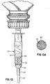
In an alternative embodiment depicted in FIG. 24,
retainer 102 includes cover 110 which is constructed to
retain dosage form units 32 in retainer 102. In the
embodiment depicted in FIG. 24, cover 110 is hingedly
attached to first support member 104 along a portion
thereof. However, it will be appreciated that cover 110 can
be a separate element from first support member 104 without
departing from the scope of the present invention. Cover
110 includes an outer wall 112 which, in the depicted
embodiment, is constructed such that outer wall 112 and
first support member 104 encircle a periphery of a dosage
form unit 32 contained in retainer 102 when cover 110 is in
a closed position relative to retainer 102. In this
embodiment, cover 110 also has an open position relative to
retainer 102 in which dosage form units 32 can be placed
readily between second support members 106.
It will be appreciated that cover 110 and first
support member 104 need not completely encircle the
periphery of dosage form unit 32 to retain dosage form units
32 in retainer 102. For example, one or more apertures can
be formed through cover 110. Such apertures can be varied
in size, shape, location, and number in order to create the
desired flow characteristics through retainer 102 and
chamber 100. In addition, cover 110 and first support
member 104 can be constructed such that one or more gaps are
present therebetween when cover 110 is in its closed
position. Here again, the flow characteristics through
retainer 102 and chamber 100 can be varied by changing the
size, shape, location, and number of such gaps.
In the embodiment depicted in FIG. 24, cover 110
further includes support walls 114. Support walls 114
extend from outer wall 112 and are constructed to interact
with second support members 106 in order to retain dosage
form units 32 and in order to permit flow through second
support members 106 and support walls 114. In the depicted
embodiment, second support members 106 and support walls 114
are substantially identical in construction and define semi-circular
apertures therethrough. When placed in contact
with one another by hingedly closing cover 110 in the
embodiment of the invention depicted in FIG. 24, respective
sets of second support members 106 and support walls 114
define lateral support members capable of retaining a dosage
form unit 32 therein. A single circular aperture is defined
through each of the lateral support members thus formed,
thereby facilitating flow through retainer 102. As above-discussed,
the size, shape, number, and position of the
apertures thus formed can be varied dependent upon the
desired flow characteristics through retainer 102.
Variation of these parameters can be achieved by varying the
size, shape, number, and position of apertures defined
through second support members 106 and/or support walls 114.
A locking mechanism 116 of known construction can
be provided in order to prevent the premature opening of
retainer 102 after cover 110 has been closed. In the
depicted embodiment, locking mechanism 116 includes a pair
of pins 118 positioned on outer wall 112 of cover 110 and a
pair of complementary holes 120 formed in first support
member 104. Holes 120 and pins 118 are constructed such
that pins 118 are frictionally retained in holes 120 when
cover 110 is moved to its closed position, thereby
preventing unwanted opening of retainer 102. In the
embodiment of the present invention in which cover 110 is
hingedly mounted on first support member 104, one or more
pairs of complementary pins 118 and holes 120 positioned as
depicted in FIG. 24 will provide the desired locking effect.
If cover 110 is a separate element rather than being
hingedly connected to first support member 104, additional
pairs of complementary pins 118 and holes 120 can be
positioned on cover 110 and first support member 104 to
provide the desired locking effect therebetween. It will be
appreciated that additional locking mechanisms 116 of known
construction can be used in connection with retainer 102 of
the present invention.
FIG. 12 depicts an apparatus
in which foraminous sleeve or bag 52 is provided
in drip chamber 27. FIG. 9A depicts
a carrier envelope 79
that can be placed in a drip chamber 27. Foraminous
sleeve 52 and carrier envelope 79 can be constructed such
that one or more beneficial agents can be placed therein.
In this way, one or more beneficial agents can be placed in
foraminous sleeve 52 or carrier envelope 79 in order to
alter the characteristics of an enteral nutritional product
that is delivered through a fluid delivery system in which
the foraminous sleeve 52 and/or carrier envelope 79 is
present. It will be appreciated that the beneficial agent
thus provided can be in the form of a dosage form unit 32,
or can be in a powder, granular, gel, or other form,
dependent upon the characteristics of the beneficial agent
and the manner in which the beneficial agent is to be
delivered to a patient, e.g., in a bolus or in an extended
release delivery profile. The amount of the beneficial
agent can be varied by additional quantities of the
beneficial agent in the foraminous sleeve 52 and/or the
carrier envelope 79. Further, the number of beneficial
agents thus delivered can be varied by placing more than one
beneficial agent in the foraminous sleeve 52 and/or the
carrier envelope 79. Thus, these embodiments of the present
invention allow the system and method of the present
invention to be adapted to the particular medical and
diagnostic needs of the patient to whom an enteral
nutritional product is to be delivered.