EP1056378B1 - Beverage brewing device having an integral beverage server locking apparatus - Google Patents
Beverage brewing device having an integral beverage server locking apparatus Download PDFInfo
- Publication number
- EP1056378B1 EP1056378B1 EP99908161A EP99908161A EP1056378B1 EP 1056378 B1 EP1056378 B1 EP 1056378B1 EP 99908161 A EP99908161 A EP 99908161A EP 99908161 A EP99908161 A EP 99908161A EP 1056378 B1 EP1056378 B1 EP 1056378B1
- Authority
- EP
- European Patent Office
- Prior art keywords
- brew cup
- linkage
- brewing device
- beverage
- beverage brewing
- Prior art date
- Legal status (The legal status is an assumption and is not a legal conclusion. Google has not performed a legal analysis and makes no representation as to the accuracy of the status listed.)
- Expired - Lifetime
Links
- 235000013361 beverage Nutrition 0.000 title claims description 100
- 230000007246 mechanism Effects 0.000 claims description 31
- 230000002093 peripheral effect Effects 0.000 claims description 5
- XLYOFNOQVPJJNP-UHFFFAOYSA-N water Substances O XLYOFNOQVPJJNP-UHFFFAOYSA-N 0.000 description 26
- 235000013353 coffee beverage Nutrition 0.000 description 14
- 238000010438 heat treatment Methods 0.000 description 9
- 239000007788 liquid Substances 0.000 description 8
- 238000012360 testing method Methods 0.000 description 5
- 230000009471 action Effects 0.000 description 4
- 238000013461 design Methods 0.000 description 4
- 238000002405 diagnostic procedure Methods 0.000 description 3
- 230000006870 function Effects 0.000 description 3
- 230000003287 optical effect Effects 0.000 description 3
- 238000013459 approach Methods 0.000 description 2
- 230000006854 communication Effects 0.000 description 2
- 238000004891 communication Methods 0.000 description 2
- 238000001816 cooling Methods 0.000 description 2
- 230000007812 deficiency Effects 0.000 description 2
- 230000000881 depressing effect Effects 0.000 description 2
- 238000010586 diagram Methods 0.000 description 2
- 238000001802 infusion Methods 0.000 description 2
- 230000000977 initiatory effect Effects 0.000 description 2
- 229910052751 metal Inorganic materials 0.000 description 2
- 239000002184 metal Substances 0.000 description 2
- 238000012544 monitoring process Methods 0.000 description 2
- 238000012546 transfer Methods 0.000 description 2
- 229910052782 aluminium Inorganic materials 0.000 description 1
- XAGFODPZIPBFFR-UHFFFAOYSA-N aluminium Chemical compound [Al] XAGFODPZIPBFFR-UHFFFAOYSA-N 0.000 description 1
- 230000008901 benefit Effects 0.000 description 1
- 230000007175 bidirectional communication Effects 0.000 description 1
- 239000004020 conductor Substances 0.000 description 1
- 230000009977 dual effect Effects 0.000 description 1
- 238000005485 electric heating Methods 0.000 description 1
- 230000005669 field effect Effects 0.000 description 1
- 239000008236 heating water Substances 0.000 description 1
- 235000021539 instant coffee Nutrition 0.000 description 1
- 238000012423 maintenance Methods 0.000 description 1
- 239000000463 material Substances 0.000 description 1
- 229910044991 metal oxide Inorganic materials 0.000 description 1
- 150000004706 metal oxides Chemical class 0.000 description 1
- 238000000034 method Methods 0.000 description 1
- 239000010970 precious metal Substances 0.000 description 1
- 238000003825 pressing Methods 0.000 description 1
- 230000008439 repair process Effects 0.000 description 1
- 239000004065 semiconductor Substances 0.000 description 1
- 229910001220 stainless steel Inorganic materials 0.000 description 1
- 239000010935 stainless steel Substances 0.000 description 1
Images





Classifications
-
- A—HUMAN NECESSITIES
- A47—FURNITURE; DOMESTIC ARTICLES OR APPLIANCES; COFFEE MILLS; SPICE MILLS; SUCTION CLEANERS IN GENERAL
- A47J—KITCHEN EQUIPMENT; COFFEE MILLS; SPICE MILLS; APPARATUS FOR MAKING BEVERAGES
- A47J31/00—Apparatus for making beverages
- A47J31/44—Parts or details or accessories of beverage-making apparatus
- A47J31/4403—Constructional details
- A47J31/446—Filter holding means; Attachment of filters to beverage-making apparatus
-
- A—HUMAN NECESSITIES
- A47—FURNITURE; DOMESTIC ARTICLES OR APPLIANCES; COFFEE MILLS; SPICE MILLS; SUCTION CLEANERS IN GENERAL
- A47J—KITCHEN EQUIPMENT; COFFEE MILLS; SPICE MILLS; APPARATUS FOR MAKING BEVERAGES
- A47J31/00—Apparatus for making beverages
- A47J31/44—Parts or details or accessories of beverage-making apparatus
- A47J31/4403—Constructional details
- A47J31/441—Warming devices or supports for beverage containers
- A47J31/4425—Supports for beverage containers when filled or while being filled
-
- A—HUMAN NECESSITIES
- A47—FURNITURE; DOMESTIC ARTICLES OR APPLIANCES; COFFEE MILLS; SPICE MILLS; SUCTION CLEANERS IN GENERAL
- A47J—KITCHEN EQUIPMENT; COFFEE MILLS; SPICE MILLS; APPARATUS FOR MAKING BEVERAGES
- A47J31/00—Apparatus for making beverages
- A47J31/44—Parts or details or accessories of beverage-making apparatus
- A47J31/4403—Constructional details
- A47J31/446—Filter holding means; Attachment of filters to beverage-making apparatus
- A47J31/4467—Filter holding means; Attachment of filters to beverage-making apparatus by means of linear guides, e.g. drawer-type engagement
Definitions
- This invention relates generally to a beverage brewing device, and more particularly to a beverage brewing device for use in an aerospace environment.
- beverage brewing devices such as coffee makers
- design features vary from model to model, most beverage brewing devices have a number of common structural elements.
- coffee makers generally include a housing, a coffee server, and a brew cup for holding coffee grinds.
- the housing typically has an internal water containment region and a space for receiving the coffee server within the housing.
- auxiliary support may be required where the beverage brewer is used under conditions which are likely to subject the device to vibrational and/or accelerative motion capable of jarring the server loose from the device housing.
- the various components of the brewing device which are separable from the housing, namely, the server and brew cup, must be adequately secured to prevent their intrusion into the aircraft cabin during takeoff, landing and under turbulent conditions.
- Known approaches for preventing such occurrences incorporate the storage of the brewing apparatus within a compartment having a lever arm which must be manually moved between a locked and a release position. The lever arm is typically opened and closed each time the beverage server is placed in, or removed from, the storage compartment particularly when the aircraft is in flight. This approach is inefficient and may present a danger when, for example, the lever arm is in its unlocked position.
- the lever arm of such conventional systems may itself present a danger, as it extends into the cabin area when unlocked and flight crew and passengers are forced to maneuver around it in a compact galley area. Under turbulent conditions, the lever arm presents a potential hazard.
- Beverage brewing devices designed for use on aircraft have additional inherent problems.
- One such problem relates to internal electronic components which form part of the circuitry used to operate the brewing device.
- MOSFETs metal oxide semiconductor field effect transistors
- Another inherent problem relates to maintenance of the brewing apparatus. Coffee brewing devices manufactured for use on aircraft are prone to malfunctioning from time to time.
- diagnostic testing requires the removal of the coffee maker from the aircraft so that it can be transported to a diagnostic testing facility. Often, when such diagnostic testing is performed, the failure will not occur with the result that the problem with the unit cannot be diagnosed.
- US-A-5183998 discloses an automatic electric coffee maker as can be used in a household.
- a beverage vessel is provided as a receiving container of coffee which flows through a beverage infusion basket located above the vessel into it.
- the beverage vessel is placed beneath the beverage infusion basket without any holding means.
- a carafe for receiving a beverage, for example hot coffee.
- the carafe has a handle which is fixed to its side.
- the carafe is open on its top to receive freshly brewed coffee.
- US-A-3181732 discloses a beverage apparatus with a decanter. From a chute of the apparatus soluble coffee can be directed into the decanter. Furthermore, hot water can be forced into the decanter via a stand pipe. The decanter can simply be taken away from the beverage apparatus without any holding means.
- beverage brewing apparatus in which the beverage server and brew cup remain adequately secured to the housing, preventing their disengagement from the housing under vibrational and accelerative forces.
- the securing mechanism should be incorporated into the brewing apparatus itself, precluding the need for external securing means. It would also be advantageous if the apparatus had an interface for performing on-board diagnostic self-testing, to record unit performance and assist in repair processes. Similarly, it would be desirable for the beverage apparatus to have an integral data link system which could be used to transfer diagnostic data from the device to an analytical device, such as a computer.
- a beverage brewing device having a beverage server locking mechanism for securing a beverage server in a server receiving portion of the device.
- the brewing device further comprises a brew cup locking mechanism for securing a beverage brew cup in a brew cup receiving portion of the device.
- the locking mechanisms prevent disengagement of the beverage server and brew cup from the device housing when the device is subjected to vibrational and accelerative forces.
- the server locking mechanism comprises a first engagement element having a first retaining face for engaging a lip at a first end of the beverage server.
- the first engagement element is biased for applying a force perpendicular to the first end, urging the server toward a second engagement element situated adjacent to an opposing second end of the beverage server.
- the second engagement element has a second retaining face for engaging a second lip at the second end of the server.
- the second engagement element is biased for applying a force perpendicular to the second end of the beverage server, urging the server toward the first engagement element.
- the biasing action of the first and second engagement elements is imparted via a linkage system interconnecting the first and second engagement elements, causing the first and second biased engagement elements to cooperate in a clamshell-like manner to secure the beverage server therebetween.
- the brew cup locking mechanism which mechanically cooperates with the beverage server locking mechanism, comprises a brew cup lid having a lid engagement portion, a pivotable latch, and a spring-loaded pin.
- the lid engagement portion has first and second recesses. The first recess is for engaging a latching portion of the pivotable latch, and the second recess is for engaging the spring-loaded pin.
- An integral water supply apparatus for supplying heated water to the beverage brewing device.
- the water supply apparatus comprises a water tank having first and second ends.
- An end cap covers the first end, and a water inlet is provided adjacent to the first end for receiving cool water.
- Heating elements provided for heating the water, extend from the second end into an interior portion of the tank.
- Electronic components are provided for controlling the flow of electric current to the heating elements.
- the electronic components are fixedly attached to the end cap.
- the cool water entering the first end of the tank serves to cool the end cap.
- the end cap acts as a heat sink for the electronic components, creating a thermal gradient for drawing heat away from the electronic components.
- the beverage brewing system preferably includes a self-test diagnostic system having one or more sensors for monitoring various aspects of the brewing system's performance.
- the sensors may be used to monitor water temperature, water flow rate, heating rates, and any other aspect of the brewing system operation.
- the data collected from sensors is provided to a microprocessor and can be used for controlling the brew cycle, comparison with pre-determined performance criteria which may be stored in memory, and for recording of faults when data results fail to conform to the performance criteria.
- the data, particularly concerning system faults, is preferably stored in a non-volatile memory.
- the self test diagnostic system includes a data transmitter for downloading of performance and fault data.
- the data transmitter may be configured as an infrared link, an RF link or any other suitable communications link for communicating data stored in the memory to a data recorder.
- the data recorder has a corresponding data transceiver for enabling it to transmit and receive data from the brewing system.
- the system can be configured so that the data recorder initiates the data download from the brewing system by transmitting a report initiation code.
- the brewing system preferably includes a second data link which can also be effected as an optical link, RF link or hard wire link.
- the second data link preferably includes a data transceiver unit which communicates bi-directionally with an onboard aircraft computer.
- the brewing system is responsive to commands from the aircraft computer for remote operation and/or downloading diagnostic data via a data transceiver unit. Thus any detected faults or performance deficiencies can be communicated to the aircraft computer as requested.
- the brew cup locking mechanism comprises fourth and fifth linkages interconnecting the brew cup lid and the second engagement element.
- the fourth linkage is connected at a first end to the second engagement element, and at a second end to the fifth linkage.
- a first end of the fifth linkage is torsionally-loaded about a third pivot point.
- the second end of the fifth linkage is pivotably-attached to an upper surface of the brew cup lid.
- the torsional-loading biases the brew cup lid downward against the brew cup.
- the fourth linkage applies a moment to the fifth linkage, which counteracts the bias created by the torsional loading.
- a spring loaded leg attached to the fifth linkage extends vertically to support the brew cup lid in an open position.
- the brew cup locking mechanism comprises a fourth linkage and a second pivotable latch which cooperate independently with features of the brew cup and brew cup lid.
- the sides of the brew cup each have an integral S-shaped latching feature and a triangular portion.
- the second pivotable latch is torsionally-biased to engage a lower segment of the S-shaped latching feature, preventing the brew cup from being slidably removed from the brew cup receiving portion.
- a first end of the fourth linkage is torsionally-biased about a third pivot point.
- a second end of the fourth linkage is pivotably-attached to an upper surface of the brew cup lid.
- the fourth linkage forces the lid downward against the brew cup.
- a force is applied by the second engagement element to the second pivotable latch, disengaging the pivotable latch from the S-shaped latching feature.
- the brew cup is slidably-removed from brew cup receiving portion.
- an upper portion of the S-shaped latching feature engages the triangular portion of the brew cup lid, forcing the brew cup lid away from the brew cup.
- the brew cup locking mechanism comprises a fourth linkage and a second pivotable latch which cooperate dependently with one other.
- a first end of the fourth linkage is connected to the second engagement element.
- a second end of the fourth linkage is connected to a first end of the second pivotable latch.
- First and second lid support linkages are provided. First ends of the first and second lid support linkages are pivotably-attached to the beverage device housing. Second ends of the first and second lid support linkages are pivotably-attached to first and second lid connection points, respectively.
- An extension spring having first and second ends is provided. The first end of the extension spring is attached to the device housing, while the second end of the spring is attached to the first lid connection point.
- the extension spring applies a force to the brew cup lid, biasing the lid away from the brew cup.
- a force is applied to the fourth linkage, causing the second pivotable latch to pivot about the third pivot point.
- the second pivotable latch is disengaged from the first brew cup lid connection point.
- the extension spring acts to release the brew cup lid from the top of the brew cup.
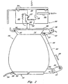
- a beverage brewing device has a server locking mechanism for securing a beverage server 10, such as a coffee pot, in a server receiving portion 40 of the device.
- the beverage server has first and second ends, 16 and 18, respectively.
- the first and second ends have first and second lips, 12 and 14, respectively.
- a first engagement element 20 has a first retaining face 22 which contacts the periphery of the first lip 12, when the beverage server is properly secured.
- the first engagement element is a metal plate having an opening for receiving the first lip.
- the retaining face 22 prevents the beverage server from sliding along the metal plate surface. It will occur to those skilled in the art that alternative plate structures could provide the same function.
- the first engagement element 20 is preferably pivotably mounted within a housing at a pivot point 26 and is biased upwardly such that it applies a force to the first end 16 of the beverage server 10. This force urges the server toward a second engagement element 30.
- the second engagement element 30 is positioned adjacent to the second end 18 of the beverage server 10.
- a second retaining face 32 securely engages a peripheral portion of the second lip 14.
- the second engagement element is preferably pivotally mounted to the housing at a second pivot point 36 and biased downwardly, toward the first engagement element, applying a force to the second end 18 of the beverage server 10. This force urges the server toward the first engagement element 20.
- linkage system for joining the first and second engagement elements 20, 30.
- a pair of identical linkage systems are provided on opposite sides of the beverage brewing device.
- a clear understanding of the function of the linkage system can be gained by a discussion directed to the operation of a single linkage system, as shown in the drawing figures.
- a first linkage 41 is secured to the first engagement element 20 at first pivot point 26.
- a second linkage 43 is secured to the second engagement element 30 at second pivot point 36.
- a third linkage 42 interconnects the first and second linkages at first and second linkage connection points 35 and 37, respectively.
- the third linkage is biased for imparting forces, F 1 and F 2 , on the first and second links, 41 and 43, respectively.
- a spring 29 can be used for this purpose.
- the forces F 1 and F 2 create respective first and second moments, M 1 and M 2 , about first and second pivot points 26 and 36.
- the first and second moments urge the first and second engagement elements toward each other such that the engagement elements cooperate in a clamshell-like manner to secure the beverage server therebetween.
- first and second server lips 12, 14 may be any other suitable mechanism to bias each of the first and second engagement elements toward one another for securely engaging the first and second server lips 12, 14.
- any other suitable mechanism may be used to bias each of the first and second engagement elements toward one another for securely engaging the first and second server lips 12, 14.
- they may be designed to operate in along vertical tracks biased toward one another for engaging the beverage server lips.
- a brew cup locking mechanism is provided for securing a brew cup 52 within a brew cup receiving portion 50 of the beverage brewing device.
- the brew cup locking mechanism includes a brew cup lid 54, a pivotable latch 62 and a pin 60, which cooperate with each other, and with the server locking mechanism, to secure the brew cup in place.
- the brew cup lid 54 has a lid engagement portion 56 extending downwardly therefrom.
- the lid engagement portion has first and second recesses, 57 and 58, respectively, formed on opposing sides of the engagement portion.
- the server and brew cup are simultaneously unlocked by depressing release portion 24 of first engagement element 20.
- Depressing first engagement element 20 biases first linkage 41 toward second linkage 43, via third linkage 42.
- the resulting upward force on the second linkage causes second engagement element 30 to rotate counter-clockwise about second pivot point 36.
- Pivot latch contact portion 34 protruding from the second engagement element contacts a bottom surface of pivotable latch 62 to disengage latching portion 63 from first recess 57.
- brew cup lid 54 is forced upwards until pin 60 engages second recess 58.
- the server and brew cup locking mechanisms are disengaged, allowing beverage server 10 and brew cup 52 to be removed from respective receiving portions 40 and 50.
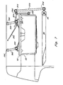
- FIGS. 3 and 4 are partial cutaway views of a beverage brewing device and server which incorporate the invention as described above in FIGS. 1 and 2.
- FIGS. 1 and 2 and FIGS. 3 and 4 common elements are identified with the same reference numerals for simplicity.
- FIGS 3 and 4 illustrate a preferred embodiment of the invention incorporated into a housing.
- the beverage server 10 and brew cup 52 are shown removed from the unit.
- the beverage server 10 and the brew cup 52 are shown locked in position.
- the brew cup locking mechanism comprises a series of linkages which cooperate to releasably secure the brew cup 52 within the brew cup receiving portion.
- the brew cup locking mechanism comprises fourth and fifth linkages, 170 and 180, respectively, interconnecting the brew cup lid 54 and the second engagement element 30.
- Fourth linkage 170 is connected to the second engagement element at first end 172, and to fifth linkage 180 at second end 174.
- Fifth linkage 180 has a first end torsionally-loaded about a third pivot point 182.
- An opposing second end of fifth linkage 180 is pivotably-attached at interconnect point 184 to an upper surface of brew cup lid 54.
- the torsional-loading biases the brew cup lid downwardly against the brew cup 52.
- fourth linkage 170 applies a moment, M 3 , to fifth linkage 180, counteracting the bias created by the torsional loading about third pivot point 182.
- M 3 moment
- a spring-loaded leg 190 attached to the fifth linkage at interconnect point 192, extends vertically to support the brew cup lid in an open position.
- the leg 190 slides along ledge 193 until it engages recess 191.
- the brew cup contacts the leg, releasing it from recess 191 and returning it to an unlocked position.
- a second alternate embodiment of the brew cup locking mechanism comprises a fourth linkage 270 and a second pivotable latch 264 which cooperate independently with features of the brew cup 52 and brew cup lid 54.
- brew cup 52 has an integral S-shaped latching feature 66 and a raised triangular feature 68 formed thereon.
- the second pivotable latch 264 is torsionally-biased to engage a lower segment of S-shaped latching feature 66, preventing the brew cup from being slidably removed from the brew cup receiving portion.
- a first end of the fourth linkage is torsionally-biased about a third pivot point 282.
- a second end of the fourth linkage is pivotably-attached to an upper surface of the brew cup lid at connection point 284.
- fourth linkage 270 forces the brew cup lid 54 downward so that it is received by the brew cup 52.
- a force is applied by second engagement element 30 to second pivotable latch 264, disengaging the latch from the bottom portion of the S-shaped latching feature 66. With the second pivotable latch disengaged, the brew cup is slidably-removed from brew cup receiving portion.
- an upper portion of the S-shaped latching feature 66 engages a lower surface 69 of the triangular portion 68 of the brew cup lid, forcing the brew cup lid away from the brew cup.
- the upper portion of the S-shaped latching feature contacts surface 71, urging the brew cup lid upwards until the second pivotable latch 264 reengages the bottom portion of the S-shaped latching feature.
- the locking mechanism has a second pivotable latch 364 which cooperates with second engagement element 30 via fourth linkage 370.
- First and second support linkages, 380 and 382, respectively, are pivotably attached at respective first ends, 390 and 392, to the device housing, and at respective second ends, 391 and 393, to an upper surface of the brew lid 54.
- Extension spring 395 is connected at opposing ends to the brew cup lid 54 and the beverage brew device housing. Thus, extension spring 395 biases brew cup lid 54 upwardly and away from the top of brew cup 52.
- second pivotable latch 374 biases second pivotable latch 374 to pivot (counter-clockwise) about latch pivot point 366.
- second pivotable latch 364 is unlatched from second end 391 of first support linkage 380.
- extension spring 395 urges support linkages 380 and 382 to rotate about lid support connection points 390 and 392, respectively. This rotational motion urges brew cup lid 54 away from brew cup 52.
- the brew cup is reinserted into the brew cup receiving portion, it contacts brew cup lid engagement portion 396, urging brew lid 54 downward onto the brew cup.
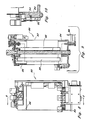
- FIGS. 8-10 illustrate various features of an integral water supply apparatus 80 for use with the beverage brewing system according to the invention.
- the water supply apparatus includes a water tank 82 having first and second ends 84 and 86 respectively, and a water inlet 88.
- One or more electric heating elements 90 are provided and extend into the interior of the tank.
- FIG. 10 is an enlarged view of a circled portion of FIG. 9 showing electronic components 92 which may be MOSFET's.
- the electronic components are preferably used to control the flow of electric power to the heating elements 90.
- the invention is not limited in this regard.
- the electronic components 92 are mounted to the first end cap 84 of the water tank, the end cap preferably being formed of a heat conducting material such as aluminum.
- the electronic components are advantageously mounted near to where cool water enters the tank 82 via water inlet 88. The water thus provided aids in cooling the electronic components 92. Concurrently the electronic components aid in heating the cool water as it flows upwardly in the tank 82.
- the integral is provided to provide cool water into the tank 82.
- a suitable screw fastener 94 or other retaining means may be used to hold the electronic component 92 in place and to further aid in heat transfer.
- FIG. 11 is a block diagram showing the self-test diagnostic system incorporated into the brewing device.
- the beverage brewing system preferably includes one or more sensors 100 which are provided for monitoring various aspects of the brewing system's performance.
- the sensors may be used to monitor water temperature, water flow rate, heating rates, and any other aspect of the brewing system operation.
- the data collected from sensors 100 is provided to microprocessor 102 and can be used for controlling the brew cycle, comparison with pre-determined performance criteria which may be stored in memory 104, and for recording of faults when data results fail to conform to the performance criteria.
- the data, particularly concerning system faults is preferably stored in a non-volatile memory 104.
- the self test diagnostic system for the brewing device includes a data transmitter 108 for downloading of performance and fault data.
- the data transmitter may be configured as an infrared link, an RF link or any other suitable communications link for communicating data stored in the memory 104 to a data recorder 106.
- the data recorder is provided with a corresponding data receiver or transceiver for enabling it to obtain data from the brewing system.
- the system can be configured so that the data recorder 106 initiates the data download from the brewing system by transmitting a report initiation code. However, that would require a bi-directional link.
- the brewing system may be provided with a data download control key sequence (not shown) which will cause the performance data to be downloaded when one or more front panel keys are pressed in sequence by a user.
- a data download control key sequence (not shown) which will cause the performance data to be downloaded when one or more front panel keys are pressed in sequence by a user.
- the brewing system preferably includes a second data link which can also be effected as an optical link, RF link or hard wire link.
- the second data link preferably includes a data transceiver unit 110 which communicates bi-directionally with an onboard aircraft computer 109.
- the brewing system is responsive to commands from the aircraft computer for downloading diagnostic data via data transceiver unit 110.
- the data link can be used for remote operation of the brewing system.
- FIG. 12 shows a beverage server for use in accordance with the present invention.
- the holder is comprised of a liquid container 400, which is positioned securely within a modular handle portion 402.
- the container 400 is comprised of first and second lips 14, 12 respectively as previously described relative to FIGS. 1-4.
- the outer surface of the container 400 is substantially exposed with the beverage server shown for reasons which are discussed below.
- FIG. 13 is an exploded view of the beverage server in FIG. 12 which shows the manner in which the liquid container 400 may be assembled within the modular handle portion 402 and the base member 404.
- the liquid container 400 preferably fits snugly within the inner contours of the handle portion 402.
- the container is held in that position by the base member 404, which is preferably threaded for ease of assembly and removal.
- the base member 404 which is preferably threaded for ease of assembly and removal.
- the modular beverage server shown in FIGS. 12 and 13 is particularly advantageous for use in an aircraft environment where there may be multiple grades of passenger comfort levels offered by an airline.
- the beverage server When the beverage server is used to serve passengers in upgraded levels of flying comfort, such as first class passengers, the liquid container can be manufactured to a higher level of elegance and cost.
- the airline may choose to select a liquid container 400 which has an exterior formed of polished stainless steel or perhaps plated with a precious metal.
- the design of the liquid container portion 400 and the handle portion 402 facilitate interchangeability for use in different grade cabin areas.
- the handle design is not limited to the precise appearance as shown. Rather, the handle portion 402 may be modified or changed in appearance as may be desired, provided that a substantial portion of the overall exterior of the liquid container 400 remains visible when the unit is assembled.
- the beverage holder in FIGS. 12 and 13 has another advantage as well.
- extensive commercial use of the beverage server 10 in an airline environment will inevitably lead to worn and damaged units.
- a handle portion 402 or container portion 400 which becomes worn or damaged can be individually replaced without discarding the entire unit. This will result in an inevitable cost savings to airlines in replacing such equipment.
Landscapes
- Engineering & Computer Science (AREA)
- Food Science & Technology (AREA)
- Physics & Mathematics (AREA)
- Thermal Sciences (AREA)
- Apparatus For Making Beverages (AREA)
- Devices For Dispensing Beverages (AREA)
- Table Devices Or Equipment (AREA)
Description
Claims (20)
- A beverage brewing device having a beverage server locking mechanism for securing a beverage server (10) within a server receiving portion (40) of said beverage brewing device, the beverage server locking mechanism comprising:a first engagement element (20), said first engagement element (20) configured for engaging a first lip (12) formed on a first end (16) of said beverage server, and biased for applying a force thereto, the force urging said beverage server (10) toward a second support structure of said beverage brewing device situated adjacent to an opposing second end (18) of said beverage server (10), whereby said beverage server is secured within said server receiving portion (40) when the beverage brewing apparatus is subjected to accelerative and vibrational forces.
- A beverage brewing device as recited in claim 1, wherein said second support structure comprises a second engagement (30) element biased for engaging a second lip (14) formed on said opposing second end (18) of said beverage server (10).
- A beverage brewing device as recited in claim 2, wherein said second engagement element (30) has a second retaining face (32) for engaging a peripheral portion of said second lip (14).
- A beverage brewing device as recited in claim 3, wherein said brew cup (52) is unlocked by applying a downward force upon a release portion (24) of said first engagement element (20).
- A beverage brewing device as recited in claim 4, wherein said server (10) and brew cup locking mechanisms are configured to cooperate such that said server locking mechanism must be in an unlocked position prior to unlocking said brew cup locking mechanism.
- A beverage brewing device as recited in claim 2, wherein said first and second engagement elements (20, 30) are joined by a linkage system (41, 42, 43).
- A beverage brewing device as recited in claim 6, wherein the bias for said first and second engagement elements (20, 30) is provided via said linkage system (41,42,43).
- A beverage brewing device as recited in claim 7, wherein said linkage system comprises:a first linkage (41) secured to said first engagement element (20) at a first pivot point (26);a second linkage (43) secured to said second engagement element (30) at a second pivot point (36); anda third linkage (42) interconnecting said first and second linkages (41, 43), whereby
said third linkage (42) imparts first and second opposing rotational moments to said first and second links (41, 43), respectively, the first moment urging said first engagement element (20) upward and the second moment urging said second engagement element (30) downward. - A beverage brewing device as recited in claim 8, further comprising a brew cup locking means configured for securing a brew cup (52) within a brew cup receiving portion (50) of said beverage brewing device.
- A beverage brewing device as recited in claim 9, said brew cup locking means comprises:a downwardly-biased brew cup lid (54) having an integral tab (56), said tab extending downwardly from said brew cup lid and having first and second recesses (57, 58) formed therein;a pivotable latch (62) having a latching end (63), said latching end for engaging the first recess (57) formed in said integral tab (56); anda pin (60) for engaging the second recess (58) formed in said integral tab.
- A beverage brewing device as recited in claim 10, wherein said brew cup locking means (54, 62, 60) is configured to be unlocked by applying a downward force upon a release portion (24) of said first engagement element (20).
- A beverage brewing device as recited in claim 9, said brew cup locking means comprising:a fourth linkage (170);a fifth linkage (180) having first and second ends (172, 174); anda pivoting, spring-loaded leg (190) extending from said fifth linkage,
said fourth linkage (170) interconnecting said second
engagement element (30) and said fifth linkage (180),
said fifth linkage (180) torsionally-loaded about a third pivot point (182) adjacent to said first end and mechanically attached to said brew cup lid (54)at said second end, said torsional loading biasing said brew cup lid downward against said brew cup. - A beverage brewing device as recited in claim 12, whereby said brew cup locking means is configured to be unlocked by applying a downward force upon a release portion (24) of said first engagement element (20).
- A beverage brewing device as recited in claim 9, said brew cup locking means comprising:a fourth linkage (270) having first and second ends; anda pivotable latch (264),
said fourth linkage torsionally-loaded about a third pivot point (282) adjacent to said first end, and mechanically attached to said brew cup lid at said second end (284), said fourth linkage torsionally-loaded for biasing said brew cup lid (54) downward against said brew cup (52), and
said pivotable latch (264) torsionally-loaded for engaging an integral latch receiving portion (66) on a side of said brew cup. - A beverage brewing device as recited in claim 14, whereby said brew cup locking means is configured to be unlocked by applying a downward force upon a release portion (24) of said first engagement element (20).
- A beverage brewing device as recited in claim 9, said brew cup locking means comprising:a fourth linkage (370) having first and second ends;a pivotable latch (364); andan extension spring (395) having a first end attached to said brew cup lid (54) and a second end attached to the device housing,
the first end of said fourth linkage (370) attached to said second engagement element (30), the second end of said fourth linkage attached to said pivotable latch (364),
said pivotable latch (364) torsionally loaded about a third pivot point (366)such that said pivotable latch forces said brew cup lid (54) downward against said brew cup (52), and
said extension spring (395) biasing said brew cup lid (54) upward away from said brew cup (52), forcing said brew cup lid away from said brew cup when said pivotable (364) latch disengages said brew cup lid. - A beverage brewing device as recited in claim 1, wherein said first engagement element (20) has a first retaining face (22) for engaging a peripheral portion of said first lip (12).
- A beverage brewing device as recited in claim 17, wherein said first retaining face (22) is a peripheral wall of an opening extending through said first engagement element (20).
- A beverage brewing device as recited in claim 17, wherein said first retaining face (22) is a peripheral wall of a recess formed in said first engagement element (20).
- A beverage brewing device as recited in claim 17, wherein said first retaining face (22) extends upwardly away from said first engagement element (20).
Applications Claiming Priority (3)
| Application Number | Priority Date | Filing Date | Title |
|---|---|---|---|
| US25285 | 1998-02-16 | ||
| US09/025,285 US6047630A (en) | 1998-02-16 | 1998-02-16 | Beverage brewing device having an integral beverage server locking apparatus |
| PCT/US1999/003184 WO1999040828A1 (en) | 1998-02-16 | 1999-02-16 | Beverage brewing device having an integral beverage server locking apparatus |
Publications (3)
| Publication Number | Publication Date |
|---|---|
| EP1056378A1 EP1056378A1 (en) | 2000-12-06 |
| EP1056378A4 EP1056378A4 (en) | 2002-12-04 |
| EP1056378B1 true EP1056378B1 (en) | 2004-01-28 |
Family
ID=21825132
Family Applications (1)
| Application Number | Title | Priority Date | Filing Date |
|---|---|---|---|
| EP99908161A Expired - Lifetime EP1056378B1 (en) | 1998-02-16 | 1999-02-16 | Beverage brewing device having an integral beverage server locking apparatus |
Country Status (6)
| Country | Link |
|---|---|
| US (2) | US6047630A (en) |
| EP (1) | EP1056378B1 (en) |
| JP (4) | JP3533663B2 (en) |
| AU (1) | AU2765899A (en) |
| DE (1) | DE69914459T2 (en) |
| WO (1) | WO1999040828A1 (en) |
Families Citing this family (30)
| Publication number | Priority date | Publication date | Assignee | Title |
|---|---|---|---|---|
| US6227101B1 (en) * | 1999-12-10 | 2001-05-08 | Masoud Rabadi | Coffeemaker with automated interlocks |
| ITRM20010098U1 (en) * | 2001-05-16 | 2002-11-16 | Iacobucci S P A | COFFEE DISPENSING MACHINE. |
| WO2003030696A1 (en) * | 2001-10-05 | 2003-04-17 | Hp Intellectual Corp. | Coffee maker |
| AU2003260870A1 (en) | 2002-09-27 | 2004-04-19 | Koninklijke Philips Electronics N.V. | Apparatus for preparing coffee |
| US7165488B2 (en) | 2003-12-12 | 2007-01-23 | Keurig, Incorporated | Brew chamber for a single serve beverage brewer |
| US6904840B1 (en) | 2004-01-28 | 2005-06-14 | Grindmaster Corporation | Brewer apparatus with improved tray assembly |
| JP4188854B2 (en) * | 2004-02-20 | 2008-12-03 | 株式会社ジャムコ | Folding coffee maker |
| US7891287B2 (en) * | 2004-06-16 | 2011-02-22 | Mag Aerospace Industries, Inc. | Coffee maker suitable for aircraft use |
| EP1676509A1 (en) * | 2004-12-30 | 2006-07-05 | Rhea Vendors S.p.A. | Process and apparatus for controlling the preparation of brewed beverages |
| US20060254428A1 (en) * | 2005-05-14 | 2006-11-16 | Glucksman Dov Z | Coffee making apparatus |
| CN2920114Y (en) * | 2005-08-15 | 2007-07-11 | 王冬雷 | Coffee-making machine brewing locking device |
| US7513192B2 (en) * | 2006-03-23 | 2009-04-07 | Keurig, Incorporated | Beverage forming device with opening/closing mechanism for a beverage cartridge receiver |
| US7861644B2 (en) * | 2006-03-31 | 2011-01-04 | C&D Zodiac, Inc. | Beverage maker |
| ES2359577T3 (en) * | 2006-06-09 | 2011-05-24 | Nestec S.A. | MODULAR DEVICE FOR THE PRODUCTION OF DRINKS WITH RECEPTION STATION. |
| US20080017042A1 (en) * | 2006-07-19 | 2008-01-24 | Robert Almblad | Automated coffee brewing and dispensing apparatus |
| US8107803B1 (en) | 2007-04-16 | 2012-01-31 | Richard W. Heim | Non-scaling flow through water heater |
| US20090071342A1 (en) * | 2007-09-14 | 2009-03-19 | Jamal Hammad | Thermal carafe enclosure to capture steam and increase coffee temperature |
| CA2640783A1 (en) * | 2007-10-08 | 2009-04-08 | William L. Spencer | Coffee maker brewbasket with carafe locking mechanism |
| CA2751503A1 (en) | 2009-02-04 | 2010-08-12 | Bunn-O-Matic Corporation | Brewer |
| US8074514B1 (en) | 2009-05-24 | 2011-12-13 | Richard W. Heim | Liquid level sensor with conductive torsion springs |
| PL2523587T3 (en) * | 2010-01-15 | 2014-03-31 | Nestec Sa | Ergonomic service unit for beverage preparation machines |
| US8927037B2 (en) | 2011-02-08 | 2015-01-06 | Kevin B. Kihnke | Disposable cartridge for brewed beverages |
| US20130174743A1 (en) * | 2012-01-06 | 2013-07-11 | B/E Aerospace, Inc. | Aircraft brewing apparatus |
| DE202012103158U1 (en) * | 2012-08-21 | 2013-11-25 | Melitta Europa Gmbh & Co. Kg | coffee machine |
| USD729003S1 (en) | 2014-01-17 | 2015-05-12 | Keurig Green Mountain, Inc. | Beverage carafe |
| US9173519B2 (en) | 2014-01-17 | 2015-11-03 | Keurig Green Mountain, Inc. | Method and apparatus for beverage carafe detection |
| US9844296B2 (en) * | 2014-03-11 | 2017-12-19 | Helen Of Troy Limited | Beverage brewing device |
| US10555637B2 (en) | 2016-03-04 | 2020-02-11 | Bunn-O-Matic Corporation | Brewer with temperature responsive control valve |
| US10932609B2 (en) * | 2018-05-03 | 2021-03-02 | Rockwell Collins, Inc. | Aircraft galley brewing apparatus |
| GB202006177D0 (en) * | 2020-04-27 | 2020-06-10 | Ipeco Holdings Ltd | Beverage dispensing machine |
Family Cites Families (8)
| Publication number | Priority date | Publication date | Assignee | Title |
|---|---|---|---|---|
| US2637266A (en) * | 1949-05-07 | 1953-05-05 | Grado Calogero | Steam coffee maker |
| US3181732A (en) * | 1961-01-26 | 1965-05-04 | Gen Foods Corp | Beverage apparatus |
| US4949627A (en) * | 1989-03-09 | 1990-08-21 | Nordskog Robert A | Coffee maker for use in aircraft |
| US5183998A (en) * | 1990-05-30 | 1993-02-02 | Mr. Coffee Inc. | Apparatus and method for heating water for infusion and the like |
| JPH0659347B2 (en) | 1990-10-23 | 1994-08-10 | 株式会社プリンス | Detachment device for supporting frame such as futon in sewing machine |
| DE4426233A1 (en) * | 1994-07-23 | 1996-01-25 | Braun Ag | Beverage jug with retaining ring |
| US5704275A (en) * | 1996-12-31 | 1998-01-06 | Bloomfield Industries Canada, Limited | Electronic brew control system |
| PL182757B1 (en) * | 1997-02-16 | 2002-02-28 | Zelmer Sa | Percolator-type coffee-making machine suitable for making also other beverages by infusive exhtraction with hot or boiling water |
-
1998
- 1998-02-16 US US09/025,285 patent/US6047630A/en not_active Expired - Fee Related
- 1998-11-13 US US09/191,829 patent/US6050175A/en not_active Expired - Fee Related
-
1999
- 1999-02-16 EP EP99908161A patent/EP1056378B1/en not_active Expired - Lifetime
- 1999-02-16 WO PCT/US1999/003184 patent/WO1999040828A1/en not_active Ceased
- 1999-02-16 AU AU27658/99A patent/AU2765899A/en not_active Abandoned
- 1999-02-16 JP JP2000531093A patent/JP3533663B2/en not_active Expired - Lifetime
- 1999-02-16 DE DE69914459T patent/DE69914459T2/en not_active Expired - Lifetime
-
2004
- 2004-01-08 JP JP2004003113A patent/JP3943084B2/en not_active Expired - Lifetime
- 2004-01-08 JP JP2004003114A patent/JP2004188212A/en active Pending
- 2004-01-08 JP JP2004003513A patent/JP2004181252A/en active Pending
Also Published As
| Publication number | Publication date |
|---|---|
| JP3943084B2 (en) | 2007-07-11 |
| JP3533663B2 (en) | 2004-05-31 |
| WO1999040828A1 (en) | 1999-08-19 |
| DE69914459D1 (en) | 2004-03-04 |
| US6050175A (en) | 2000-04-18 |
| US6047630A (en) | 2000-04-11 |
| JP2002502650A (en) | 2002-01-29 |
| JP2004188212A (en) | 2004-07-08 |
| JP2004181252A (en) | 2004-07-02 |
| EP1056378A1 (en) | 2000-12-06 |
| JP2004141670A (en) | 2004-05-20 |
| EP1056378A4 (en) | 2002-12-04 |
| AU2765899A (en) | 1999-08-30 |
| DE69914459T2 (en) | 2004-10-28 |
Similar Documents
| Publication | Publication Date | Title |
|---|---|---|
| US6047630A (en) | Beverage brewing device having an integral beverage server locking apparatus | |
| US7644650B2 (en) | Water heater and coffee maker for aircraft | |
| EP1768529B1 (en) | Coffee maker suitable for aircraft use | |
| CN110432770B (en) | Aircraft galley brewing apparatus | |
| US20060037483A1 (en) | Coffee brewer with loading and ejection mechanism for a coffee cartridge | |
| JP2014526325A (en) | Clean multi-system beverage machine | |
| US20140227413A1 (en) | Hot Beverage Brewing System and Use Thereof | |
| US9314129B2 (en) | Head assembly for brewing apparatus | |
| US7565860B1 (en) | Multi-functional hot beverage brewing device | |
| EP3282903B1 (en) | Beverage dispensing machine | |
| CA2930643A1 (en) | Beverage preparation apparatus | |
| CA2703873C (en) | Method, system and apparatus for housing and dispensing liquid | |
| US20250120534A1 (en) | Beverage maker with latching mechanism | |
| CA2077403C (en) | Beverage making apparatus having improved serviceability | |
| NL1026319C1 (en) | Multifunctional coffee maker. | |
| CN103169365B (en) | There is the cooking equipment that has safety device of heating plate | |
| EP1056379B1 (en) | Beverage brewing device having an integral beverage server locking apparatus | |
| JPS59174119A (en) | Extraction apparatus of coffee or the like | |
| JPH05115374A (en) | Electric kettle | |
| JPH0532023Y2 (en) | ||
| JPS6179426A (en) | Coffee extractor | |
| JP2000041853A (en) | Electric water heater | |
| JPH0234608B2 (en) | ||
| JPH0234609B2 (en) | ||
| JPS60222014A (en) | beverage extractor |
Legal Events
| Date | Code | Title | Description |
|---|---|---|---|
| PUAI | Public reference made under article 153(3) epc to a published international application that has entered the european phase |
Free format text: ORIGINAL CODE: 0009012 |
|
| 17P | Request for examination filed |
Effective date: 20000816 |
|
| AK | Designated contracting states |
Kind code of ref document: A1 Designated state(s): DE FR GB IT |
|
| A4 | Supplementary search report drawn up and despatched |
Effective date: 20021017 |
|
| AK | Designated contracting states |
Kind code of ref document: A4 Designated state(s): DE FR GB IT |
|
| 17Q | First examination report despatched |
Effective date: 20030124 |
|
| GRAP | Despatch of communication of intention to grant a patent |
Free format text: ORIGINAL CODE: EPIDOSNIGR1 |
|
| GRAS | Grant fee paid |
Free format text: ORIGINAL CODE: EPIDOSNIGR3 |
|
| GRAA | (expected) grant |
Free format text: ORIGINAL CODE: 0009210 |
|
| AK | Designated contracting states |
Kind code of ref document: B1 Designated state(s): DE FR GB IT |
|
| REG | Reference to a national code |
Ref country code: GB Ref legal event code: FG4D |
|
| REF | Corresponds to: |
Ref document number: 69914459 Country of ref document: DE Date of ref document: 20040304 Kind code of ref document: P |
|
| ET | Fr: translation filed | ||
| PLBE | No opposition filed within time limit |
Free format text: ORIGINAL CODE: 0009261 |
|
| STAA | Information on the status of an ep patent application or granted ep patent |
Free format text: STATUS: NO OPPOSITION FILED WITHIN TIME LIMIT |
|
| 26N | No opposition filed |
Effective date: 20041029 |
|
| REG | Reference to a national code |
Ref country code: FR Ref legal event code: PLFP Year of fee payment: 18 |
|
| REG | Reference to a national code |
Ref country code: FR Ref legal event code: PLFP Year of fee payment: 19 |
|
| REG | Reference to a national code |
Ref country code: FR Ref legal event code: PLFP Year of fee payment: 20 |
|
| PGFP | Annual fee paid to national office [announced via postgrant information from national office to epo] |
Ref country code: GB Payment date: 20180227 Year of fee payment: 20 Ref country code: DE Payment date: 20180227 Year of fee payment: 20 |
|
| PGFP | Annual fee paid to national office [announced via postgrant information from national office to epo] |
Ref country code: IT Payment date: 20180222 Year of fee payment: 20 Ref country code: FR Payment date: 20180227 Year of fee payment: 20 |
|
| REG | Reference to a national code |
Ref country code: DE Ref legal event code: R071 Ref document number: 69914459 Country of ref document: DE |
|
| REG | Reference to a national code |
Ref country code: GB Ref legal event code: PE20 Expiry date: 20190215 |
|
| PG25 | Lapsed in a contracting state [announced via postgrant information from national office to epo] |
Ref country code: GB Free format text: LAPSE BECAUSE OF EXPIRATION OF PROTECTION Effective date: 20190215 |