EP1056114A2 - Ion implantation apparatus - Google Patents
Ion implantation apparatus Download PDFInfo
- Publication number
- EP1056114A2 EP1056114A2 EP00303233A EP00303233A EP1056114A2 EP 1056114 A2 EP1056114 A2 EP 1056114A2 EP 00303233 A EP00303233 A EP 00303233A EP 00303233 A EP00303233 A EP 00303233A EP 1056114 A2 EP1056114 A2 EP 1056114A2
- Authority
- EP
- European Patent Office
- Prior art keywords
- wheel
- ion beam
- axis
- wafer support
- motor
- Prior art date
- Legal status (The legal status is an assumption and is not a legal conclusion. Google has not performed a legal analysis and makes no representation as to the accuracy of the status listed.)
- Withdrawn
Links
- 238000005468 ion implantation Methods 0.000 title claims abstract description 16
- 238000010884 ion-beam technique Methods 0.000 claims abstract description 55
- 239000007943 implant Substances 0.000 claims abstract description 33
- 238000000034 method Methods 0.000 claims description 20
- 230000001133 acceleration Effects 0.000 claims description 11
- 239000000758 substrate Substances 0.000 claims description 9
- 238000002513 implantation Methods 0.000 claims description 8
- 235000012431 wafers Nutrition 0.000 description 30
- 230000008569 process Effects 0.000 description 5
- 150000002500 ions Chemical class 0.000 description 4
- 239000004065 semiconductor Substances 0.000 description 3
- 238000013461 design Methods 0.000 description 2
- 238000010586 diagram Methods 0.000 description 2
- 238000001914 filtration Methods 0.000 description 2
- 230000006870 function Effects 0.000 description 2
- 230000006872 improvement Effects 0.000 description 2
- 238000004519 manufacturing process Methods 0.000 description 2
- 230000007246 mechanism Effects 0.000 description 2
- 238000012986 modification Methods 0.000 description 2
- 230000004048 modification Effects 0.000 description 2
- 230000003287 optical effect Effects 0.000 description 2
- 230000009286 beneficial effect Effects 0.000 description 1
- 239000013626 chemical specie Substances 0.000 description 1
- 238000004891 communication Methods 0.000 description 1
- 238000010276 construction Methods 0.000 description 1
- 230000001419 dependent effect Effects 0.000 description 1
- 238000006073 displacement reaction Methods 0.000 description 1
- 230000002349 favourable effect Effects 0.000 description 1
- 238000005259 measurement Methods 0.000 description 1
- 238000012795 verification Methods 0.000 description 1
Images



Classifications
-
- H—ELECTRICITY
- H01—ELECTRIC ELEMENTS
- H01J—ELECTRIC DISCHARGE TUBES OR DISCHARGE LAMPS
- H01J37/00—Discharge tubes with provision for introducing objects or material to be exposed to the discharge, e.g. for the purpose of examination or processing thereof
- H01J37/30—Electron-beam or ion-beam tubes for localised treatment of objects
- H01J37/317—Electron-beam or ion-beam tubes for localised treatment of objects for changing properties of the objects or for applying thin layers thereon, e.g. for ion implantation
- H01J37/3171—Electron-beam or ion-beam tubes for localised treatment of objects for changing properties of the objects or for applying thin layers thereon, e.g. for ion implantation for ion implantation
-
- H—ELECTRICITY
- H01—ELECTRIC ELEMENTS
- H01J—ELECTRIC DISCHARGE TUBES OR DISCHARGE LAMPS
- H01J2237/00—Discharge tubes exposing object to beam, e.g. for analysis treatment, etching, imaging
- H01J2237/20—Positioning, supporting, modifying or maintaining the physical state of objects being observed or treated
- H01J2237/202—Movement
- H01J2237/20221—Translation
- H01J2237/20228—Mechanical X-Y scanning
-
- H—ELECTRICITY
- H01—ELECTRIC ELEMENTS
- H01J—ELECTRIC DISCHARGE TUBES OR DISCHARGE LAMPS
- H01J2237/00—Discharge tubes exposing object to beam, e.g. for analysis treatment, etching, imaging
- H01J2237/245—Detection characterised by the variable being measured
- H01J2237/24507—Intensity, dose or other characteristics of particle beams or electromagnetic radiation
- H01J2237/24514—Beam diagnostics including control of the parameter or property diagnosed
- H01J2237/24528—Direction of beam or parts thereof in view of the optical axis, e.g. beam angle, angular distribution, beam divergence, beam convergence or beam landing angle on sample or workpiece
Definitions
- the invention relates to ion implantation apparatus. Such an apparatus is used for implanting ions of preselected chemical species into semiconductor wafers for manufacturing desired semiconductor electronic devices.
- the present invention is particularly concerned with apparatus for scanning semiconductor wafers under treatment relative to the ion beam to ensure an even dose of ions is delivered to all parts of the wafer.
- wafers for treatment are mounted at a number of discreet positions around the periphery of an implant wheel.
- the wheel is mounted at the free end of a scanning arm which is mounted at its other end for reciprocating motion about a scanning axis.
- the scanning arm and implant wheel are located in a vacuum chamber to which a beam of desired ions is directed from an ion source.
- the various wafers mounted around the periphery of the wheel are brought successively in front of the beam.
- the scanning arm more slowly moves the axis of rotation of the wheel to and fro, so that the ion beam is progressively scanned over the whole surface of the wafers.
- the scanning arm of the apparatus is mounted for reciprocating movement by means of a rotary vacuum seal on the scan axis of the scanning arm.
- the implant wheel is driven by means of drive shafts and belts from outside thee vacuum chamber, with the drive belts extending the length of the scanning arm to drive the shaft of the implant wheel rotatably mounted at the free end of the scanning arm.
- the scan arm is driven by a leadscrew, arranged such that the velocity of the leadscrew is proportional to the velocity of the centre of the wheel relative to the beam.
- Custom electronics then provide a control velocity to the leadscrew that varies as a function of wheel radius in the beam.
- This arrangement provides very high levels of process uniformity.
- the whole scanning system is mounted at an angle relative to the ion beam of typically 7°, such that the ion beam is perpendicular to a wafer mounted on the wheel which is canted inwardly towards 7° the axis of the wheel. This mounting causes motion of the wafer along the line of the ion beam as the wheel is scanned. Because the beam is not a perfectly parallel beam, this movement causes non-uniformities in the implantation operation.
- an ion implantation apparatus comprising a vacuum chamber, an ion beam generator to generate an ion beam in the vacuum chamber, an implant wheel in the vacuum chamber, having a plurality of circumferentially distributed wafer support elements each having a wafer support surface canted inwardly towards the centre of the implant wheel, a scanning arm mounted for reciprocal movement about a scan axis and having a free end supporting the implant wheel for rotation about a wheel axis, so that rotation of the implant wheel about the wheel axis brings the wafer support elements successively to intercept the ion beam and reciprocation of the scanning arm about the scan axis scans the ion beam across the wafer support elements, wherein the wheel is rotatable with respect to the arm about a tilt axis, which substantially intersects the wheel axis and ion beam, to vary the direction of implantation, and wherein the scan axis is substantially parallel to the direction of the ion beam, and the direction of the wheel axis
- This arrangement ensures that the wafers are always kept at a constant distance with respect to the ion beam, thereby achieving uniform implantation. Even when the wheel is tilted to vary the implantation angle, the position of the tilt axis ensures that there is little, if any, variation in the distance of the wafers with respect to the ion beam.
- the tilt axis is preferably substantially perpendicular to the wheel axis as this provides a simple construction with little movement of the substrate relative to the ion beam when the wheel is tilted. However, if even this little movement is not tolerable, the tilt axis can substantially pass through the plane of the substrate support for the substrate being scanned by the ion beam thereby eliminating any relative movement between the substrate and the ion beam. Any positions between these two particular examples will also give favourable results.
- ion implantation apparatus comprising a vacuum chamber, an ion beam generator to generate an ion beam in the vacuum chamber, an implant wheel in the vacuum chamber, having a plurality of circumferentially distributed wafer support elements, a scanning arm mounted for reciprocal movement about a scan axis and having a free end supporting the implant wheel for rotation about a wheel axis, so that rotation of the implant wheel about the wheel axis brings the wafer support elements successively to intercept the ion beam and reciprocation of the scanning arm about the scan axis scans the ion beam, across the wafer support elements, and a motor for driving the scanning arm, the motor having a drive shaft connected through a gearbox which has an output shaft driving the scanning arm, wherein a first rotary position detector is provided on the drive shaft and a second rotary position detector is provided on the output shaft.
- This arrangement provides an accurate way of determining the scanning position of the wafers.
- the use of the rotary position detectors either side of the gearbox allows a very accurate measurement to be made as the drive shaft is rotating faster than the output shaft by an amount equal to the ratio of the gears, which can be typically 170:1.
- the data produced by the rotary position detectors can be used to provide full positional information relating to the scan arm, and this can therefore be used for safety circuits and other related equipment thereby eliminating the need for the optical sensors provided in the prior art.
- the use of the two rotary position detectors allows the mechanical integrity of the apparatus to be readily verified using a method comprising the steps of taking a reading from the second rotary position detector, calculating the theoretical position of the motor from the reading taken from the second rotary position detector and from the gearbox ratio, measuring the actual position of the motor from the first rotary position detector, and comparing the actual position of the motor with the theoretical position of the motor.
- the velocity profile of the apparatus can easily be corrected to allow for rotary position detector non-linearity.
- a method comprising the steps of driving the scan arm across a range of movement, and noting readings from both rotary position detectors in each position, calculating from each first rotary position detector reading and from the gearbox ratio the theoretical second rotary position detector reading in each position, subtracting the theoretical second rotary position detector reading from the actual second rotary position detector reading in each position, filtering the data generated in order to remove errors generated by sources other than second rotary position detector non-linearity to obtain data indicative only of second rotary position detector non-linearity, differentiating this data to produce data indicative of velocity error, and applying this velocity error to a look up table of the desired velocity profile.
- a method of driving a member through a pre-determined velocity profile comprising compiling numerical tables for velocity and position for the velocity profile, using values from the numerical tables instructing the member to move from a first position at which it is travelling at a first velocity to a second position at which it is travelling at a second velocity at an acceleration at which the member will reach the second velocity before it reaches the second position and will hence stop accelerating until it reaches the second position, and selecting the rate of reading values from the numerical tables to be fast enough that the inherent lag in the control system causes smooth acceleration of the arm throughout the velocity profile.
- the member to be driven may be the scan arm referred to above.
- an ion implantation apparatus comprising a vacuum chamber, an ion beam generator to generate an ion beam in the vacuum chamber, an implant wheel in the vacuum chamber, having a plurality of circumferentially distributed wafer support elements, a scanning arm mounted for reciprocal movement about a scan axis and having a free end supporting the implant wheel for rotation about a wheel axis, so that rotation of the implant wheel about said wheel axis brings the wafer support elements successively to intercept the ion beam and reciprocation of the scanning arm about the scan axis scans the ion beam across the wafer support elements, and a motor for driving the scanning arm, the motor having a drive shaft connected directly to a cycloid type gearbox, the output of which directly drives the scanning arm.
- the scan arm requires only a relatively low power motor and low torque gearbox to drive the scan arm.
- the use of a cycloid type gearbox, which is capable of generating very large torque may seem a surprising choice.
- such an arrangement is beneficial as it is capable of resisting very high reserve torque in case of failure.
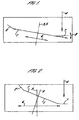
- Fig 1. shows the orientation of the various axes of the implant apparatus of (U.S. 5,641,969.
- the scan wheel 1 is provided with a plurality of circumferentially spaced wafer support elements 2 canted inwardly towards the wheel axis 3 about which the implant wheel 1 is arranged to spin.
- the wheel axis 3 is at an angle with respect to the direction of the ion beam 4 as indicated by the arrow in Fig 1.
- the scan arm is rotatable about a scan axis 5 which is directly below the wheel axis 3 and extends in the same direction of the wheel axis 3.
- the wheel 1 spins about the wheel axis 3 as the scan arm reciprocably scans the wheel 1 in a direction of arrow 6.
- the wafer support surfaces 7 on which wafer are supported are kept perpendicular to the direction of the ion beam 4.
- the wafer support surfaces 7 will be moved in the direction of the ion beam 4 as indicated by arrow 8.
- the wheel 1 is also rotatable through a limited angle about a first tilt axis 9A perpendicular to the wheel axis, extending across a diameter of the wheel 1 and intersecting the ion beam 4.
- the wheel 1 may be rotatable through a limited angle about a second tilt axis 9B passing through the plane of the substrate on the wafer support surface 7 being scanned.
- Fig 2 the same reference numerals are used to designate the same parts as in Fig 1.
- the fundamental difference between Figs 1 and 2 is that, in Fig 2, the scan axis 5 is now parallel to the direction of the ion beam 4 while the wheel axis 3 is angularly offset with respect to the scan axis 5.
- the angular offset is such that the perpendicular relationship between the support surfaces 7 and ion beam 4 is preserved.
- the scan arm moves the wheel in the direction of the arrow 6, the wafer support surfaces 7 will remain in the same plane. In other words, they will not move in the direction of the ion beam 4.
- the wheel is rotated about the first tilt axis 9A to vary the angle of implantation, it is apparent from Fig. 2 that there will be very little travel of the support surfaces 7 in the ion beam direction.
- the wheel is rotated about the second tilt axis 9B even this little travel is eliminated
- Fig 3 shows the drive train for the scan arm 10.
- the scan arm 10 is driven by a motor 11 having a drive shaft 12 which inputs directly into a cycloid type gearbox 13 having an output shaft 14 which directly drives the scan arm 10.
- the motor 11 is a relatively low power brushless dc servo motor, while the gearbox is a cycloid type gearbox such as that produced by Sumitoyo Corporation of Japan.
- the gear box 13 is chosen as one which will provide high torque, which although is not required for the operation of the scan arm is used for its ability to resist high torque in the event of failure.
- the resolvers are essentially rotary position detectors which produce an output proportional to the rotational displacement of the respective shaft 12, 14. It will be appreciated that the readings from the two resolvers will be substantially proportional to one another, the constant of proportionality being the ratio provided by the gearbox 13.
- the housing of the gearbox 13 is mounted to the housing process chamber of the implant apparatus via outer housing 17 using a plurality of bolts 18.
- the output shaft 14 is fitted to the gearbox by a plurality of bolts 18' and extends through a differential pump seal assembly 19 of conventional design.
- a cable guide 14' is provided within the output shaft to guide cables into the interior of output shaft 14. All of the scan load, and mass is carried to the gearbox 13.
- the gearbox outer housing 17 extends inside the process chamber and carries the outer portion of the seal assembly.
- the resolvers are fitted to the apparatus in a random configuration so initially their positions are meaningless.
- the scan arm is moved to a reference position (e.g. a vertical position), and a button pressed to teach the reference position to the controller software.
- the values from the two resolvers are stored in non-volatile memory.
- the theoretical value of the motor resolver can be calculated for any position of the output resolver. This is used at start-up to verify the position of the scan arm, and is periodically used to verify the correct operation of the two resolvers, their circuits, and the integrity of the mechanical system as described in more detail below.
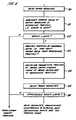
- step 30 a reading is taken from the output resolver upon start-up, and this reading is subtracted from the reference position at step 31 in order to determine the position of the arm.
- Step 32 clarifies whether or not this reading is within the correct limits and notifies the operator if there is a problem. Knowing the gear box ratio, it is possible to determine at step 33 the number of motor revs from the motor position and calculate at step 34 the theoretical position of the motor using the stored reference value for the motor resolver at the reference position.
- step 35 a reading is taken from the motor resolver, and step 36 determines whether or not the difference between the calculated and read values of the motor resolver is within acceptable limits. If not, the system alerts an operator. If the difference is within acceptable limits, this provides an indication of the integrity of a mechanical and electronic systems.
- the position loop is closed round the output resolver.
- the motor controller receives feedback from the output resolver, and drives the motor until the output resolver reaches the desired position.
- the output from the motor resolver is not used to control the arm, but is only used for motor communication.
- any position error from the output resolver will result in the equivalent error appearing on the scan profile. Resolver errors are reduced to a minimum by the use of precision mechanical and electronic parts, but a significant error can still exist. To compensate for this, the system performs the calibration operation as shown in Fig.5.
- the apparatus is then switched to feedback mode in which only the motor resolver is used for motion as shown in step 43.
- step 44 the arm is moved to one end of its travel, and is moved in small steps across its entire range of movement, as determined by the motor resolver, and the value for the output resolver is stored in each case.
- the arm is returned at step 45 to its reference position.
- the theoretical value of the output resolver is calculated at step 46 from the reading of the motor resolver and the gearbox ratio. This is subtracted from the read values from the output resolvers at step 47 to generate the set of error values which are as shown graphically in Fig.6A.
- the errors come from two sources, namely gearbox ripple, and the output resolver non-linearity.
- the gearbox ripple has a frequency determined by the gearbox manufacture, and can be readily removed by filtration at step 48 to provide an error plot as shown in Fig. 6B which represents only the error generated by the output resolver non-linearity.
- the velocity error as shown in Fig.6C can be generated.
- This velocity error data can then be applied to a look up table containing the figures for the required theoretical velocity profile as shown at step 50. For reasons that will be described in more detail below, this velocity profile data is then interpolated to provide a table which typically has 400 sets of data as shown at step 51.
- the feedback mode is then changed at step 52 so that the position is controlled by the output resolver for normal operation.
- a control system is required in order to ensure that the scan arm is accurately moved through the velocity profile generated as described above.
- the established method for this is to use three data tables, holding (say) 50 values each of position, velocity and acceleration, based on equal intervals of position. These values represent a series of linear segments approximating the velocity profile. One such segment is shown in Fig. 7A.
- the motor is then instructed to accelerate at a given rate, from a first velocity V1 to a second velocity V2, as illustrated in Fig. 7A until a given position is reached, these values coming from the data tables. When the given position is reached, a new instruction is issued with the next values from the tables. Whilst being adequate for most applications, this method has failings in this application.
- the overall error is largely dependant upon the tuning of the closed loop control system, as this controls how quickly the motor assumes the commanded acceleration value, causing the accuracy to vary from system to system.
- a position error develops which accumulates with time. In other words, because the arm is not accelerated instantaneously to the required acceleration, it may not achieve the desired velocity at the desired position.
- the improved method developed involves creating only two much larger data tables typically having 400 values each for velocity and position which are calculated to give equal distance increments as described above. This means that the motor is fed new velocity values more frequently as its speed increases. This is shown in Fig 7B.
- the values for V 1 and V 2 are the same as for Fig 7A above.
- the arm is given ten intermediate velocity values between V 1 and V 2 . It is driven between intermediate velocities at the highest possible acceleration as shown by arrow A in Fig 7B, such that it will reach the next intermediate velocity before it is required to do so.
- the control system will then instruct the arm to stop accelerating. As drawn in Fig 7B, it would appear that the acceleration is a stepped increase which would tend to cause vibration.
- optical sensors were attached to the mechanism to provide position information to safety circuits and other related equipment.
- position signals are now generated from the output resolver.
- An electronic circuit is pre-programmed with data from the mechanical drawings, to provide the various position signals.
- the positions correspond to various positions of the scan arm, such as the wafer loading position, the two ends of scan travel and two extreme positions beyond which it is unsafe for the scan arm to travel, at which point power to the arm is cut.
- the circuit has two inputs, one from the resolver, the other form a bank of switches which define the actual position of the resolver at the reference position of the scan arm.
- the controller software calculates the value that the switches need to be set to, and prints this setting. Once the switches have been set, all the position signals will be accurately generated. The controller cannot set the resolver offset value itself electronically, as this would mean that the value could become corrupted in event of a controller software crash, and safety signals could become incorrect.
Landscapes
- Chemical & Material Sciences (AREA)
- Analytical Chemistry (AREA)
- Physical Vapour Deposition (AREA)
Abstract
Description
Claims (10)
- An ion implantation apparatus comprising a vacuum chamber, an ion beam generator to generate an ion beam in the vacuum chamber, an implant wheel in the vacuum chamber, having a plurality of circumferentially distributed wafer support elements each having a wafer support surface canted inwardly towards the centre of the implant wheel, a scanning arm mounted for reciprocal movement about a scan axis and having a free end supporting the implant wheel for rotation about a wheel axis, so that rotation of the implant wheel about the wheel axis brings the wafer support elements successively to intercept the ion beam and reciprocation of the scanning arm about the scan axis scans the ion beam across the wafer support elements, wherein the wheel is rotatable with respect to the arm about a tilt axis, which substantially intersects the wheel axis and ion beam, to vary the angle of implantation, and wherein the scan axis is substantially parallel to the direction of the ion beam, and the direction of the wheel axis is offset from the direction of the scan axis such that the ion beam is substantially perpendicular to the wafer support surfaces when the implant wheel is not tilted.
- An ion implantation apparatus according to claim 1, wherein the tilt axis is orientated between a direction in which it is substantially perpendicular to the wheel axis, and a direction in which it passes substantially through the plane of the substrate support for the substrate being scanned by the ion beam.
- An ion implantation apparatus according to claim 1, wherein the tilt axis is substantially perpendicular to the wheel axis.
- An ion implantation apparatus according to claim 1, wherein the tilt axis passes substantially through the plane of the substrate support for the substrate being scanned by the ion beam.
- An ion implantation apparatus comprising a vacuum chamber, an ion beam generator to generate an ion beam in the vacuum chamber, an implant wheel in the vacuum chamber, having a plurality of circumferentially distributed wafer support elements, a scanning arm mounted for reciprocal movement about a scan axis and having a free end supporting the implant wheel for rotation about a wheel axis, so that rotation of the implant wheel about the wheel axis brings the wafer support elements successively to intercept the ion beam and reciprocation of the scanning arm about the scan axis scans the ion beam, across the wafer support elements, and a motor for driving the scanning arm, the motor having a drive shaft connected through a gearbox which has an output shaft driving the scanning arm, wherein a first rotary position detector is provided on the drive shaft and a second rotary position detector is provided on the output shaft.
- A method of verifying the mechanical integrity of an apparatus according to claim 5, the method comprising the steps of taking a reading from the second rotary position detector, calculating the theoretical position of the motor from the reading taken from the second rotary position detector and from the gearbox ratio, measuring the actual position of the motor from the first rotary position detector, and comparing the actual position of the motor with the theoretical position of the motor.
- A method of correcting a velocity profile for an apparatus according to claim 5, the method comprising the steps of driving the scan arm across a range of movement, and noting readings from both rotary position detectors in each position, calculating from each first rotary position detector reading and from the gearbox ratio the theoretical second rotary position detector reading in each position, subtracting the theoretical second rotary position detector reading from the actual second rotary position detector reading in each position, processing the data generated in order to remove errors generated by sources other than second rotary position detector non-linearity to obtain data indicative only of second rotary position detector non-linearity, differentiating this data to produce data indicative of velocity error, and applying this velocity error to a look up table of the desired velocity profile.
- A method of driving a member through a pre-determined velocity profile, the method comprising compiling numerical tables for velocity and position for the velocity profile, using values from the numerical tables instructing the member to move from a first position at which it is travelling at a first velocity to a second position at which it is travelling at a second velocity at an acceleration at which the member will reach the second velocity before it reaches the second position and will hence stop accelerating until it reaches the second position, and selecting the rate of reading values from the numerical tables to be fast enough that the inherent lag in the control system causes smooth acceleration of the arm throughout the velocity profile.
- A method according to claim 8 for driving the scanning arm of the apparatus according to claim 5.
- An ion implantation apparatus comprising a vacuum chamber, an ion beam generator to generate an ion beam in the vacuum chamber, an implant wheel in the vacuum chamber, having a plurality of circumferentially distributed wafer support elements, a scanning arm mounted for reciprocal movement about a scan axis and having a free end supporting the implant wheel for rotation about a wheel axis, so that rotation of the implant wheel about said wheel axis brings the wafer support elements successively to intercept the ion beam and reciprocation of the scanning arm about the scan axis scans the ion beam across the wafer support elements, and a motor for driving the scanning arm, the motor having a drive shaft connected directly to a cycloid type gearbox, the output of which directly drives the scanning arm.
Applications Claiming Priority (4)
| Application Number | Priority Date | Filing Date | Title |
|---|---|---|---|
| GB9912063 | 1999-05-24 | ||
| GBGB9912063.6A GB9912063D0 (en) | 1999-05-24 | 1999-05-24 | Ion implantation apparatus |
| GB0005567A GB0005567D0 (en) | 2000-03-08 | 2000-03-08 | Ion implantation aparatus |
| GB0005567 | 2000-03-08 |
Publications (2)
| Publication Number | Publication Date |
|---|---|
| EP1056114A2 true EP1056114A2 (en) | 2000-11-29 |
| EP1056114A3 EP1056114A3 (en) | 2007-05-09 |
Family
ID=26243812
Family Applications (1)
| Application Number | Title | Priority Date | Filing Date |
|---|---|---|---|
| EP00303233A Withdrawn EP1056114A3 (en) | 1999-05-24 | 2000-04-17 | Ion implantation apparatus |
Country Status (3)
| Country | Link |
|---|---|
| US (1) | US6627904B1 (en) |
| EP (1) | EP1056114A3 (en) |
| JP (1) | JP4777499B2 (en) |
Cited By (5)
| Publication number | Priority date | Publication date | Assignee | Title |
|---|---|---|---|---|
| WO2005097640A3 (en) * | 2004-04-05 | 2005-12-08 | Axcelis Tech Inc | Method for reciprocating a workpiece through an ion beam |
| US7112808B2 (en) | 2004-02-25 | 2006-09-26 | Axcelis Technologies, Inc. | Wafer 2D scan mechanism |
| US7119343B2 (en) | 2004-05-06 | 2006-10-10 | Axcelis Technologies, Inc. | Mechanical oscillator for wafer scan with spot beam |
| US7267520B2 (en) | 2004-04-09 | 2007-09-11 | Axcelis Technologies, Inc. | Wafer scanning system with reciprocating rotary motion utilizing springs and counterweights |
| EP2264739A3 (en) * | 2004-04-05 | 2011-03-02 | Axcelis Technologies, Inc. | Drive system for ion scanning a workpiece |
Families Citing this family (1)
| Publication number | Priority date | Publication date | Assignee | Title |
|---|---|---|---|---|
| CN102132126B (en) * | 2008-08-26 | 2015-04-08 | 株式会社尼康 | Encoder system, signal processing method |
Family Cites Families (16)
| Publication number | Priority date | Publication date | Assignee | Title |
|---|---|---|---|---|
| US3496354A (en) * | 1966-09-28 | 1970-02-17 | Leslie M Forsyth | Radiographic x-ray tube stand and stereoshift mechanism employing a hypocycloidal planetary gear drive |
| JPS6276148A (en) * | 1985-09-27 | 1987-04-08 | Nec Kyushu Ltd | Ion implanting apparatus for semiconductor substrate |
| JPS6310453A (en) * | 1986-07-02 | 1988-01-18 | Hitachi Ltd | Ion implantation device |
| US4899059A (en) * | 1988-05-18 | 1990-02-06 | Varian Associates, Inc. | Disk scanning apparatus for batch ion implanters |
| EP0342933B1 (en) * | 1988-05-18 | 1996-09-18 | Varian Associates, Inc. | Disk scanning apparatus for batch ion implanters |
| JPH0210642A (en) * | 1988-06-27 | 1990-01-16 | Teru Barian Kk | Ion implanter |
| JPH02260361A (en) * | 1989-03-31 | 1990-10-23 | Ulvac Corp | Ion implantation apparatus |
| US5126576A (en) * | 1990-12-13 | 1992-06-30 | Applied Materials, Inc. | Method and apparatus for controlling the rate of emission of electrons used for charge neutralization in ion implantation |
| FR2684154A1 (en) * | 1991-11-21 | 1993-05-28 | Staubli Sa Ets | CYCLOUIDAL SPEED REDUCER FOR ROBOTS AND OTHER INDUSTRIAL MANIPULATORS. |
| JPH0683452A (en) * | 1992-09-04 | 1994-03-25 | Mitsubishi Heavy Ind Ltd | Position detecting device for actuator with speed reducer |
| US5432352A (en) * | 1993-09-20 | 1995-07-11 | Eaton Corporation | Ion beam scan control |
| JP3003088B2 (en) * | 1994-06-10 | 2000-01-24 | 住友イートンノバ株式会社 | Ion implanter |
| JP3288554B2 (en) * | 1995-05-29 | 2002-06-04 | 株式会社日立製作所 | Ion implantation apparatus and ion implantation method |
| JP3171770B2 (en) * | 1995-06-01 | 2001-06-04 | 東芝機械株式会社 | NC machine tool moving position error correction method and moving position error correction confirmation method |
| US5981961A (en) * | 1996-03-15 | 1999-11-09 | Applied Materials, Inc. | Apparatus and method for improved scanning efficiency in an ion implanter |
| US5641969A (en) * | 1996-03-28 | 1997-06-24 | Applied Materials, Inc. | Ion implantation apparatus |
-
2000
- 2000-04-17 EP EP00303233A patent/EP1056114A3/en not_active Withdrawn
- 2000-05-02 US US09/561,992 patent/US6627904B1/en not_active Expired - Fee Related
- 2000-05-24 JP JP2000153477A patent/JP4777499B2/en not_active Expired - Fee Related
Cited By (8)
| Publication number | Priority date | Publication date | Assignee | Title |
|---|---|---|---|---|
| US7112808B2 (en) | 2004-02-25 | 2006-09-26 | Axcelis Technologies, Inc. | Wafer 2D scan mechanism |
| WO2005097640A3 (en) * | 2004-04-05 | 2005-12-08 | Axcelis Tech Inc | Method for reciprocating a workpiece through an ion beam |
| US7135691B2 (en) | 2004-04-05 | 2006-11-14 | Axcelis Technologies, Inc. | Reciprocating drive for scanning a workpiece through an ion beam |
| US7141809B2 (en) | 2004-04-05 | 2006-11-28 | Axcelis Technologies, Inc. | Method for reciprocating a workpiece through an ion beam |
| US7323695B2 (en) | 2004-04-05 | 2008-01-29 | Axcelis Technologies, Inc. | Reciprocating drive for scanning a workpiece |
| EP2264739A3 (en) * | 2004-04-05 | 2011-03-02 | Axcelis Technologies, Inc. | Drive system for ion scanning a workpiece |
| US7267520B2 (en) | 2004-04-09 | 2007-09-11 | Axcelis Technologies, Inc. | Wafer scanning system with reciprocating rotary motion utilizing springs and counterweights |
| US7119343B2 (en) | 2004-05-06 | 2006-10-10 | Axcelis Technologies, Inc. | Mechanical oscillator for wafer scan with spot beam |
Also Published As
| Publication number | Publication date |
|---|---|
| JP4777499B2 (en) | 2011-09-21 |
| JP2001035435A (en) | 2001-02-09 |
| EP1056114A3 (en) | 2007-05-09 |
| US6627904B1 (en) | 2003-09-30 |
Similar Documents
| Publication | Publication Date | Title |
|---|---|---|
| EP0644573B1 (en) | Scan control for ion beam apparatus | |
| AU553379B2 (en) | Ion implantation control system | |
| US5365672A (en) | Positioning apparatus for a semiconductor wafer | |
| KR100326365B1 (en) | An ion implantion device | |
| USRE46899E1 (en) | Displacement sensing method and motor control apparatus | |
| EP0431757A2 (en) | Ion implanter scanning mechanism | |
| US6627904B1 (en) | Ion implantation apparatus | |
| US20090309532A1 (en) | Displacement detecting method, correction table making method, motor control apparatus, and processing machine | |
| JP3500514B2 (en) | Scanning and tilting device for ion implanters | |
| US5525807A (en) | Ion implantation device | |
| US5352097A (en) | Vacuum pump | |
| US5468969A (en) | Method and apparatus for electron beam lithography | |
| EP0989385B1 (en) | Collimating direction controlling apparatus for surveying instrument | |
| US5200965A (en) | System for adjusting laser oscillator | |
| JP2006060159A (en) | Method and apparatus for beam irradiation | |
| US5082357A (en) | Method and device for correcting vertical framing errors | |
| EP0534765B1 (en) | Parts mounting apparatus | |
| KR100393859B1 (en) | Method and device for ion implanting | |
| GB1590517A (en) | Device for scanning and/or line jumping in opto-electronic scanning apparatus | |
| EP0686995B1 (en) | An ion implantation device | |
| JP2909932B2 (en) | Positioning device | |
| CN119675378A (en) | Drive device and vacuum device | |
| JPH0346742A (en) | Controlling method for ion implantation device | |
| JPS6144245B2 (en) | ||
| JPH031434A (en) | Ion implantation amount control method |
Legal Events
| Date | Code | Title | Description |
|---|---|---|---|
| PUAI | Public reference made under article 153(3) epc to a published international application that has entered the european phase |
Free format text: ORIGINAL CODE: 0009012 |
|
| AK | Designated contracting states |
Kind code of ref document: A2 Designated state(s): AT BE CH CY DE DK ES FI FR GB GR IE IT LI LU MC NL PT SE |
|
| AX | Request for extension of the european patent |
Free format text: AL;LT;LV;MK;RO;SI |
|
| PUAL | Search report despatched |
Free format text: ORIGINAL CODE: 0009013 |
|
| AK | Designated contracting states |
Kind code of ref document: A3 Designated state(s): AT BE CH CY DE DK ES FI FR GB GR IE IT LI LU MC NL PT SE |
|
| AX | Request for extension of the european patent |
Extension state: AL LT LV MK RO SI |
|
| AKX | Designation fees paid | ||
| REG | Reference to a national code |
Ref country code: DE Ref legal event code: 8566 |
|
| STAA | Information on the status of an ep patent application or granted ep patent |
Free format text: STATUS: THE APPLICATION IS DEEMED TO BE WITHDRAWN |
|
| 18D | Application deemed to be withdrawn |
Effective date: 20071110 |