EP1056099A2 - Resistor excellent in micro-linearity characteristic and wear resistance and variable resistor using the same - Google Patents
Resistor excellent in micro-linearity characteristic and wear resistance and variable resistor using the same Download PDFInfo
- Publication number
- EP1056099A2 EP1056099A2 EP00303921A EP00303921A EP1056099A2 EP 1056099 A2 EP1056099 A2 EP 1056099A2 EP 00303921 A EP00303921 A EP 00303921A EP 00303921 A EP00303921 A EP 00303921A EP 1056099 A2 EP1056099 A2 EP 1056099A2
- Authority
- EP
- European Patent Office
- Prior art keywords
- resistor
- carbon fiber
- particle size
- micro
- wear resistance
- Prior art date
- Legal status (The legal status is an assumption and is not a legal conclusion. Google has not performed a legal analysis and makes no representation as to the accuracy of the status listed.)
- Withdrawn
Links
- 229920000049 Carbon (fiber) Polymers 0.000 claims abstract description 80
- 239000004917 carbon fiber Substances 0.000 claims abstract description 80
- VNWKTOKETHGBQD-UHFFFAOYSA-N methane Chemical compound C VNWKTOKETHGBQD-UHFFFAOYSA-N 0.000 claims abstract description 80
- 239000002245 particle Substances 0.000 claims abstract description 37
- 239000000463 material Substances 0.000 claims abstract description 19
- 239000006229 carbon black Substances 0.000 claims description 15
- 239000007822 coupling agent Substances 0.000 claims description 5
- 230000008878 coupling Effects 0.000 claims description 3
- 238000010168 coupling process Methods 0.000 claims description 3
- 238000005859 coupling reaction Methods 0.000 claims description 3
- 239000000835 fiber Substances 0.000 abstract description 10
- 230000000052 comparative effect Effects 0.000 description 21
- 239000011347 resin Substances 0.000 description 5
- 229920005989 resin Polymers 0.000 description 5
- MCMNRKCIXSYSNV-UHFFFAOYSA-N Zirconium dioxide Chemical compound O=[Zr]=O MCMNRKCIXSYSNV-UHFFFAOYSA-N 0.000 description 4
- 230000007613 environmental effect Effects 0.000 description 3
- 239000004925 Acrylic resin Substances 0.000 description 2
- OKTJSMMVPCPJKN-UHFFFAOYSA-N Carbon Chemical compound [C] OKTJSMMVPCPJKN-UHFFFAOYSA-N 0.000 description 2
- LFQSCWFLJHTTHZ-UHFFFAOYSA-N Ethanol Chemical compound CCO LFQSCWFLJHTTHZ-UHFFFAOYSA-N 0.000 description 2
- 229920000178 Acrylic resin Polymers 0.000 description 1
- 239000004640 Melamine resin Substances 0.000 description 1
- 229920000877 Melamine resin Polymers 0.000 description 1
- 229920000297 Rayon Polymers 0.000 description 1
- RTAQQCXQSZGOHL-UHFFFAOYSA-N Titanium Chemical compound [Ti] RTAQQCXQSZGOHL-UHFFFAOYSA-N 0.000 description 1
- 239000000956 alloy Substances 0.000 description 1
- 229910045601 alloy Inorganic materials 0.000 description 1
- PNEYBMLMFCGWSK-UHFFFAOYSA-N aluminium oxide Inorganic materials [O-2].[O-2].[O-2].[Al+3].[Al+3] PNEYBMLMFCGWSK-UHFFFAOYSA-N 0.000 description 1
- BFUGKXAXHFIYPA-UHFFFAOYSA-N aminooxo-silanol Chemical compound N[Si](O)=O BFUGKXAXHFIYPA-UHFFFAOYSA-N 0.000 description 1
- 229910052799 carbon Inorganic materials 0.000 description 1
- 238000009792 diffusion process Methods 0.000 description 1
- 238000006073 displacement reaction Methods 0.000 description 1
- 239000003822 epoxy resin Substances 0.000 description 1
- 229910002804 graphite Inorganic materials 0.000 description 1
- 239000010439 graphite Substances 0.000 description 1
- 229910021385 hard carbon Inorganic materials 0.000 description 1
- 238000000034 method Methods 0.000 description 1
- 239000005011 phenolic resin Substances 0.000 description 1
- 150000002989 phenols Chemical class 0.000 description 1
- 229920000647 polyepoxide Polymers 0.000 description 1
- 229920001721 polyimide Polymers 0.000 description 1
- 239000009719 polyimide resin Substances 0.000 description 1
- 239000002964 rayon Substances 0.000 description 1
- 238000007650 screen-printing Methods 0.000 description 1
- 230000003746 surface roughness Effects 0.000 description 1
- 229920001187 thermosetting polymer Polymers 0.000 description 1
- XLYOFNOQVPJJNP-UHFFFAOYSA-N water Substances O XLYOFNOQVPJJNP-UHFFFAOYSA-N 0.000 description 1
Images


Classifications
-
- H—ELECTRICITY
- H01—ELECTRIC ELEMENTS
- H01C—RESISTORS
- H01C10/00—Adjustable resistors
- H01C10/30—Adjustable resistors the contact sliding along resistive element
- H01C10/305—Adjustable resistors the contact sliding along resistive element consisting of a thick film
Definitions
- This invention relates to a resistor excellent in micro-linearity characteristic and in wear resistance and a variable resistor that uses the resistor.
- a conventional resistor used for a variable resistor of various sensors contains resin served as based material of the resistor, carbon fiber served as structural material, and carbon black served as conducting particle, and a slider moves in contact with a resistor pattern consisting of the resistor. At that time, because hard carbon fiber receives the load of the slider in the diametral direction and distributes the load along the long carbon fiber, the load wears the resistor very little. Therefore, the wear resistance of the variable resistor that uses this type of resistor is excellent in comparison with the variable resistor that uses another type of resistor that contains only conducting particles such as carbon black or graphite.
- FIG. 14 shows a graph obtained in a test.
- a rating voltage V in is applied in the length L direction of a resistor pattern
- the vertical axis represents the output V of a slider that slides on the resistor pattern in the longitudinal direction
- the horizontal axis represents the position X of the slider on the resistor pattern.
- the output change concomitant with displacement ⁇ X of the slider from an arbitrary point on the resistor is represented by an ideal straight line P having a gradient V in /L on the assumption that the resistivity of the resistor is constant not depending on the position.
- the micro-linearity characteristic is calculated as described herein under. The normal output variation is subtracted from the output variation V A -V B (V A is the actual output at the point A and V B is the actual output at the point B) to obtain the difference, the difference is divided by the applied voltage, and the obtained value is multiplied by 100 to obtain percent expression.
- V A is the actual output at the point A
- V B is the actual output at the point B
- the resistor in accordance with the present invention contains 15 to 20 % by volume of carbon black and 15 to 20 % by volume of carbon fiber in the resistor base material.
- the particle diameter distribution of the carbon fiber is approximately according to the normal distribution, and 80 % by volume or more carbon fiber of the whole carbon fiber is included in the particle size range from 1 to 20 ⁇ m.
- the material to be used as the resistor base material is not limited as long as carbon black and carbon fiber are dispersed homogeneously and bonded.
- thermosetting resins such as phenol-aldehyde resin, xylene-modified phenol resin, epoxy resin, polyimide resin, melamine resin, acrylic resin, acrylate resin, and furfuryl resin may be used.
- Carbon black functions to render the resistor conductive.
- the carbon black content in the resistor lower than 15 % by volume results in low conductivity as the resistor and poor micro-linearity characteristic, and on the other hand the carbon black content of higher than 20 % by volume results in poor screen printability of the resistor and poor moldability of the resistor pattern.
- Carbon fiber functions to distribute the load exerted from a slider and support the slider. Therefore, carbon fiber is served as the structural material for improving the wear resistance of the resistor due to the load of a slider and also functions to stabilize the electrical contact with the slider of the resistor at the contact point.
- the carbon fiber content in the resistor lower than 15 % by volume results in reduced points that support the load of a slider and results in poor support, the wear resistance is reduced.
- the carbon fiber content of higher than 20 % by volume results in poor bonding power of resin that is used as the base material of the resistor and carbon fiber leaves off from the resistor surface, and the wear resistance of the resistor is reduced.
- the particle size distribution of carbon fiber is prescribed so that carbon fiber fills the above-mentioned role and renders the resistor excellent in micro-linearity.
- the percentage of carbon fiber in the particle size range from 1 to 20 ⁇ m of 80 % by volume or lower, namely the case that the particle size distribution is broad or the case that the distribution curve deviates significantly from the normal distribution or is asymmetric distribution, in other words carbon fiber contains much carbon fiber having long length and/or much carbon fiber having short length, results in poor micro-linearity characteristic due to existence of long carbon fiber, and/or results in poor wear resistance due to existence of short carbon fiber that does not function to support the load of the slider.
- the particle size distribution of carbon fiber has the peak at the particle size in the range from 1 to 3 ⁇ m.
- the carbon fiber in accordance with the present invention is granular, the high conductivity of carbon fiber in the fiber length direction does not affect the micro-linearity.
- the granular carbon fiber receives the load of the slider on several groups, and the load is distributed to adjacent many carbon fibers, and the carbon fiber renders the resistor wear resistant.
- the particle size distribution of carbon fiber has the peak at the particle size in the range from 6 to 10 ⁇ m.
- the high conductivity in the fiber length direction does not affect the micro-linearity characteristic
- carbon fiber receives the load of a slider in the fiber diameter direction, the load is distributed along the fiber length direction, and the load is supported. Therefore, the resistor is excellent in wear resistance, and the performance is maintained in the various environmental temperatures.
- the resistor preferably contains carbon fiber that is desirably subjected to coupling treatment.
- Silanate base, titanate base, or alumina base coupling agents may be used as the coupling agent.
- the dispersibility of carbon fiber in the resistor base material is improved by means of such coupling agent, carbon fiber is prevented from leaving off from the resistor surface, and the wear resistance is improved.
- the resistor of the present invention is excellent in micro-linearity characteristic and wear resistance in a wide environmental temperature range, as the result, the variable resistor of the present invention is also excellent in these performances, and desirably used for the position sensor to be mounted on an engine controller of a vehicle.
- the carbon black content in the resistor base material is 15 to 20 % by volume and the carbon fiber content in the resistor base material is also 15 to 20 % by volume.
- the particle size distribution of carbon fiber is approximately equal to the normal distribution, and 80 % by volume of the whole distribution is included in the particle size range from 1 to 20 ⁇ m.
- the carbon fiber as described herein above is obtained by grinding the commercially available carbon fiber (for example, Torayca MLD product of Toray, or Besfight HTA-CMF product of Toho rayon) having a fiber diameter of about 8 ⁇ m and mixed fiber length of 10 ⁇ m to 100 ⁇ m.
- the commercially available carbon fiber for example, Torayca MLD product of Toray, or Besfight HTA-CMF product of Toho rayon
- the ground carbon fiber is mixed with amino-silanate base coupling agent, water, and ethanol, stirred for 2 hr, and then filtered and dried at approximately 100 °C for completing coupling treatment.
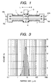
- FIG. 1 is a whole plan view of an embodiment of the variable resistor in accordance with the resistor to which the resistor described herein above is applied
- FIG. 2 is an exploded perspective view of the variable resister.
- the variable resistor comprises a frame 1 consisting of insulative material having U-shaped cross section having the open bottom end and open both side ends, an operation member 3 having a lever 2 that is to be operated externally, an insulative stopper plate 5 formed combinedly with a pair of sliders 4, and an insulating board 6.
- a resistor pattern 7 consisting of the resistor of the present invention formed by means of screen printing, a collector pattern 8 that extends along the resistor pattern 7, an input terminal 9a and an output terminal 9b that are connected to both ends of the resistor pattern 7, and an input terminal 10a and an output terminal 10b that are connected to both ends of the collector pattern 8 are formed.
- the insulating board 6 is contained in the frame 1, the operation member 3 and the stopper plate 5 are disposed with interposition of the insulating board 6 and the fame 1, the sliders 4 of the stopper plate 5 is mounted together so as to contact-slide with the resistor pattern 7 and the collector pattern 8 respectively in the arrow directions L and R shown in FIG. 1.
- the operation member 3 is slid in the arrow direction shown in FIG. 1 while a current and voltage is being applied between the input terminals 9a and 10a, the pair of sliders 4 are slid on the resistor pattern 7 and the collector pattern 8 concomitantly with the movement of the operation member 3.
- the conduction position between the pair of sliders 4 and the resistor pattern 7 and the collector pattern 8 varies, and the current and voltage output corresponding to the conduction position is obtained from the output terminals 9b and 10b.
- Example 1 of the resistor of the present invention the resistor that contains 20 % by volume of carbon black and 16 % by volume of carbon fiber were dispersed in acetylene-end polyisoimide resin that was served as the resistor base material.
- FIG. 3 is a graph for showing the particle size distribution of carbon fiber used in Example 1 observed by means of laser diffraction-diffusion method, the horizontal axis represents the particle size ( ⁇ m) and the vertical axis represents the proportion (% by volume) of the carbon fiber having the particle size at the position in the whole carbon fiber.
- the particle size distribution of carbon fiber used in Example 1 has a peak at a particle size of approximately 8 ⁇ m and 90 % by volume of carbon fiber is included in the particle size range from 5 to 13 ⁇ m.
- a commercially available carbon fiber was ground by means of jet mill grinding method, at that time the commercially available carbon fiber was charged at a rate of 1 to 3 g/min while compressed air of 6 to 7 kg/cm 2 was being fed at a rate of 0.2 to 0.6 m 3 /min into a cyclone having a diameter of 150 mm.
- the resistor used in Comparative example 1 contains 15 % by volume of carbon black and 16 % by volume of carbon fiber dispersed in the same resistor base material as used in Example 1.
- FIG. 9 is a graph having the same coordinate axis system as used in FIG. 3 for showing the particle size distribution of carbon fiber used in Comparative example 1.
- the particle size distribution of carbon fiber used in Comparative example 1 is not according to the normal distribution and asymmetrical, and 90 % by volume of carbon fiber is included in a particle size range of 50 ⁇ m.
- the resistor used in Comparative example 2 contains 20 % by volume of carbon black dispersed in the same resistor base material as used in Example 1.
- FIG. 4 shows the micro-linearity characteristic of Example 1.
- the horizontal axis of the graph shown in FIG. 4 represents the opening of a position sensor namely angle (degrees), and the vertical axis represents the micro-linearity (%).
- the micro-linearity characteristic of Comparative examples 1 and 2 are shown in FIG. 10 and FIG. 12 respectively.
- the horizontal axis and the vertical axis of FIG. 10 and FIG. 12 are the same as those of FIG. 4.
- FIG. 5 shows the wear resistance test result of Example 1.
- the horizontal axis of FIG. 5 represents the position of the resistor, and the vertical axis represents the wear depth ( ⁇ m) of the surface of the resistor. 0 ⁇ m of the vertical axis shows the resistor surface before wear resistance test.
- a six-component alloy brush was in contact with the resistor surface slidably, and the brush was reciprocated 400 million cycles, and then the wear of the resistor surface was observed by means of a needle contact surface roughness tester.
- the wear resistance test results of Comparative examples 1 and 2 are shown in FIG. 11 and FIG. 13 respectively.
- the horizontal axis and the vertical axis of FIG. 11 and FIG. 13 are the same as those of FIG. 4.
- Example 1 As obvious from the result described herein above, the wear resistance of Example 1 is improved significantly in comparison with Comparative example 2, and approximately equal to that of Comparative example 1 that contains much long length carbon fiber that is capable of distributing the load.
- the resistor contains 20 % by volume of carbon black and 20 % by volume of carbon fiber dispersed in the same resistor base material as used in Example 1.
- the particle size distribution of ground carbon fiber used in Example 2 is shown in the graph shown in FIG. 6, which has the same coordinate axes as shown in FIG. 3. As obvious from FIG. 6, the particle size distribution of the carbon fiber used in Example 2 has a peak at a particle size of approximately 2 ⁇ m and 90 % by volume of carbon fiber is included in the particulate size range from 1 to 3 ⁇ m.
- the carbon fiber used in Example 2 was obtained by grinding commercially available carbon fiber by means of a ball mill, at that time zirconia balls having the diameter from 5 to 10 mm were charged together with commercially available carbon fiber in a zirconia pot having a diameter of 100 to 200 mm and the ball mill was operated at a rotation speed of 60 to 150 rpm for 70 to 100 hr.
- micro-linearity characteristic of the resistor used in Example 2 is shown in FIG. 7 having the same coordinate axes as shown in FIG. 4. As obvious from FIG. 7, the micro-linearity characteristic shown in FIG. 7 is significantly improved in comparison with Comparative example 1, and approximately equal to that of Comparison example 2 involving the resistor that contains no carbon fiber.
- Example 2 The result of wear resistance test on Example 2 carried out under the same condition as applied in Example 1 is shown in FIG. 8 having the same coordinate axes as shown in FIG. 5.
- the wear resistance of Example 2 is significantly improved in comparison with Comparative example 2, and slightly inferior to Comparative example 1.
- the reason is likely that the long length carbon fiber contributes to distribution of the load for supporting in Comparative example 1, on the other hand the carbon fiber of Example 2 supports the load inferiorly due to granular configuration of the carbon fiber.
- the micro-linearity characteristic of Example 2 is significantly improved in comparison with Comparison example 1, the total performance is improved.
- carbon black and carbon fiber having a prescribed configuration are dispersed in resistor base material, the excellent wear resistance of carbon fiber is exhibited together with the excellent micro-linearity characteristic.
- variable resistor of the present invention uses the above-mentioned resistor of the present invention, the variable resistor has a desired micro-linearity characteristic and wear resistance. Because the performance is effective in a wide environmental temperature range, the variable resistor is suitably used for various sensors to be mounted on vehicles.
Landscapes
- Engineering & Computer Science (AREA)
- Microelectronics & Electronic Packaging (AREA)
- Adjustable Resistors (AREA)
Abstract
Description

On the other hand, the wear resistance test results of Comparative examples 1 and 2 are shown in FIG. 11 and FIG. 13 respectively. The horizontal axis and the vertical axis of FIG. 11 and FIG. 13 are the same as those of FIG. 4.
Claims (5)
- A resistor containing 15 to 20 % by volume of carbon black and 15 to 20 % by volume of carbon fiber in resistor base material, wherein the particle size distribution of the carbon fiber is approximately equal to the normal distribution and 80 % by volume or more carbon fiber of the whole carbon fiber is included in the particle size range from 1 to 20 µm.
- The resistor according to claim 1, wherein the particle size distribution of the carbon fiber has a peak in the particle size range from 1 to 3 µm.
- The resistor according to claim 1, wherein the particle size distribution of the carbon fiber has a peak in the particle size range from 6 to 10 µm.
- The resistor according to claim 1, 2 or 3, wherein the carbon fiber is subjected to coupling treatment with a coupling agent.
- A variable resistor that uses the resistor according to any preceding claim.
Applications Claiming Priority (2)
| Application Number | Priority Date | Filing Date | Title |
|---|---|---|---|
| JP14501199A JP3587730B2 (en) | 1999-05-25 | 1999-05-25 | Resistor and variable resistor using the resistor |
| JP14501199 | 1999-05-25 |
Publications (2)
| Publication Number | Publication Date |
|---|---|
| EP1056099A2 true EP1056099A2 (en) | 2000-11-29 |
| EP1056099A3 EP1056099A3 (en) | 2004-01-14 |
Family
ID=15375391
Family Applications (1)
| Application Number | Title | Priority Date | Filing Date |
|---|---|---|---|
| EP00303921A Withdrawn EP1056099A3 (en) | 1999-05-25 | 2000-05-10 | Resistor excellent in micro-linearity characteristic and wear resistance and variable resistor using the same |
Country Status (4)
| Country | Link |
|---|---|
| US (1) | US6172595B1 (en) |
| EP (1) | EP1056099A3 (en) |
| JP (1) | JP3587730B2 (en) |
| KR (1) | KR100340482B1 (en) |
Families Citing this family (7)
| Publication number | Priority date | Publication date | Assignee | Title |
|---|---|---|---|---|
| JP2002141210A (en) | 2000-10-31 | 2002-05-17 | Alps Electric Co Ltd | Resistor and variable resistor using the same |
| US6617377B2 (en) | 2001-10-25 | 2003-09-09 | Cts Corporation | Resistive nanocomposite compositions |
| JP4139126B2 (en) * | 2002-04-19 | 2008-08-27 | アルプス電気株式会社 | Resistor manufacturing method |
| JP3978380B2 (en) * | 2002-08-12 | 2007-09-19 | アルプス電気株式会社 | Variable resistor |
| US7141184B2 (en) | 2003-12-08 | 2006-11-28 | Cts Corporation | Polymer conductive composition containing zirconia for films and coatings with high wear resistance |
| US20060043343A1 (en) * | 2004-08-24 | 2006-03-02 | Chacko Antony P | Polymer composition and film having positive temperature coefficient |
| US20080282818A1 (en) * | 2007-05-17 | 2008-11-20 | Charles Smith | Sensors with nanoparticles |
Family Cites Families (7)
| Publication number | Priority date | Publication date | Assignee | Title |
|---|---|---|---|---|
| DE3916921C1 (en) * | 1989-05-24 | 1990-10-11 | Preh-Werke Gmbh & Co Kg, 8740 Bad Neustadt, De | |
| JPH03233904A (en) * | 1990-02-09 | 1991-10-17 | Alps Electric Co Ltd | Resistor for variable resistance |
| JPH0418703A (en) * | 1990-05-11 | 1992-01-22 | Nippon Teikouki Seisakusho:Kk | Resistance paste for slid resistor |
| US5111178A (en) * | 1990-06-15 | 1992-05-05 | Bourns, Inc. | Electrically conductive polymer thick film of improved wear characteristics and extended life |
| JP2889792B2 (en) * | 1993-07-01 | 1999-05-10 | アルプス電気株式会社 | Variable resistor |
| JP3372636B2 (en) * | 1994-03-16 | 2003-02-04 | アルプス電気株式会社 | Manufacturing method of resistive substrate |
| JPH10199704A (en) * | 1997-01-13 | 1998-07-31 | Denso Corp | Resistor for sliding resistor and method of manufacturing the same |
-
1999
- 1999-05-25 JP JP14501199A patent/JP3587730B2/en not_active Expired - Lifetime
-
2000
- 2000-05-10 EP EP00303921A patent/EP1056099A3/en not_active Withdrawn
- 2000-05-24 US US09/577,774 patent/US6172595B1/en not_active Expired - Lifetime
- 2000-05-24 KR KR1020000027943A patent/KR100340482B1/en not_active Expired - Lifetime
Also Published As
| Publication number | Publication date |
|---|---|
| US6172595B1 (en) | 2001-01-09 |
| JP3587730B2 (en) | 2004-11-10 |
| JP2000331806A (en) | 2000-11-30 |
| KR100340482B1 (en) | 2002-06-15 |
| KR20000077393A (en) | 2000-12-26 |
| EP1056099A3 (en) | 2004-01-14 |
Similar Documents
| Publication | Publication Date | Title |
|---|---|---|
| US5084211A (en) | Anisotropically electroconductive adhesive | |
| JP3986985B2 (en) | Pressure-sensitive resistor and pressure-sensitive sensor | |
| US6172595B1 (en) | Resistor excellent in micro-linearity characteristic and wear resistance and variable resistor using the same | |
| US5340641A (en) | Electrical overstress pulse protection | |
| JP4524745B2 (en) | Metal nanowire-containing conductive material and use thereof | |
| AU2001290266A1 (en) | Electroconductive metal paste and method for production thereof | |
| EP0401489B1 (en) | Electrostratic attracting sheet | |
| JP2010515239A (en) | Dielectric material with high aspect ratio particles switchable by voltage | |
| GB1561189A (en) | Pressure responsive electrically conductive elastomeric composition | |
| JP2005507146A (en) | Resistor nanocomposite composition | |
| CN107502066A (en) | A kind of graphene/metal nanobelt composite conducting ink and its preparation method and application | |
| US5820788A (en) | Electroconductive antistatic polymers containing carbonaceous fibers | |
| US5152650A (en) | Electrically conductive synthetic resin bolt | |
| Tchmutin et al. | Electrical transport in 0‐3 epoxy resin–barium titanate–carbon black polymer composites | |
| US4952158A (en) | Conductive board spacer | |
| JPH0311602A (en) | Resistance paste proper to manufacture of electric resistance layer and resistance layer manufactured from said resistance paste | |
| KR100418449B1 (en) | Resistor and variable resistor using the same | |
| EP1286336A3 (en) | Magnetic sensor, magnetic head and magnetic recording apparatus | |
| US5720622A (en) | Member for securing conduction and connector using the member | |
| JP3855410B2 (en) | Resistance paste, strain gauge using the same, and multidirectional operation body | |
| Mori et al. | Effects of the loadings and type of copper powder on the electrical resistivity of copper powder-polymer paint films | |
| JP3308358B2 (en) | Resistor paste | |
| US6815039B2 (en) | Resistance element for potentiometric devices, and method of manufacture | |
| JPH11269403A (en) | Carbon black and polymer composition thereof | |
| JPH06223615A (en) | Scaly ag-pt alloy conductive filler and its application |
Legal Events
| Date | Code | Title | Description |
|---|---|---|---|
| PUAI | Public reference made under article 153(3) epc to a published international application that has entered the european phase |
Free format text: ORIGINAL CODE: 0009012 |
|
| AK | Designated contracting states |
Kind code of ref document: A2 Designated state(s): AT BE CH CY DE DK ES FI FR GB GR IE IT LI LU MC NL PT SE |
|
| AX | Request for extension of the european patent |
Free format text: AL;LT;LV;MK;RO;SI |
|
| PUAL | Search report despatched |
Free format text: ORIGINAL CODE: 0009013 |
|
| AK | Designated contracting states |
Kind code of ref document: A3 Designated state(s): AT BE CH CY DE DK ES FI FR GB GR IE IT LI LU MC NL PT SE |
|
| AX | Request for extension of the european patent |
Extension state: AL LT LV MK RO SI |
|
| 17P | Request for examination filed |
Effective date: 20040130 |
|
| 17Q | First examination report despatched |
Effective date: 20040608 |
|
| AKX | Designation fees paid |
Designated state(s): DE FR GB |
|
| APBN | Date of receipt of notice of appeal recorded |
Free format text: ORIGINAL CODE: EPIDOSNNOA2E |
|
| APBR | Date of receipt of statement of grounds of appeal recorded |
Free format text: ORIGINAL CODE: EPIDOSNNOA3E |
|
| APAF | Appeal reference modified |
Free format text: ORIGINAL CODE: EPIDOSCREFNE |
|
| APBT | Appeal procedure closed |
Free format text: ORIGINAL CODE: EPIDOSNNOA9E |
|
| APBT | Appeal procedure closed |
Free format text: ORIGINAL CODE: EPIDOSNNOA9E |
|
| GRAP | Despatch of communication of intention to grant a patent |
Free format text: ORIGINAL CODE: EPIDOSNIGR1 |
|
| STAA | Information on the status of an ep patent application or granted ep patent |
Free format text: STATUS: THE APPLICATION IS DEEMED TO BE WITHDRAWN |
|
| 18D | Application deemed to be withdrawn |
Effective date: 20110120 |