EP1055856A2 - Pulse damper - Google Patents
Pulse damper Download PDFInfo
- Publication number
- EP1055856A2 EP1055856A2 EP00110402A EP00110402A EP1055856A2 EP 1055856 A2 EP1055856 A2 EP 1055856A2 EP 00110402 A EP00110402 A EP 00110402A EP 00110402 A EP00110402 A EP 00110402A EP 1055856 A2 EP1055856 A2 EP 1055856A2
- Authority
- EP
- European Patent Office
- Prior art keywords
- damper element
- pulse damper
- cylindrical wall
- layer
- region
- Prior art date
- Legal status (The legal status is an assumption and is not a legal conclusion. Google has not performed a legal analysis and makes no representation as to the accuracy of the status listed.)
- Withdrawn
Links
- 239000000446 fuel Substances 0.000 claims abstract description 26
- 238000002485 combustion reaction Methods 0.000 claims abstract description 11
- 238000013016 damping Methods 0.000 claims abstract description 3
- 239000010410 layer Substances 0.000 claims description 71
- 239000000463 material Substances 0.000 claims description 44
- 239000012530 fluid Substances 0.000 claims description 13
- 229930195733 hydrocarbon Natural products 0.000 claims description 5
- 150000002430 hydrocarbons Chemical class 0.000 claims description 5
- 239000004215 Carbon black (E152) Substances 0.000 claims description 4
- 239000002356 single layer Substances 0.000 claims description 4
- 230000004888 barrier function Effects 0.000 claims description 3
- 239000000203 mixture Substances 0.000 description 8
- 239000012815 thermoplastic material Substances 0.000 description 8
- KRHYYFGTRYWZRS-UHFFFAOYSA-M Fluoride anion Chemical compound [F-] KRHYYFGTRYWZRS-UHFFFAOYSA-M 0.000 description 6
- 229920002313 fluoropolymer Polymers 0.000 description 6
- 230000008901 benefit Effects 0.000 description 4
- 229920001577 copolymer Polymers 0.000 description 4
- 238000001125 extrusion Methods 0.000 description 4
- XUCNUKMRBVNAPB-UHFFFAOYSA-N fluoroethene Chemical compound FC=C XUCNUKMRBVNAPB-UHFFFAOYSA-N 0.000 description 4
- 239000004811 fluoropolymer Substances 0.000 description 4
- 238000000034 method Methods 0.000 description 4
- 230000008569 process Effects 0.000 description 4
- OKKJLVBELUTLKV-UHFFFAOYSA-N Methanol Chemical compound OC OKKJLVBELUTLKV-UHFFFAOYSA-N 0.000 description 3
- 239000004952 Polyamide Substances 0.000 description 3
- 238000004806 packaging method and process Methods 0.000 description 3
- 229920002647 polyamide Polymers 0.000 description 3
- 229920002620 polyvinyl fluoride Polymers 0.000 description 3
- CYXIKYKBLDZZNW-UHFFFAOYSA-N 2-Chloro-1,1,1-trifluoroethane Chemical compound FC(F)(F)CCl CYXIKYKBLDZZNW-UHFFFAOYSA-N 0.000 description 2
- OKTJSMMVPCPJKN-UHFFFAOYSA-N Carbon Chemical compound [C] OKTJSMMVPCPJKN-UHFFFAOYSA-N 0.000 description 2
- LFQSCWFLJHTTHZ-UHFFFAOYSA-N Ethanol Chemical compound CCO LFQSCWFLJHTTHZ-UHFFFAOYSA-N 0.000 description 2
- JHWNWJKBPDFINM-UHFFFAOYSA-N Laurolactam Chemical compound O=C1CCCCCCCCCCCN1 JHWNWJKBPDFINM-UHFFFAOYSA-N 0.000 description 2
- PXHVJJICTQNCMI-UHFFFAOYSA-N Nickel Chemical compound [Ni] PXHVJJICTQNCMI-UHFFFAOYSA-N 0.000 description 2
- 229920000299 Nylon 12 Polymers 0.000 description 2
- 229910052799 carbon Inorganic materials 0.000 description 2
- 239000006229 carbon black Substances 0.000 description 2
- 150000001875 compounds Chemical class 0.000 description 2
- 239000004020 conductor Substances 0.000 description 2
- 229920000578 graft copolymer Polymers 0.000 description 2
- 238000002347 injection Methods 0.000 description 2
- 239000007924 injection Substances 0.000 description 2
- 238000009434 installation Methods 0.000 description 2
- 239000000155 melt Substances 0.000 description 2
- 238000012986 modification Methods 0.000 description 2
- 230000004048 modification Effects 0.000 description 2
- 239000000178 monomer Substances 0.000 description 2
- 150000002978 peroxides Chemical class 0.000 description 2
- -1 polychlorotrifluoroethylene, ethylene tetrafluoroethylene copolymers Polymers 0.000 description 2
- 229920000642 polymer Polymers 0.000 description 2
- 230000035939 shock Effects 0.000 description 2
- JIAARYAFYJHUJI-UHFFFAOYSA-L zinc dichloride Chemical compound [Cl-].[Cl-].[Zn+2] JIAARYAFYJHUJI-UHFFFAOYSA-L 0.000 description 2
- 229920000049 Carbon (fiber) Polymers 0.000 description 1
- RYGMFSIKBFXOCR-UHFFFAOYSA-N Copper Chemical compound [Cu] RYGMFSIKBFXOCR-UHFFFAOYSA-N 0.000 description 1
- YCKRFDGAMUMZLT-UHFFFAOYSA-N Fluorine atom Chemical compound [F] YCKRFDGAMUMZLT-UHFFFAOYSA-N 0.000 description 1
- 229920000571 Nylon 11 Polymers 0.000 description 1
- 229920002292 Nylon 6 Polymers 0.000 description 1
- 239000004743 Polypropylene Substances 0.000 description 1
- XUIMIQQOPSSXEZ-UHFFFAOYSA-N Silicon Chemical compound [Si] XUIMIQQOPSSXEZ-UHFFFAOYSA-N 0.000 description 1
- BQCADISMDOOEFD-UHFFFAOYSA-N Silver Chemical compound [Ag] BQCADISMDOOEFD-UHFFFAOYSA-N 0.000 description 1
- 150000001298 alcohols Chemical class 0.000 description 1
- 150000007824 aliphatic compounds Chemical class 0.000 description 1
- 125000002947 alkylene group Chemical group 0.000 description 1
- 230000003466 anti-cipated effect Effects 0.000 description 1
- 150000001491 aromatic compounds Chemical class 0.000 description 1
- 238000005452 bending Methods 0.000 description 1
- 230000009286 beneficial effect Effects 0.000 description 1
- 239000004917 carbon fiber Substances 0.000 description 1
- UUAGAQFQZIEFAH-UHFFFAOYSA-N chlorotrifluoroethylene Chemical group FC(F)=C(F)Cl UUAGAQFQZIEFAH-UHFFFAOYSA-N 0.000 description 1
- 230000006835 compression Effects 0.000 description 1
- 238000007906 compression Methods 0.000 description 1
- 229910052802 copper Inorganic materials 0.000 description 1
- 239000010949 copper Substances 0.000 description 1
- 230000008878 coupling Effects 0.000 description 1
- 238000010168 coupling process Methods 0.000 description 1
- 238000005859 coupling reaction Methods 0.000 description 1
- 229920001971 elastomer Polymers 0.000 description 1
- 239000000806 elastomer Substances 0.000 description 1
- QHSJIZLJUFMIFP-UHFFFAOYSA-N ethene;1,1,2,2-tetrafluoroethene Chemical group C=C.FC(F)=C(F)F QHSJIZLJUFMIFP-UHFFFAOYSA-N 0.000 description 1
- 229920000840 ethylene tetrafluoroethylene copolymer Polymers 0.000 description 1
- 239000003063 flame retardant Substances 0.000 description 1
- 229910052731 fluorine Inorganic materials 0.000 description 1
- 239000011737 fluorine Substances 0.000 description 1
- PCHJSUWPFVWCPO-UHFFFAOYSA-N gold Chemical compound [Au] PCHJSUWPFVWCPO-UHFFFAOYSA-N 0.000 description 1
- 229910052737 gold Inorganic materials 0.000 description 1
- 239000010931 gold Substances 0.000 description 1
- 230000005484 gravity Effects 0.000 description 1
- 238000004519 manufacturing process Methods 0.000 description 1
- 229910052751 metal Inorganic materials 0.000 description 1
- 239000002184 metal Substances 0.000 description 1
- 150000002739 metals Chemical class 0.000 description 1
- 239000010705 motor oil Substances 0.000 description 1
- 229910052759 nickel Inorganic materials 0.000 description 1
- 229920003023 plastic Polymers 0.000 description 1
- 239000004033 plastic Substances 0.000 description 1
- 239000004014 plasticizer Substances 0.000 description 1
- 229920001155 polypropylene Polymers 0.000 description 1
- 239000000843 powder Substances 0.000 description 1
- 230000002265 prevention Effects 0.000 description 1
- 238000011084 recovery Methods 0.000 description 1
- 239000010703 silicon Substances 0.000 description 1
- 229910052710 silicon Inorganic materials 0.000 description 1
- 229910052709 silver Inorganic materials 0.000 description 1
- 239000004332 silver Substances 0.000 description 1
- 229910001220 stainless steel Inorganic materials 0.000 description 1
- 239000010935 stainless steel Substances 0.000 description 1
- 230000003068 static effect Effects 0.000 description 1
- 239000000126 substance Substances 0.000 description 1
- 229920001169 thermoplastic Polymers 0.000 description 1
- 229920002725 thermoplastic elastomer Polymers 0.000 description 1
- 239000004416 thermosoftening plastic Substances 0.000 description 1
- 238000011144 upstream manufacturing Methods 0.000 description 1
- 229960001939 zinc chloride Drugs 0.000 description 1
- 235000005074 zinc chloride Nutrition 0.000 description 1
- 239000011592 zinc chloride Substances 0.000 description 1
Images

Classifications
-
- F—MECHANICAL ENGINEERING; LIGHTING; HEATING; WEAPONS; BLASTING
- F02—COMBUSTION ENGINES; HOT-GAS OR COMBUSTION-PRODUCT ENGINE PLANTS
- F02M—SUPPLYING COMBUSTION ENGINES IN GENERAL WITH COMBUSTIBLE MIXTURES OR CONSTITUENTS THEREOF
- F02M37/00—Apparatus or systems for feeding liquid fuel from storage containers to carburettors or fuel-injection apparatus; Arrangements for purifying liquid fuel specially adapted for, or arranged on, internal-combustion engines
- F02M37/0011—Constructional details; Manufacturing or assembly of elements of fuel systems; Materials therefor
- F02M37/0041—Means for damping pressure pulsations
-
- F—MECHANICAL ENGINEERING; LIGHTING; HEATING; WEAPONS; BLASTING
- F16—ENGINEERING ELEMENTS AND UNITS; GENERAL MEASURES FOR PRODUCING AND MAINTAINING EFFECTIVE FUNCTIONING OF MACHINES OR INSTALLATIONS; THERMAL INSULATION IN GENERAL
- F16L—PIPES; JOINTS OR FITTINGS FOR PIPES; SUPPORTS FOR PIPES, CABLES OR PROTECTIVE TUBING; MEANS FOR THERMAL INSULATION IN GENERAL
- F16L55/00—Devices or appurtenances for use in, or in connection with, pipes or pipe systems
- F16L55/04—Devices damping pulsations or vibrations in fluids
-
- F—MECHANICAL ENGINEERING; LIGHTING; HEATING; WEAPONS; BLASTING
- F02—COMBUSTION ENGINES; HOT-GAS OR COMBUSTION-PRODUCT ENGINE PLANTS
- F02M—SUPPLYING COMBUSTION ENGINES IN GENERAL WITH COMBUSTIBLE MIXTURES OR CONSTITUENTS THEREOF
- F02M37/00—Apparatus or systems for feeding liquid fuel from storage containers to carburettors or fuel-injection apparatus; Arrangements for purifying liquid fuel specially adapted for, or arranged on, internal-combustion engines
- F02M37/0011—Constructional details; Manufacturing or assembly of elements of fuel systems; Materials therefor
- F02M37/0017—Constructional details; Manufacturing or assembly of elements of fuel systems; Materials therefor related to fuel pipes or their connections, e.g. joints or sealings
Definitions
- the invention is a pulse damper element for use to damp pulsating fluid flow and reduce pressure fluctuations in a fuel supply system for an internal combustion engine of a vehicle.
- Fuel supply systems for an internal combustion engines can produce resonance pressure fluctuations varying as wide as 5 psi to 90 psi.
- Internal combustion engines and especially those featuring fuel injectors require a stabilized pressure, usually nominally around 50-60 psi.
- Pulse damper elements have been used in the prior art to damp the pressure fluctuations. These damper elements are usually disposed in the fuel line adjacent to the internal combustion engine.
- the damper element of this disclosure includes a damper diaphragm which is fastened in a damper housing and defines a fluid chamber on one side.
- a connection fining is disposed on the damper housing and inserted into a plug connection from the fluid flow cross section.
- the flow opening and fluid flow cross section are penetrated by a flow tube arranged to protrude therethrough and into which a first fuel line, which discharges into the fluid chamber is embodied. Between the flow tube and the wall opening, an annular second fluid line is embodied.
- a damper element such as disclosed in the prior art requires a rigid housing to enclose a damper diaphragm.
- the rigid housing must be packaged for fit into a space limited engine compartment.
- the present invention is an improved pulse damper for placement in a fuel line for an internal combustion engine in motor vehicles.
- the improved pulse damper includes a multi-layer or single layer tubing having an elongated cylindrical wall having an outer surface and inner surface parallel to the outer surface. The inner surface defines an essentially unobstructed circular interior opening extending longitudinally through the tube.
- the tubing includes a first region in which the cylindrical wall is essentially parallel to the longitudinal axis running coaxially through the cylindrical interior.
- the tubing includes another region continuous to the first region, wherein the other region includes at least one corrugation in the cylindrical wall.
- the corrugated region has a cross sectional diameter which varies depending on position with respect to the corrugations longitudinal length and has a diameter different from the essentially uniform cross section diameter of the first region. The varying diameter of the corrugated region is preferably greater than the diameter of the first region.
- the convoluted or corrugated configuration of the tubular damper element of the subject invention dampens the resonance pressure fluctuation of the fluid passing through the system.
- the tubular damper element is particularly beneficial for use with a fuel supply system of an internal combustion engine when disposed adjacent to or approximate to the internal combustion engine.
- the pulse damper shown in Figure 6 is a single or multi-layer tube 10 having a corrugated region, wherein the tube 10 replaces the current damper housing with the internal diaphragm for placement upstream and adjacent to the engine.
- the tubing 10 is preferably multi-layer and is configured as disclosed in U.S. Patent Nos. 5,284,184 and 5,469,892 incorporated herein by reference.
- the multi-layer tubing as used in the subject invention may further include the material configurations as disclosed in U.S. Patent Nos. 5,524,673 and 5,566,720 also incorporated herein by reference.
- the tubing 10 of the present invention is defined by at least one corrugated region 12 located in its length to accommodate bending, flexing or twisting and further to damp the resonance frequency associated with fuel systems of internal combustion engines.
- the tubing 10 may also include a region 14 having an essentially uniform cross-section.
- the tubing 10 of the present invention may have an outer diameter up to 50mm. However, in application such as fuel lines and also in fluid recovery systems, outer diameters of up to 50.8mm (2 inches) are preferred.
- the tubing 10 may have any suitable wall thickness as desired. However, in automotive systems such as in the fluid lines, wall thicknesses between 0.5mm and 2.5mm are generally employed with wall thicknesses of approximately 2.0mm being preferred for fuel lines. While it is within the scope of this invention to use a corrugated tubing 10 for the pulse damp element having a plurality of overlaying thermoplastic materials, the tubing 10 of the present invention generally has a maximum of five layers inclusive of the bonding layers.
- the tubing of the present invention for the pulse damper element is made of a material which is suitable for use in motor vehicles and comprises a relatively thick outer layer which is nonreactive with the external environment and can withstand various shocks, vibrational fatigue and changes in temperature as well as exposure to various corrosive or degrative compounds to which it would be exposed through the normal course of operation of the motor vehicle.
- the tubing material will be discussed further hereinafter.
- the single or multi-layer tube of the present invention is composed of an elongated cylindrical wall 18 which preferably has an essentially circular cross-section perpendicular to its longitudinal axis.
- the cylindrical wall 18 has an essentially uniform wall thickness throughout its length in circumference and is defined by an inner surface and an opposed outer surface.
- the inner surface defines an essentially cylindrical opening which extends longitudinally through the tubing of the present invention essentially coaxial to the longitudinal axis.
- the cylindrical wall 18 of the multi-layer or singular tube comprises at least two distinct regions.
- the cylindrical wall has a first region 14 where the cylindrical wall 18 is essentially parallel to the longitudinal axis. Contiguous to the first region 14 is a second region 12 which is defined by at least one convolution 12 or corrugation in the cylindrical wall 18.
- the term convolution is defined as an area of cylindrical wall which deviates from parallel to the longitudinal axis. This deviation can produce inner diameter which is between about 20 percent and 300 percent greater than the inner diameter of the first region at its maximum. In the preferred embodiment, the inner diameter of convolution is between 20 percent and 100 percent greater than the inner diameter of the first region 14.
- the tubing configuration of the pulse damper of the present invention can have as many convolutions with any length of cylindrical tubing optionally interposed therebetween as would be necessary to accommodate varying engine requirements and packaging requirement.
- the geometry of the convolutions can be of any cross-sectional profile desired.
- the convolutions may have angled, squared or sinusoidal profiles as desired.
- the pulse damper 10 of the present invention may be installed in the fuel line adjacent to the feed to the engine by connection means such as disclosed in U.S. Patent No. 5,090,745 and incorporated herein by reference.
- the connection means may include a compression sleeve 16 made of plastic material which does not relax at high temperatures such as 350°F so that a compressive pressure is maintained on the end of the tubular pulse damper 10 at elevated temperatures.
- Other conventional connection means that provide operative coupling to the fuel line may also be employed.
- the tubing may be a mono- wall tubing or a multi-layer tubing.
- a multi-layer tubing provides added advantages when carrying fuel in a fuel injection system.
- a typical mono-walled tubing 10, as shown in Figure 1, would have a single layer 20 constructed from a material such as a polyamide, such as Nylon 12, which provides a cold impact resistance of at least 2 foot pounds at -20°C.
- the tube 10 of the second embodiment of the present invention is suitable for use at an outer surface temperature range of about -40°C. and about 150°C., with a range of -20°C. being preferred.
- the tube 10 according to the second embodiment will have a tensile strength of no less than 15 N/mm 2 and an elongation value of at least 150% at 23°C.
- the tube 10 of the second embodiment has a burst strength at 23°C. and 120°C. of at least 20 bar and is sufficiently resistant to exposure to break fluid, engine oil and peroxides such as those which may be found in gasoline.
- the layer 22 is positioned radially innermost of all succeeding layers.
- the inner layer 22 has an inner surface 28 oriented to come into direct contact with the fuel or gaseous material conveyed through the tube 10.
- the inner layer 22 is composed of a thermoplastic fluoropolymer which exhibits resistance to the components contained in conventional gasoline fuel mixtures including, but not limited to, alcohols such as methanol and ethanol, peroxides, short-chain hydrocarbons and the like.
- the fluoropolymer of choice employed in the present invention has a melt temperature between about 160° and 200°C.; and a melt temperature between about 165° and 180°C. being most preferred.
- the specific gravity of material employed in the first inner layer 12 is, between 1.95 and 1.98.
- the preferred fluoropolymer is a multi-component system having as its three major components an alkylene fluoropolymer, a material made from a fluoro-olefin monomer or monomers and a vinyl fluoride material. Such materials are reacted by a suitable process to form a terpolymeric material.
- Various terpolymeric materials are commercially available for use in coextrusion processes to form the tube 10 of the present invention. Selection of such material suitable for use would be within the purview of the skilled artisan after reading this disclosure.
- the outer layer 24, and in particular, the outwardly oriented surface 26 is essentially non-reactive with the external environment and can withstand various shocks, vibrational fatigue, and changes in temperature as well as exposure to various corrosive compounds to which it would be exposed through the normal course of operation of the vehicle.
- the inner layer 34 is integrally bonded to the inner surface of the thick outer polyamide layer 32.
- the inner layer 34 is a chemically dissimilar, permeation resistant, chemical resistant, fuel resistant thermoplastic material which is melt processible in normal ranges of extrusion, i.e. about 175°C. to about 250°C.
- chemically dissimilar it is meant that the inner layer 34 consists essentially of a non-polyamide material which is capable of adhesion to a bonding layer 36 interposed between the thick outer layer 32 and the inner layer 34 in a manner which will be described subsequently.
- the thermoplastic material which comprises the inner layer 34 is a fluoroplastic material selected from the group consisting of a polyvinylidine fluoride, polyvinyl fluoride, polychlorotrifluoroethylene, ethylene tetrafluoroethylene copolymers, a graft copolymer of the preceding materials together with a fluoride-containing polymer such as copolymers of vinylidine fluoride and chlorotrifluoroethane, and mixtures thereof.
- a fluoroplastic material selected from the group consisting of a polyvinylidine fluoride, polyvinyl fluoride, polychlorotrifluoroethylene, ethylene tetrafluoroethylene copolymers, a graft copolymer of the preceding materials together with a fluoride-containing polymer such as copolymers of vinylidine fluoride and chlorotrifluoroethane, and mixtures thereof.
- Other material may be used for the inner layer 34 which is a fluoro
- the tubing 10 of the present invention may also, optionally include an outer jacket or fourth layer 38 which surrounds the outer or third layer 32.
- the jacket 38 may be either co-extruded with the other layers during the extrusion process or may be put on in a subsequent process such as cross-extrusion.
- the outer jacket 38 may be made of any material chosen for its structural or insulating characteristics and may be of any suitable wall thickness.
- the outer jacket 38 may be made of a thermoplastic material selected from the group consisting of zinc-chloride resistant Nylon 6, Nylon 11, Nylon 12, polypropylene, and thermoplastic elastomers. If desired, these materials may be modified to include flame retardants, plasticizers, and the like.
- the outer jacket 38 may, preferably, exhibit conductive characteristics in that it is capable of dissipation of electrostatic charge within a predetermined range.
- the material which composes the outer jacket 38 may be inherently conductive in these ranges or, preferably, include in its composition a conductive media in sufficient quantity to permit electrostatic dissipation in the predetermined range.
- the conductive media may be any suitable material of a composition and shape capable of effecting this static dissipation.
- the conductive material may be selected from the group consisting of elemental carbon, stainless steel, highly conductive metals such as copper, silver, gold, nickel and silicon, and mixtures thereof.
- the term "elemental carbon” as used herein is employed to describe and include materials commonly referred to as "carbon black.”
- the carbon black can be present in the form of carbon fibers, powders, spheres, and the like.
- the inner layer 34 of the present invention may include an innermost electrostatic dissipation sub-layer 42 which is also capable of serving as a hydrocarbon barrier to assist in the prevention of permeation of aromatic and aliphatic compounds found in gasoline through to the outer layer 32 of the tubing 10 and, thus, out to the surrounding environment.
- an innermost electrostatic dissipation sub-layer 42 which is also capable of serving as a hydrocarbon barrier to assist in the prevention of permeation of aromatic and aliphatic compounds found in gasoline through to the outer layer 32 of the tubing 10 and, thus, out to the surrounding environment.
- the electrostatic dissipation sub-layer 42 of the inner layer 34 may be integrally bonded to the inner surface of an optional sub-layer 40 disposed between sub-layer 42 and the intermediate bonding layer 36.
- the sub-layers 40 and 42 are chemically similar materials in structure and composition.
- the term "chemically similar material” is defined as a thermoplastic material selected from the group consisting of polyvinylidine fluoride, polyvinyl fluoride, a graft copolymer of the preceding materials together with a fluorine-containing polymer such a copolymers of vinylidine fluoride and chlorotrifluoroethane, a copolymer of a vinyl fluoride and chlorotrifluoroethylene, the vinyl fluoride material selected from the group consisting of polyvinylidine fluoride, polyvinyl fluoride, and mixtures thereof; a copolymer of vinyl fluoride material and ethylene tetrafluoroethylene; and a non-fluorinated elastomer, and mixtures thereof.
- the sub-layers 40 and 42 are composed of the same material, with the exception of the electrostatic dissipation sub-layer 42 including additional conductive material as described hereinafter.
- the sub-layers 40 and 42, intermediate bonding layer 36, outer layer 32 and jacket 38 define a five layer tubing 10.
- the inner layer 34 is composed of a thermoplastic material chemically dissimilar to the thermoplastic material employed in the outer layer 32 which is melt-processible in the normal ranges of extrusion, i.e. about 175°C. to about 250°C.
- the thermoplastic material employed in the inner layer 34 is capable of sufficiently permanent laminar adhesion to the intermediate bonding layer 36.
- the material according to the fifth embodiment also contains conductive media in quantities sufficient to permit electrostatic dissipation in a desired range.
- the electrostatic dissipation sub-layer 42 of the inner layer 34 exhibits electrostatic conductive characteristics capable of dissipating electrostatic charges in the desired range. Further details of the electrostatic dissipation sub-layer 42 are detailed in U.S. Patent No. 5,524,673.
- the inner layer 34 is maintained at a thickness suitable to achieve a hydrocarbon permeation value for the tubing 10 of the present invention no greater than about 0.5 g/m 2 in a 24 hour interval.
- the characteristics of the inner layer 34 can be relied upon solely or in concert with the intermediate bonding layer 36. It is anticipated that the thickness of the inner layer 34 and the intermediate layer 36 can be modified to accomplish this end.
- Other materials with their characteristics and advantages that are envisioned for use in the pulse damper element of the present invention are detailed in the patents incorporated herein by reference.
- the present invention provides a mono or multi-layer tubing having a convoluted region for use as a damper element.
- the subject damper element can accommodate the introduction of various bends and contours during installation.
- the material is fuel resistant to fuel permeation and can permit dissipation of electrostatic discharge.
- the mono or multi-layer tubing having a convoluted region can be used as a damper element for other fluids and in other environments.
Landscapes
- Engineering & Computer Science (AREA)
- General Engineering & Computer Science (AREA)
- Mechanical Engineering (AREA)
- Chemical & Material Sciences (AREA)
- Combustion & Propulsion (AREA)
- Fuel-Injection Apparatus (AREA)
- Fluidized-Bed Combustion And Resonant Combustion (AREA)
Abstract
Description
- The invention is a pulse damper element for use to damp pulsating fluid flow and reduce pressure fluctuations in a fuel supply system for an internal combustion engine of a vehicle.
- Fuel supply systems for an internal combustion engines can produce resonance pressure fluctuations varying as wide as 5 psi to 90 psi. Internal combustion engines and especially those featuring fuel injectors require a stabilized pressure, usually nominally around 50-60 psi. Pulse damper elements have been used in the prior art to damp the pressure fluctuations. These damper elements are usually disposed in the fuel line adjacent to the internal combustion engine.
- One such damping element is disclosed in U.S. Patent No. 4,615,320 issued to Fehrenbach et al. on October 7, 1986. The damper element of this disclosure includes a damper diaphragm which is fastened in a damper housing and defines a fluid chamber on one side. A connection fining is disposed on the damper housing and inserted into a plug connection from the fluid flow cross section. The flow opening and fluid flow cross section are penetrated by a flow tube arranged to protrude therethrough and into which a first fuel line, which discharges into the fluid chamber is embodied. Between the flow tube and the wall opening, an annular second fluid line is embodied.
- A damper element such as disclosed in the prior art requires a rigid housing to enclose a damper diaphragm. The rigid housing must be packaged for fit into a space limited engine compartment.
- Therefore, it is desirable to provide a pulse damper element which requires smaller packaging and more flexibility for installation into an engine compartment.
- The present invention is an improved pulse damper for placement in a fuel line for an internal combustion engine in motor vehicles. The improved pulse damper includes a multi-layer or single layer tubing having an elongated cylindrical wall having an outer surface and inner surface parallel to the outer surface. The inner surface defines an essentially unobstructed circular interior opening extending longitudinally through the tube. The tubing includes a first region in which the cylindrical wall is essentially parallel to the longitudinal axis running coaxially through the cylindrical interior. The tubing includes another region continuous to the first region, wherein the other region includes at least one corrugation in the cylindrical wall. The corrugated region has a cross sectional diameter which varies depending on position with respect to the corrugations longitudinal length and has a diameter different from the essentially uniform cross section diameter of the first region. The varying diameter of the corrugated region is preferably greater than the diameter of the first region.
- The convoluted or corrugated configuration of the tubular damper element of the subject invention dampens the resonance pressure fluctuation of the fluid passing through the system. The tubular damper element is particularly beneficial for use with a fuel supply system of an internal combustion engine when disposed adjacent to or approximate to the internal combustion engine.
- Other objects, advantages and applications of the present invention will become apparent to those skilled in the art when the following description of the best mode contemplated for practicing the invention is read in conjunction with the accompanying drawings.
- The description herein makes reference to the accompanying drawings wherein like reference numerals refer to like parts throughout the several views, and wherein:
- Figure 1
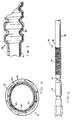
- is a sectional view through a piece of a tubular pulse damper of the present invention having a single layer of material;
- Figure 2
- is a sectional view through a piece of the tubular pulse damper having two layers of material;
- Figure 3
- is a sectional view through a piece of the tubular pulse damper having three layers of material;
- Figure 4
- is a sectional view through a piece of the tubular pulse damper having four layers of material;
- Figure 5
- is a sectional view through a piece of the tubular pulse damper having five layers of material;
- Figure 6
- is a side view of the tubular pulse damper; and
- Figure 7
- is a sectional side view of a portion of the tubular pulse damper having multiple layers of material.
- The pulse damper shown in Figure 6 is a single or
multi-layer tube 10 having a corrugated region, wherein thetube 10 replaces the current damper housing with the internal diaphragm for placement upstream and adjacent to the engine. Thetubing 10 is preferably multi-layer and is configured as disclosed in U.S. Patent Nos. 5,284,184 and 5,469,892 incorporated herein by reference. The multi-layer tubing as used in the subject invention may further include the material configurations as disclosed in U.S. Patent Nos. 5,524,673 and 5,566,720 also incorporated herein by reference. - The
tubing 10 of the present invention is defined by at least onecorrugated region 12 located in its length to accommodate bending, flexing or twisting and further to damp the resonance frequency associated with fuel systems of internal combustion engines. Thetubing 10 may also include aregion 14 having an essentially uniform cross-section. Thetubing 10 of the present invention may have an outer diameter up to 50mm. However, in application such as fuel lines and also in fluid recovery systems, outer diameters of up to 50.8mm (2 inches) are preferred. - The
tubing 10 may have any suitable wall thickness as desired. However, in automotive systems such as in the fluid lines, wall thicknesses between 0.5mm and 2.5mm are generally employed with wall thicknesses of approximately 2.0mm being preferred for fuel lines. While it is within the scope of this invention to use acorrugated tubing 10 for the pulse damp element having a plurality of overlaying thermoplastic materials, thetubing 10 of the present invention generally has a maximum of five layers inclusive of the bonding layers. - The tubing of the present invention for the pulse damper element is made of a material which is suitable for use in motor vehicles and comprises a relatively thick outer layer which is nonreactive with the external environment and can withstand various shocks, vibrational fatigue and changes in temperature as well as exposure to various corrosive or degrative compounds to which it would be exposed through the normal course of operation of the motor vehicle. The tubing material will be discussed further hereinafter.
- The single or multi-layer tube of the present invention is composed of an elongated
cylindrical wall 18 which preferably has an essentially circular cross-section perpendicular to its longitudinal axis. Thecylindrical wall 18 has an essentially uniform wall thickness throughout its length in circumference and is defined by an inner surface and an opposed outer surface. The inner surface defines an essentially cylindrical opening which extends longitudinally through the tubing of the present invention essentially coaxial to the longitudinal axis. - In the preferred embodiment, the
cylindrical wall 18 of the multi-layer or singular tube comprises at least two distinct regions. The cylindrical wall has afirst region 14 where thecylindrical wall 18 is essentially parallel to the longitudinal axis. Contiguous to thefirst region 14 is asecond region 12 which is defined by at least oneconvolution 12 or corrugation in thecylindrical wall 18. As used herein, the term convolution is defined as an area of cylindrical wall which deviates from parallel to the longitudinal axis. This deviation can produce inner diameter which is between about 20 percent and 300 percent greater than the inner diameter of the first region at its maximum. In the preferred embodiment, the inner diameter of convolution is between 20 percent and 100 percent greater than the inner diameter of thefirst region 14. - The tubing configuration of the pulse damper of the present invention can have as many convolutions with any length of cylindrical tubing optionally interposed therebetween as would be necessary to accommodate varying engine requirements and packaging requirement. The geometry of the convolutions can be of any cross-sectional profile desired. Thus the convolutions may have angled, squared or sinusoidal profiles as desired. The
pulse damper 10 of the present invention may be installed in the fuel line adjacent to the feed to the engine by connection means such as disclosed in U.S. Patent No. 5,090,745 and incorporated herein by reference. The connection means may include a compression sleeve 16 made of plastic material which does not relax at high temperatures such as 350°F so that a compressive pressure is maintained on the end of thetubular pulse damper 10 at elevated temperatures. Other conventional connection means that provide operative coupling to the fuel line may also be employed. - Testing has determined that when the
convoluted tubing section 12 is placed just before the fuel feed to the engine, the resonance pressure fluctuation that may normally vary from 5psi to 90psi is damped to a nominal pressure of 50-60psi. Various lengths ofconvoluted tubing 12 placed in the fuel injection system prior to the fuel feed to the engine provided similar results. Therefore, the length of the convoluted tubing is primarily controlled by the underhood engine packaging requirements. One advantage of using atube 10 having aconvoluted region 12 as the pulse damper element includes less joints for connection than is required in the housing diaphragm of the prior art. In addition, thetube 10 of the present invention is less weight and is less costly to manufacture, assemble, and package into the vehicle. Further, after its use, the tube material can be recycled. - As discussed supra, the tubing may be a mono- wall tubing or a multi-layer tubing. A multi-layer tubing provides added advantages when carrying fuel in a fuel injection system. A typical mono-
walled tubing 10, as shown in Figure 1, would have a single layer 20 constructed from a material such as a polyamide, such asNylon 12, which provides a cold impact resistance of at least 2 foot pounds at -20°C. - The
tube 10 of the second embodiment of the present invention, composed of theinner layer 22 and theouter layer 24 as shown in Figure 2, is suitable for use at an outer surface temperature range of about -40°C. and about 150°C., with a range of -20°C. being preferred. Thetube 10 according to the second embodiment will have a tensile strength of no less than 15 N/mm2 and an elongation value of at least 150% at 23°C. Thetube 10 of the second embodiment has a burst strength at 23°C. and 120°C. of at least 20 bar and is sufficiently resistant to exposure to break fluid, engine oil and peroxides such as those which may be found in gasoline. - In the second embodiment, the
layer 22 is positioned radially innermost of all succeeding layers. Theinner layer 22 has an inner surface 28 oriented to come into direct contact with the fuel or gaseous material conveyed through thetube 10. Theinner layer 22 is composed of a thermoplastic fluoropolymer which exhibits resistance to the components contained in conventional gasoline fuel mixtures including, but not limited to, alcohols such as methanol and ethanol, peroxides, short-chain hydrocarbons and the like. The fluoropolymer of choice employed in the present invention has a melt temperature between about 160° and 200°C.; and a melt temperature between about 165° and 180°C. being most preferred. The specific gravity of material employed in the firstinner layer 12 is, between 1.95 and 1.98. The preferred fluoropolymer is a multi-component system having as its three major components an alkylene fluoropolymer, a material made from a fluoro-olefin monomer or monomers and a vinyl fluoride material. Such materials are reacted by a suitable process to form a terpolymeric material. Various terpolymeric materials are commercially available for use in coextrusion processes to form thetube 10 of the present invention. Selection of such material suitable for use would be within the purview of the skilled artisan after reading this disclosure. - The
outer layer 24, and in particular, the outwardly oriented surface 26 is essentially non-reactive with the external environment and can withstand various shocks, vibrational fatigue, and changes in temperature as well as exposure to various corrosive compounds to which it would be exposed through the normal course of operation of the vehicle. - In the third, fourth and fifth embodiments of the present invention (Figures 3, 4 and 5 respectively), the
inner layer 34 is integrally bonded to the inner surface of the thickouter polyamide layer 32. In the present invention, theinner layer 34 is a chemically dissimilar, permeation resistant, chemical resistant, fuel resistant thermoplastic material which is melt processible in normal ranges of extrusion, i.e. about 175°C. to about 250°C. By the term "chemically dissimilar" it is meant that theinner layer 34 consists essentially of a non-polyamide material which is capable of adhesion to abonding layer 36 interposed between the thickouter layer 32 and theinner layer 34 in a manner which will be described subsequently. - In each of the embodiments, the thermoplastic material which comprises the
inner layer 34 is a fluoroplastic material selected from the group consisting of a polyvinylidine fluoride, polyvinyl fluoride, polychlorotrifluoroethylene, ethylene tetrafluoroethylene copolymers, a graft copolymer of the preceding materials together with a fluoride-containing polymer such as copolymers of vinylidine fluoride and chlorotrifluoroethane, and mixtures thereof. Other material may be used for theinner layer 34 which is a fluoroplastic material as detailed in U.S. Patent No. 5,524,673. - In any of the disclosed embodiments, the
tubing 10 of the present invention may also, optionally include an outer jacket orfourth layer 38 which surrounds the outer orthird layer 32. Thejacket 38 may be either co-extruded with the other layers during the extrusion process or may be put on in a subsequent process such as cross-extrusion. Theouter jacket 38 may be made of any material chosen for its structural or insulating characteristics and may be of any suitable wall thickness. In the preferred embodiment, theouter jacket 38 may be made of a thermoplastic material selected from the group consisting of zinc-chloride resistant Nylon 6, Nylon 11,Nylon 12, polypropylene, and thermoplastic elastomers. If desired, these materials may be modified to include flame retardants, plasticizers, and the like. - In the third, fourth and fifth embodiments of the invention, the
outer jacket 38 may, preferably, exhibit conductive characteristics in that it is capable of dissipation of electrostatic charge within a predetermined range. The material which composes theouter jacket 38 may be inherently conductive in these ranges or, preferably, include in its composition a conductive media in sufficient quantity to permit electrostatic dissipation in the predetermined range. The conductive media may be any suitable material of a composition and shape capable of effecting this static dissipation. The conductive material may be selected from the group consisting of elemental carbon, stainless steel, highly conductive metals such as copper, silver, gold, nickel and silicon, and mixtures thereof. The term "elemental carbon" as used herein is employed to describe and include materials commonly referred to as "carbon black." The carbon black can be present in the form of carbon fibers, powders, spheres, and the like. - The
inner layer 34 of the present invention according to the fifth embodiment, as illustrated in FIG. 5, may include an innermostelectrostatic dissipation sub-layer 42 which is also capable of serving as a hydrocarbon barrier to assist in the prevention of permeation of aromatic and aliphatic compounds found in gasoline through to theouter layer 32 of thetubing 10 and, thus, out to the surrounding environment. - In the fifth embodiment, the
electrostatic dissipation sub-layer 42 of theinner layer 34 may be integrally bonded to the inner surface of anoptional sub-layer 40 disposed betweensub-layer 42 and theintermediate bonding layer 36. Preferably, the sub-layers 40 and 42 are chemically similar materials in structure and composition. As used here, the term "chemically similar material" is defined as a thermoplastic material selected from the group consisting of polyvinylidine fluoride, polyvinyl fluoride, a graft copolymer of the preceding materials together with a fluorine-containing polymer such a copolymers of vinylidine fluoride and chlorotrifluoroethane, a copolymer of a vinyl fluoride and chlorotrifluoroethylene, the vinyl fluoride material selected from the group consisting of polyvinylidine fluoride, polyvinyl fluoride, and mixtures thereof; a copolymer of vinyl fluoride material and ethylene tetrafluoroethylene; and a non-fluorinated elastomer, and mixtures thereof. Preferably, the sub-layers 40 and 42 are composed of the same material, with the exception of theelectrostatic dissipation sub-layer 42 including additional conductive material as described hereinafter. The sub-layers 40 and 42,intermediate bonding layer 36,outer layer 32 andjacket 38 define a fivelayer tubing 10. In the third, fourth and fifth embodiments, theinner layer 34 is composed of a thermoplastic material chemically dissimilar to the thermoplastic material employed in theouter layer 32 which is melt-processible in the normal ranges of extrusion, i.e. about 175°C. to about 250°C. The thermoplastic material employed in theinner layer 34 is capable of sufficiently permanent laminar adhesion to theintermediate bonding layer 36. - The material according to the fifth embodiment, also contains conductive media in quantities sufficient to permit electrostatic dissipation in a desired range. In the fifth embodiment, the
electrostatic dissipation sub-layer 42 of theinner layer 34 exhibits electrostatic conductive characteristics capable of dissipating electrostatic charges in the desired range. Further details of theelectrostatic dissipation sub-layer 42 are detailed in U.S. Patent No. 5,524,673. - In the third, fourth and fifth embodiments, the
inner layer 34 is maintained at a thickness suitable to achieve a hydrocarbon permeation value for thetubing 10 of the present invention no greater than about 0.5 g/m2 in a 24 hour interval. To accomplish this, the characteristics of theinner layer 34 can be relied upon solely or in concert with theintermediate bonding layer 36. It is anticipated that the thickness of theinner layer 34 and theintermediate layer 36 can be modified to accomplish this end. Other materials with their characteristics and advantages that are envisioned for use in the pulse damper element of the present invention are detailed in the patents incorporated herein by reference. - Thus, the present invention provides a mono or multi-layer tubing having a convoluted region for use as a damper element. The subject damper element can accommodate the introduction of various bends and contours during installation. The material is fuel resistant to fuel permeation and can permit dissipation of electrostatic discharge. Although described in the environment of a damper element for a fuel supply system, it is envisioned that the mono or multi-layer tubing having a convoluted region can be used as a damper element for other fluids and in other environments.
- While the invention has been described in connection with what is presently considered to be the most practical and preferred embodiment, it is to be understood that the invention is not to be limited to the disclosed embodiments but, on the contrary, is intended to cover various modifications and equivalent arrangements included within the spirit and scope of the appended claims, which scope is to be accorded the broadest interpretation so as to encompass all such modifications and equivalent structures as is permitted under the law.
Claims (19)
- A pulse damper element for damping resonance pressure fluctuations in a fuel supply system for an internal combustion engine of a vehicle comprising:a tubing (10) having a first and second region (14,12), the first region (14) having, an essentially uniform cross-sectional diameter and the second region (12) having a cross-sectional diameter which varies positionally depending on longitudinal location in the second region.
- The pulse dampener of element of claim 1, wherein the tubing has a cylindrical wall (18) defining the cross-sectional diameter of the tubing and wherein the thickness of the cylindrical wall is essentially uniform along its longitudinal length.
- The pulse damper element of claim 2, wherein the cylindrical wall has a single layer (20) of material.
- The pulse damper element of claim 2, wherein the cylindrical wall has multi-layers of material (22, 24; 32, 34, 36; 38; 40).
- The pulse damper element of claim 2, wherein the cylindrical wall (18) has at least one convolution.
- The pulse damper element of claim 5, wherein the cross-sectional diameter of the convolution is between approximately 20% and 300% greater than the cross-sectional diameter of the first region (14).
- The pulse damper element of claim 5, wherein the convolution has one of an angled, squared and sinusoidal longitudinal cross-sectional profile.
- The pulse damper element of claim 5, wherein the cylindrical wall has an outer surface and an inner surface, wherein the outer surface is parallel with the inner surface.
- The pulse damper element of at least one of claims 4 to 8, wherein the outer layer has conductive characteristics for dissipating electrostatic charge.
- The pulse damper element of at least one of claims 4 to 8, wherein an inner layer of the cylindrical wall has conductive characteristics for dissipating electrostatic charge.
- The pulse damper element of at least one of claims 4 to 10, wherein at least one layer of material serves as a hydrocarbon barrier.
- The pulse damper element of claim 1, further including connection means (16) for connecting the pulse damper element in the fuel supply system proximate to the internal combustion engine.
- A pulse damper element for a fluid passage system in a vehicle comprising: a tubing (10) having a cylindrical wall (18) wherein the cylindrical wall has at least one convolution.
- The pulse damper element of claim 13, wherein said cylindrical wall has multi-layers of material (22, 24; 32, 34, 36; 38; 40)..
- The pulse damper element of claim 14, wherein at least one layer of material of the cylindrical wall has conductive characteristics for dissipating electrostatic charge.
- The pulse damper element of claim 14, wherein at least one layer serves as a hydrocarbon barrier.
- The pulse damper element of claim 13, wherein the convolution has one of an angled, squared, and sinusoidal longitudinal cross-sectional profile.
- The pulse damper element of claim 14, wherein the convolution has one of an angled, squared, and sinusoidal longitudinal cross-sectional profile.
- The pulse damper element of claim 13, further comprising connection means for securely connecting the pulse damper element in the fluid passage system.
Applications Claiming Priority (2)
| Application Number | Priority Date | Filing Date | Title |
|---|---|---|---|
| US32128399A | 1999-05-27 | 1999-05-27 | |
| US321283 | 1999-05-27 |
Publications (2)
| Publication Number | Publication Date |
|---|---|
| EP1055856A2 true EP1055856A2 (en) | 2000-11-29 |
| EP1055856A3 EP1055856A3 (en) | 2001-08-16 |
Family
ID=23249959
Family Applications (1)
| Application Number | Title | Priority Date | Filing Date |
|---|---|---|---|
| EP00110402A Withdrawn EP1055856A3 (en) | 1999-05-27 | 2000-05-16 | Pulse damper |
Country Status (1)
| Country | Link |
|---|---|
| EP (1) | EP1055856A3 (en) |
Cited By (3)
| Publication number | Priority date | Publication date | Assignee | Title |
|---|---|---|---|---|
| WO2001068397A1 (en) * | 2000-03-15 | 2001-09-20 | Salflex Polymers Ltd. | Flexible fuel filler pipe |
| EP1443205A3 (en) * | 2003-01-29 | 2008-02-27 | Hitachi, Ltd. | Fuel supply system for internal combustion engine and fuel transfer tube |
| EP2412964A1 (en) * | 2010-07-26 | 2012-02-01 | Continental Automotive GmbH | Corrugated pipe of a fuel line |
Citations (2)
| Publication number | Priority date | Publication date | Assignee | Title |
|---|---|---|---|---|
| US4615320A (en) | 1983-07-27 | 1986-10-07 | Robert Bosch Gmbh | Damper element |
| US5524673A (en) | 1992-04-14 | 1996-06-11 | Itt Corporation | Multi-layer tubing having electrostatic dissipation for handling hydrocarbon fluids |
Family Cites Families (5)
| Publication number | Priority date | Publication date | Assignee | Title |
|---|---|---|---|---|
| FR2596490B1 (en) * | 1986-03-28 | 1989-04-28 | Ouest Cie | FLEXIBLE PIPES FOR THE TRANSPORT OF PRESSURIZED OR PRESSURIZED FLUIDS, ESPECIALLY FOR MOTOR VEHICLE ENGINES |
| IT1264044B (en) * | 1993-02-04 | 1996-09-09 | CONVEYOR SLEEVE. | |
| JPH07260084A (en) * | 1994-03-16 | 1995-10-13 | Tokai Rubber Ind Ltd | Pulsation absorber |
| JPH08261101A (en) * | 1995-03-28 | 1996-10-08 | Toyoda Gosei Co Ltd | Fuel pressure pulsation damping device |
| JP3649862B2 (en) * | 1997-06-23 | 2005-05-18 | 本田技研工業株式会社 | Fuel piping structure |
-
2000
- 2000-05-16 EP EP00110402A patent/EP1055856A3/en not_active Withdrawn
Patent Citations (2)
| Publication number | Priority date | Publication date | Assignee | Title |
|---|---|---|---|---|
| US4615320A (en) | 1983-07-27 | 1986-10-07 | Robert Bosch Gmbh | Damper element |
| US5524673A (en) | 1992-04-14 | 1996-06-11 | Itt Corporation | Multi-layer tubing having electrostatic dissipation for handling hydrocarbon fluids |
Cited By (5)
| Publication number | Priority date | Publication date | Assignee | Title |
|---|---|---|---|---|
| WO2001068397A1 (en) * | 2000-03-15 | 2001-09-20 | Salflex Polymers Ltd. | Flexible fuel filler pipe |
| US6508275B1 (en) | 2000-03-15 | 2003-01-21 | Salflex Polymers Ltd. | Flexible fuel filler pipe |
| EP1443205A3 (en) * | 2003-01-29 | 2008-02-27 | Hitachi, Ltd. | Fuel supply system for internal combustion engine and fuel transfer tube |
| EP2412964A1 (en) * | 2010-07-26 | 2012-02-01 | Continental Automotive GmbH | Corrugated pipe of a fuel line |
| US8590576B2 (en) | 2010-07-26 | 2013-11-26 | Continental Automotive Gmbh | Corrugated pipe of a fuel line |
Also Published As
| Publication number | Publication date |
|---|---|
| EP1055856A3 (en) | 2001-08-16 |
Similar Documents
| Publication | Publication Date | Title |
|---|---|---|
| US6584959B2 (en) | Thick walled convoluted tubing for use in fuel feed and return applications | |
| US5284184A (en) | Corrugated multi-layer tubing having at least one fluoroplastic layer | |
| US5566720A (en) | Elongated fuel and vapor tube having multiple layers and method of making the same | |
| US5469892A (en) | Corrugated polymeric tubing having at least three layers with at least two respective layers composed of polymeric materials dissimilar to one another | |
| US5960977A (en) | Corrugated polymeric filler neck tubing | |
| US4683917A (en) | Flexible pressure-confining conduit assembly | |
| EP1120240B2 (en) | Multi-layer fuel and vapor tube | |
| USRE37775E1 (en) | Hose assembly | |
| US5476080A (en) | Crash-resistant motor-vehicle fuel-line tubing | |
| US5383087A (en) | Multi-layer fuel and vapor tube | |
| US6591871B2 (en) | Low permeation polybutylene terephthalate and polybutylene naphthalate fuel and vapor tubes | |
| EP1002977B1 (en) | Multi-layer fuel and vapor tube | |
| US6257281B1 (en) | Multi-layer tubing having at least one intermediate layer formed from a polyamide alloy | |
| US6948528B2 (en) | Corrugated hose assembly | |
| JPH10503263A (en) | Electrostatic-dissipative multilayer tubes for hydrocarbon fluids | |
| WO1995021051A1 (en) | Process for producing corrugated multi-layer tubing having layers of differing plastic characteristics | |
| CN100523579C (en) | Resin composite hose of curved shape and method for producing the same | |
| EP0358307A2 (en) | Foamed tubing | |
| US7063181B1 (en) | Fluid-borne noise suppression in an automotive power steering system | |
| WO1994009302A1 (en) | Corrugated multilayer tubing having at least two dissimilar polymeric materials | |
| WO2002029298A2 (en) | Convoluted tubing having a non-convoluted inner layer for handling hydrocarbon materials |
Legal Events
| Date | Code | Title | Description |
|---|---|---|---|
| PUAI | Public reference made under article 153(3) epc to a published international application that has entered the european phase |
Free format text: ORIGINAL CODE: 0009012 |
|
| AK | Designated contracting states |
Kind code of ref document: A2 Designated state(s): DE FR GB |
|
| AX | Request for extension of the european patent |
Free format text: AL;LT;LV;MK;RO;SI |
|
| PUAL | Search report despatched |
Free format text: ORIGINAL CODE: 0009013 |
|
| AK | Designated contracting states |
Kind code of ref document: A3 Designated state(s): AT BE CH CY DE DK ES FI FR GB GR IE IT LI LU MC NL PT SE |
|
| AX | Request for extension of the european patent |
Free format text: AL;LT;LV;MK;RO;SI |
|
| RIC1 | Information provided on ipc code assigned before grant |
Free format text: 7F 16L 9/12 A, 7F 02M 37/00 B, 7F 16L 55/04 B |
|
| 17P | Request for examination filed |
Effective date: 20020218 |
|
| AKX | Designation fees paid |
Free format text: DE FR GB |
|
| 17Q | First examination report despatched |
Effective date: 20020405 |
|
| STAA | Information on the status of an ep patent application or granted ep patent |
Free format text: STATUS: THE APPLICATION HAS BEEN WITHDRAWN |
|
| 18W | Application withdrawn |
Withdrawal date: 20020607 |