EP1055454A2 - Catalyst for producing carbon and method of producing carbon - Google Patents
Catalyst for producing carbon and method of producing carbon Download PDFInfo
- Publication number
- EP1055454A2 EP1055454A2 EP00109981A EP00109981A EP1055454A2 EP 1055454 A2 EP1055454 A2 EP 1055454A2 EP 00109981 A EP00109981 A EP 00109981A EP 00109981 A EP00109981 A EP 00109981A EP 1055454 A2 EP1055454 A2 EP 1055454A2
- Authority
- EP
- European Patent Office
- Prior art keywords
- carbon
- catalyst
- gas
- reaction
- carbon dioxide
- Prior art date
- Legal status (The legal status is an assumption and is not a legal conclusion. Google has not performed a legal analysis and makes no representation as to the accuracy of the status listed.)
- Withdrawn
Links
Images











Classifications
-
- B—PERFORMING OPERATIONS; TRANSPORTING
- B01—PHYSICAL OR CHEMICAL PROCESSES OR APPARATUS IN GENERAL
- B01J—CHEMICAL OR PHYSICAL PROCESSES, e.g. CATALYSIS OR COLLOID CHEMISTRY; THEIR RELEVANT APPARATUS
- B01J23/00—Catalysts comprising metals or metal oxides or hydroxides, not provided for in group B01J21/00
- B01J23/70—Catalysts comprising metals or metal oxides or hydroxides, not provided for in group B01J21/00 of the iron group metals or copper
- B01J23/74—Iron group metals
-
- B—PERFORMING OPERATIONS; TRANSPORTING
- B01—PHYSICAL OR CHEMICAL PROCESSES OR APPARATUS IN GENERAL
- B01J—CHEMICAL OR PHYSICAL PROCESSES, e.g. CATALYSIS OR COLLOID CHEMISTRY; THEIR RELEVANT APPARATUS
- B01J23/00—Catalysts comprising metals or metal oxides or hydroxides, not provided for in group B01J21/00
- B01J23/70—Catalysts comprising metals or metal oxides or hydroxides, not provided for in group B01J21/00 of the iron group metals or copper
- B01J23/74—Iron group metals
- B01J23/755—Nickel
-
- B—PERFORMING OPERATIONS; TRANSPORTING
- B01—PHYSICAL OR CHEMICAL PROCESSES OR APPARATUS IN GENERAL
- B01J—CHEMICAL OR PHYSICAL PROCESSES, e.g. CATALYSIS OR COLLOID CHEMISTRY; THEIR RELEVANT APPARATUS
- B01J23/00—Catalysts comprising metals or metal oxides or hydroxides, not provided for in group B01J21/00
- B01J23/70—Catalysts comprising metals or metal oxides or hydroxides, not provided for in group B01J21/00 of the iron group metals or copper
- B01J23/76—Catalysts comprising metals or metal oxides or hydroxides, not provided for in group B01J21/00 of the iron group metals or copper combined with metals, oxides or hydroxides provided for in groups B01J23/02 - B01J23/36
- B01J23/78—Catalysts comprising metals or metal oxides or hydroxides, not provided for in group B01J21/00 of the iron group metals or copper combined with metals, oxides or hydroxides provided for in groups B01J23/02 - B01J23/36 with alkali- or alkaline earth metals
-
- C—CHEMISTRY; METALLURGY
- C01—INORGANIC CHEMISTRY
- C01B—NON-METALLIC ELEMENTS; COMPOUNDS THEREOF; METALLOIDS OR COMPOUNDS THEREOF NOT COVERED BY SUBCLASS C01C
- C01B32/00—Carbon; Compounds thereof
- C01B32/05—Preparation or purification of carbon not covered by groups C01B32/15, C01B32/20, C01B32/25, C01B32/30
Definitions
- the present invention relates to a catalyst employed for producing carbon from mixed gas containing a carbon source.
- a carbon material such as graphite has been produced by heating an organic compound under ordinary pressure in an inert atmosphere for carbonizing the same or through incomplete combustion of hydrocarbon gas.
- production of carbon through combustion of hydrocarbon gas is problematic in consideration of shortage of the raw material, i.e., hydrocarbon gas, resulting from exhaustion of global resources, or global warming caused by carbon dioxide gas generated in combustion of hydrocarbon gas. Reduction of carbon dioxide release causing global warming is demanded on a world-wide scale.
- Japanese Patent Laying-Open Gazette No. 63-104652 (1988) discloses a method of producing carbon from carbon dioxide gas and hydrogen gas with a catalyst of a transition metal such as Fe, Ni or Co.
- an object of the present invention is to improve carbon producibility of a catalyst for producing carbon mainly composed of a transition metal.
- the present invention provides a catalyst for producing carbon, which is employed for producing carbon by coming into contact with mixed gas containing a carbon source.
- the catalyst is mainly composed of at least either nickel or cobalt with an alkaline metallic element added thereto.
- a preferable example of the alkaline metallic element is potassium.
- the catalyst for producing carbon mainly composed of at least either nickel or cobalt is improved in carbon producibility as compared with the conventional transition metal catalyst by adding the alkaline metallic element.
- the present invention also provides a method of producing carbon by bringing the aforementioned catalyst according to the present invention into contact with mixed gas containing a carbon source.
- reaction temperature is preferably 350 to 550°C, more preferably 410 to 430°C.
- the reaction temperature is preferably 400 to 610°C, more preferably 480 to 600°C.
- Exemplary mixed gas serving as reaction gas for producing carbon contains carbon dioxide as the carbon source.
- carbon dioxide By employing carbon dioxide as the carbon source, it is possible to cope with global warming.
- other carbon compounds may also be employed as the carbon source.
- the mixed gas When containing carbon dioxide as the carbon source, the mixed gas preferably further contains a reductant for reducing carbon dioxide by catalytic reaction and producing carbon.
- a reductant for reducing carbon dioxide by catalytic reaction and producing carbon.
- An exemplary reductant is hydrogen.
- other reductants may also be employed.
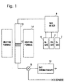
- Fig. 1 is a schematic block diagram showing a fixed bed reactor charged with a catalyst for producing carbon according to the present invention for measuring carbon producibility.
- a hydrogen gas cylinder 2, a carbon dioxide gas cylinder 4 and a nitrogen gas cylinder 6 are provided as gas supply sources and connected to a gas mixer 8 mixing carbon dioxide gas, hydrogen gas and nitrogen gas in prescribed ratios.
- the reaction tube 10 is charged with a catalyst 12 mainly composed of cobalt or nickel. Glass beads or glass wool charged in the reaction tube 10 fixes the catalyst 12.
- a heating furnace 14 heats the reaction tube 10 to a prescribed temperature.
- the gas passing through the reaction tube 10 is discharged or switched at any time by a switching valve 18 and fed to a gas chromatograph 16.
- the gas chromatograph 16 measures the concentrations of carbon monoxide, carbon dioxide, nitrogen and methane.
- Cobalt metal powder of 99.0 % in purity, nickel metal powder of 99.0 % in purity, nickel metallic particles of 90 % in purity and 16 to 62 ⁇ m in particle diameter and potassium nitrate of 99.0 % in purity were employed as reagents.
- the cobalt metal powder was used as a cobalt metal powder catalyst (a) as such.
- the nickel metal powder was used as a nickel metal powder catalyst (b) as such.
- the nickel metallic particles were used as a nickel metallic particle catalyst (c) as such.
- a proper quantity of potassium nitrate was put in a glass container and dissolved with addition of deionized water.
- Cobalt metal powder was added to the solution so that the weight ratio of potassium in potassium nitrate to the total weight of the catalyst was 1 %, and the mixture was stirred in an ultrasonic cleaner with ultrasonic waves for 15 minutes and thereafter dried on a hot plate for four hours. Thereafter, the dried catalyst was moved onto a porcelain dish and baked in an electric furnace under conditions of an air atmosphere, a baking temperature of 350°C and a baking time of four hours.
- a proper quantity of potassium nitrate was put in a glass container and dissolved with addition of deionized water.
- Nickel metal powder was added to the solution so that the weight ratio of potassium in potassium nitrate to the total weight of the catalyst was 1 %, and the mixture was stirred in an ultrasonic cleaner with ultrasonic waves for 15 minutes and thereafter dried on a hot plate for four hours. Thereafter the dried catalyst was moved onto a porcelain dish and baked in an electric furnace under conditions of an air atmosphere, a baking temperature of 350°C and a baking time of four hours.
- a proper quantity of potassium nitrate was put in a glass container and dissolved with addition of deionized water.
- Nickel metallic particles were added to the solution so that the weight ratio of potassium in potassium nitrate to the total weight of the catalyst was 1 %, and the mixture was stirred in an ultrasonic cleaner with ultrasonic waves for 15 minutes and thereafter dried on a hot plate for four hours. Thereafter the dried catalyst was moved onto a porcelain dish and baked in an electric furnace under conditions of an air atmosphere, a baking temperature of 500°C and a baking time of four hours.
- the cobalt metal powder catalyst (a) was charged by 0.1 g in the reaction tube 10 of the fixed bed reactor shown in Fig. 1 as the catalyst 12 and reduced under a hydrogen atmosphere at 400°C for 1 hour. Thereafter, the reaction tube 10 was heated with the heating furnace 14, while a mixed gas containing nitrogen gas, carbon dioxide gas and hydrogen gas was supplied, for measuring the carbon amount produced from weight change before and after the reaction.
- nitrogen gas, carbon dioxide gas and hydrogen gas were in the ratios 1:3:6, the flow rate of the mixed gas was 800 ml/min., the reaction temperature was 520°C and the reaction time (time with stable reaction conditions; this also applies to the following description) was 12 hours. Because nitrogen remains unchanged before and after the reaction, it was employed as an internal standard reference material for obtaining the sample collection quantity in the comparative examples and examples.
- the quantity of the produced carbon was 0.71 g
- the mean conversion ratio of carbon dioxide gas to carbon was 0.77 %
- the carbon deposition quantity was 528 g-carbon/kg-cat ⁇ h
- the weight ratio of the produced carbon to the catalyst (cobalt) was 7:1.
- the mixture of the cobalt metal powder catalyst (a) and carbon obtained in the aforementioned carbon production was charged by 0.4 g (0.05 g of cobalt and 0.35 g of carbon) in the reaction tube 10 of the fixed bed reactor shown in Fig. 1 as the catalyst 12, and the reaction tube 10 was heated with the heating furnace 14, while a mixed gas containing nitrogen gas, carbon dioxide gas and hydrogen gas was supplied, for measuring the carbon amount produced from weight change before and after the reaction.
- nitrogen gas, carbon dioxide gas and hydrogen gas were in the ratios 1:3:6, the flow rate of the mixed gas was 800 ml/min., the reaction temperature was 520°C and the reaction time was 13.3 hours.
- the quantity of the produced carbon was 0.29 g
- the mean conversion ratio of carbon dioxide gas to carbon was 0.28 %
- the carbon deposition quantity was 436 g-carbon/kg-cat ⁇ h
- the weight ratio of the produced carbon to the catalyst (cobalt) was 13:1.
- the cobalt metal powder catalyst (a) was charged by 1.00 g in the reaction tube 10 of the fixed bed reactor shown in Fig. 1 as the catalyst 12 and reduced under a hydrogen atmosphere at 400°C for 1 hour. Thereafter, the temperature of the reaction tube 10 was repetitively raised with the heating furnace 14 in the range of 250 to 620°C, while a mixed gas containing nitrogen gas, carbon dioxide gas and hydrogen gas was supplied, and the reacted gas was measured with the gas chromatograph 16 for determining the quantities of products. In this reaction, nitrogen gas, carbon dioxide gas and hydrogen gas were in the ratios 1:3:6, the flow rate of the mixed gas was 400 ml/min., and the programming rate was 2°C/min.
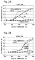
- Figs. 2A to 2E show conversion ratios of carbon dioxide to respective products obtained by repetitively raising the temperature five times in the second comparative example.
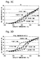
- Figs. 3A to 3C illustrate conversion ratios of carbon dioxide to carbon, methane and carbon monoxide obtained by repetitively raising the temperature five times
- Fig. 3D illustrates total conversion ratios in the second comparative example.
- the horizontal axis shows the catalyst temperatures (°C) and the vertical axis shows the carbon dioxide conversion ratios (%).
- the gas from the reaction tube 10 was analyzed at every temperature shown in Figs. 2A to 2E and 3A to 3D.
- the quantities of carbon monoxide, carbon dioxide, methane and nitrogen were measured with the gas chromatograph 16 and the total quantity of detected carbon monoxide, carbon dioxide and methane was subtracted from the quantity of supplied carbon dioxide for obtaining the carbon content.
- the total conversion ratios were obtained by subtracting the quantities of detected carbon dioxide from the quantity of supplied carbon dioxide.
- the maximum conversion ratio of carbon dioxide gas to carbon was 6.8 % with a peak of 510 to 520°C.
- the conversion ratio to carbon which was increased up to the fourth temperature rise, was liable to decrease in the fifth temperature rise.
- the cobalt metal powder catalyst (a) was charged by 0.1006 g in the reaction tube 10 of the fixed bed reactor shown in Fig. 1 as the catalyst 12, reduced under a hydrogen atmosphere at 400°C for 1 hour. Thereafter, the reaction tube 10 was heated with the heating furnace 14, while a mixed gas containing nitrogen gas, carbon dioxide gas and hydrogen gas was supplied, for measuring the carbon amount produced from weight change before and after the reaction.
- nitrogen gas, carbon dioxide gas and hydrogen gas were in the ratios 1:3:6, the flow rate of the mixed gas was 100 ml/min., the reaction temperature was 520°C, and the reaction time was 7.3 hours.
- Fig. 4 shows the reaction times and conversion ratios of carbon dioxide to respective products in the third comparative example.
- the horizontal axis shows the times (hour) and the vertical axis shows the carbon dioxide conversion ratios (%).
- the gas from the reaction tube 10 was analyzed at every time shown in Fig. 4, and the conversion ratios to carbon monoxide, methane and carbon, and the total conversion ratio were obtained similarly to the second comparative example.
- the quantity of the produced carbon was 0.2945 g
- the mean conversion ratio of carbon dioxide gas to carbon was 4.2 %
- the carbon deposition quantity was 401 g-carbon/kg-cat ⁇ h.
- the cobalt metal powder catalyst (a) was charged by 0.3 to 5 g in the reaction tube 10 of the fixed bed reactor shown in Fig. 1 as the catalyst 12 and reduced under a hydrogen atmosphere at 400°C for 1 hour. Thereafter, the reaction tube 10 was heated to 510°C with the heating furnace 14, while a mixed gas containing nitrogen gas, carbon dioxide gas and hydrogen gas was supplied at a flow rate of 200 to 400 ml/min., for measuring the carbon amount produced from weight change before and after the reaction. In this reaction, nitrogen gas, carbon dioxide gas and hydrogen gas were in the ratios 1:3:6, and the reaction time was 7 to 13 hours.
- Fig. 5 shows the carbon deposition quantity and the mean conversion ratio in the case of changing the space velocity (SV: mixed gas flow rate per unit catalytic weight ⁇ unit time) in the fourth comparative example.
- the vertical axis shows the carbon deposition quantity (g-carbon/kg-cat ⁇ h) or the mean conversion ratio (%) and the horizontal axis shows the space velocity SV (ml/g-cat ⁇ h).
- the nickel metal powder catalyst (b) was charged by 0.1003 g in the reaction tube 10 of the fixed bed reactor shown in Fig. 1 as the catalyst 12, reduced under a hydrogen atmosphere at 400°C for 1 hour. Thereafter, the reaction tube 10 was heated with the heating furnace 14, while a mixed gas containing nitrogen gas, carbon dioxide gas and hydrogen gas was supplied, for measuring the carbon amount produced from weight change before and after the reaction.
- nitrogen gas, carbon dioxide gas and hydrogen gas were in the ratios 1:3:6, the flow rate of the mixed gas was 100 ml/min., the reaction temperature was 520°C, and the reaction time was 10 hours.
- Fig. 6 shows the reaction times and the mean conversion ratios to respective products in the fifth comparative example.
- the horizontal axis shows the times (hour) and the vertical axis shows the carbon dioxide conversion ratios (%).
- the gas from the reaction tube 10 was analyzed at every time shown in Fig. 6, and the conversion ratios to carbon monoxide, methane and carbon, and the total conversion ratio were obtained similarly to the second comparative example.
- the nickel metallic particle catalyst (c) was charged by 0.1001 g in the reaction tube 10 of the fixed bed reactor shown in Fig. 1 as the catalyst 12, reduced under a hydrogen atmosphere at 400°C for 1 hour. Thereafter, the reaction tube 10 was heated with the heating furnace 14, while a mixed gas containing nitrogen gas, carbon dioxide gas and hydrogen gas was supplied, for measuring the carbon amount produced from weight change before and after the reaction.
- nitrogen gas, carbon dioxide gas and hydrogen gas were in the ratios 1:3:6, the flow rate of the mixed gas was 100 ml/min., the reaction temperature was 500°C, and the reaction time was 10 hours.
- Fig. 7 shows the reaction times and the mean conversion ratios to respective products in the sixth comparative example.
- the horizontal axis shows the times (hour) and the vertical axis shows the carbon dioxide conversion ratios (%).
- the gas from the reaction tube 10 was analyzed at every time shown in Fig. 7, and the conversion ratios to carbon monoxide, methane and carbon, and the total conversion ratio were obtained similarly to the second comparative example.
- the 1 % potassium-added cobalt catalyst (A) was charged by 0.32 g in the reaction tube 10 of the fixed bed reactor shown in Fig. 1 as the catalyst 12 and reduced under a hydrogen atmosphere at 400°C for 1 hour. After the reduction, the weight of the catalyst 12 was 0.25 g. This weight of the reduced catalyst 12 was calculated on the basis of a weight decrease ratio after reduction obtained in another reactor. This also applies to the remaining Examples. Thereafter, the temperature of the reaction tube 10 was repetitively raised with the heating furnace 14 in the range of 250 to 620°C, while a mixed gas containing nitrogen gas, carbon dioxide gas and hydrogen gas was supplied, and the reacted gas was measured with the gas chromatograph 16 for determining the quantities of products. In this reaction, nitrogen gas, carbon dioxide gas and hydrogen gas were in the ratios 1:3:6, the flow rate of the mixed gas was 100 ml/min., and the programming rate was 2°C/min.
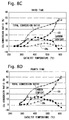
- Figs. 8A to 8E show conversion ratios of carbon dioxide to respective products obtained by repetitively raising the temperature five times in the first Example.
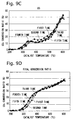
- Figs. 9A to 9C illustrate conversion ratios of carbon dioxide to carbon, methane and carbon monoxide obtained by repetitively raising the temperature five times
- Fig. 9D illustrates total conversion ratio in the first Example.
- the horizontal axis shows the catalyst temperatures (°C)
- the vertical axis shows the carbon dioxide conversion ratios (%).
- the gas from the reaction tube 10 was analyzed at every temperature shown in Figs. 8A to 8E and 9A to 9D.
- the conversion ratios of carbon dioxide to carbon monoxide, methane and carbon, and the total conversion ratio were obtained similarly to the second comparative example.
- the maximum conversion ratio of carbon dioxide gas to carbon was 180 % with a peak of 410 to 430°C.
- the 1 % potassium-added nickel catalyst (B) was charged by 0.26 g in the reaction tube 10 of the fixed bed reactor shown in Fig. 1 as the catalyst 12 and reduced under a hydrogen atmosphere at 400°C for 1 hour. After the reduction, the weight of the catalyst 12 was 0.25 g. Thereafter, the temperature of the reaction tube 10 was repetitively raised with the heating furnace 14 in the range of 250 to 620°C, while a mixed gas containing nitrogen gas, carbon dioxide gas and hydrogen gas was supplied, and the reacted gas was measured with the gas chromatograph 16 for determining the quantities of products. In this reaction, nitrogen gas, carbon dioxide gas and hydrogen gas were in the ratios 1:3:6, the flow rate of the mixed gas was 100 ml/min., and the programming rate was 2°C/min.
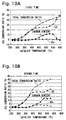
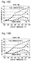
- Figs. 10A to 10E show conversion ratios of carbon dioxide to respective products obtained by repetitively raising the temperature five times in the second Example.
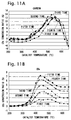
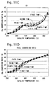
- Figs. 11A to 11C illustrate conversion ratios of carbon dioxide to carbon, methane and carbon monoxide obtained by repetitively raising the temperature five times
- Fig. 11D illustrates total conversion ratio, in the second Example.
- the horizontal axis shows the catalyst temperatures (°C) and the vertical axis shows the carbon dioxide conversion ratios (%).
- the gas from the reaction tube 10 was analyzed at every temperature shown in Figs. 10A to 10E and 11A to 11D, and the conversion ratios of carbon dioxide to carbon monoxide, methane and carbon, and the total conversion ratios were obtained similarly to the second comparative example.
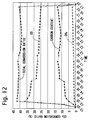
- the 1 % potassium-added cobalt catalyst (A) was charged by 0.64 g in the reaction tube 10 of the fixed bed reactor shown in Fig. 1 as the catalyst 12 and reduced under a hydrogen atmosphere at 400°C for 1 hour. After the reduction, the weight of the catalyst 12 was 0.50 g. Thereafter, the temperature of the reaction tube 10 was raised with the heating furnace 14, while a mixed gas containing nitrogen gas, carbon dioxide gas and hydrogen gas was supplied, for measuring the carbon amount produced from weight change before and after the reaction. In this reaction, nitrogen gas, carbon dioxide gas and hydrogen gas were in the ratios 1:3:6, the flow rate of the mixed gas was 100 ml/min., the reaction temperature was 520°C, and the reaction time was 10 hours.
- Fig. 12 shows the reaction times and the conversion ratios of carbon dioxide to respective products in the third Example.
- the horizontal axis shows the times and the vertical axis shows the carbon dioxide conversion ratios (%).
- the gas from the reaction tube 10 was analyzed at every temperature shown in Fig. 12, and the conversion ratios to carbon monoxide, methane and carbon, and the total conversion ratios were obtained similarly to second comparative example.
- the quantity of the produced carbon was 1.56 g
- the mean conversion ratio of carbon dioxide gas to carbon was 16.2 %
- the carbon deposition quantity was 312 g-carbon/kg-cat ⁇ h.
- the 1 % potassium-added cobalt catalyst (A) was charged by 0.64 g in the reaction tube 10 of the fixed bed reactor shown in Fig. 1 as the catalyst 12 and reduced under a hydrogen atmosphere at 400°C for 1 hour. After the reduction, the weight of the catalyst 12 was 0.50 g. Thereafter, the temperature of the reaction tube 10 was raised with the heating furnace 14, while a mixed gas containing nitrogen gas, carbon dioxide gas and hydrogen gas was supplied, for measuring the carbon amount produced from weight change before and after the reaction. In this reaction, nitrogen gas, carbon dioxide gas and hydrogen gas were in the ratios 1:3:6, the flow rate of the mixed gas was 800 ml/min., the reaction temperature was 520°C, and the reaction time was 40 minutes.
- Fig. 13 shows the reaction times and the conversion ratios of carbon dioxide to respective products in the fourth Example.
- the horizontal axis shows the times (hour) and the vertical axis shows the carbon dioxide conversion ratios (%).
- the gas from the reaction tube 10 was analyzed at every temperature shown in Fig. 13, and the conversion ratios to carbon monoxide, methane and carbon, and the total conversion ratios were obtained similarly to the second comparative example.
- the quantity of the produced carbon was 0.71 g
- the mean conversion ratio of carbon dioxide gas to carbon was 13.8 %
- the carbon deposition quantity was 1065 g-carbon/kg-cat ⁇ h.
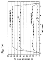
- the 1 % potassium-added cobalt catalyst (A) was charged by 0.38 g in the reaction tube 10 of the fixed bed reactor shown in Fig. 1 as the catalyst 12 and reduced under a hydrogen atmosphere at 400°C for 1 hour. After the reduction, the weight of the catalyst 12 was 0.30 g. Thereafter, the temperature of the reaction tube 10 was raised with the heating furnace 14, while a mixed gas containing nitrogen gas, carbon dioxide gas and hydrogen gas was supplied, for measuring the carbon amount produced from weight change before and after the reaction. In this reaction, nitrogen gas, carbon dioxide gas and hydrogen gas were in the ratios 1:3:6, the flow rate of the mixed gas was 400 ml/min., the reaction temperature was 520°C, and the reaction time was 4.5 hours.
- Fig. 14 shows the reaction times and the conversion ratios of carbon dioxide to respective products in the fifth Example.
- the horizontal axis shows the times (hour) and the vertical axis shows the carbon dioxide conversion ratios (%).
- the gas from the reaction tube 10 was analyzed at every temperature shown in Fig. 14, and the conversion ratios to carbon monoxide, methane and carbon, and the total conversion ratios were obtained similarly to second comparative example.
- the quantity of the produced carbon was 1.75 g
- the mean conversion ratio of carbon dioxide gas to carbon was 10.5 %
- the carbon deposition quantity was 1356 g-carbon/kg-cat ⁇ h.
- the 1 % potassium-added cobalt catalyst (A) was charged by 0.0158 g in the reaction tube 10 of the fixed bed reactor shown in Fig. 1 as the catalyst 12 and reduced under a hydrogen atmosphere at 400°C for 1 hour. After the reduction, the weight of the catalyst 12 was 0.0123 g. Thereafter, the temperature of the reaction tube 10 was raised with the heating furnace 14, while a mixed gas containing nitrogen gas, carbon dioxide gas and hydrogen gas was supplied, for measuring the carbon amount produced from weight change before and after the reaction. In this reaction, nitrogen gas, carbon dioxide gas and hydrogen gas were in the ratios 1:4:8, the flow rate of the mixed gas was 65 ml/min., the reaction temperature was 520°C, and the reaction time was 5 hours.
- Fig. 15 shows the reaction times and the conversion ratios of carbon dioxide to respective products in the sixth Example.
- the horizontal axis shows the times (hour) and the vertical axis shows the carbon dioxide conversion ratios (%).
- the gas from the reaction tube 10 was analyzed at every temperature shown in Fig. 15, and the conversion ratios to carbon monoxide, methane and carbon, and the total conversion ratios were obtained similarly to second comparative example.
- the quantity of the produced carbon was 0.1647 g
- the mean conversion ratio of carbon dioxide gas to carbon was 5.1 %
- the carbon deposition quantity was 2678 g-carbon/kg-cat ⁇ h.
- the 1 % potassium-added cobalt catalyst (A) was charged by 0.1270 g in the reaction tube 10 of the fixed bed reactor shown in Fig. 1 as the catalyst 12 and reduced under a hydrogen atmosphere at 400°C for 1 hour. After the reduction, the weight of the catalyst 12 was 0.0992 g. Thereafter, the temperature of the reaction tube 10 was raised with the heating furnace 14, while a mixed gas containing nitrogen gas, carbon dioxide gas and hydrogen gas was supplied, for measuring the carbon amount produced from weight change before and after the reaction. In this reaction, nitrogen gas, carbon dioxide gas and hydrogen gas were in the ratios 1:3:6, the flow rate of the mixed gas was 100 ml/min., the reaction temperature was 410°C, and the reaction time was 1 hour 13 minutes.
- the quantity of the produced carbon was 0.2098 g
- the mean conversion ratio of carbon dioxide gas to carbon was 17.9 %
- the carbon deposition quantity was 1738 g-carbon/kg-cat ⁇ h.
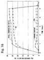
- the 1 % potassium-added cobalt catalyst (A) was charged by 0.0112 g in the reaction tube 10 of the fixed bed reactor shown in Fig. 1 as the catalyst 12 and reduced under a hydrogen atmosphere at 400°C for 1 hour. After the reduction, the weight of the catalyst 12 was 0.0087 g. Thereafter, the temperature of the reaction tube 10 was raised with the heating furnace 14, while a mixed gas containing nitrogen gas, carbon dioxide gas and hydrogen gas was supplied, for measuring the carbon amount produced from weight change before and after the reaction. In this reaction, nitrogen gas, carbon dioxide gas and hydrogen gas were in the ratios 1:3:6, the flow rate of the mixed gas was 100 ml/min., the reaction temperature was 410°C, and the reaction time was 5 hours.
- Fig. 16 shows the reaction times and the conversion ratios of carbon dioxide to respective products in the eighth Example.
- the horizontal axis shows the times (hour) and the vertical axis shows the carbon dioxide conversion ratios (%).
- the gas from the reaction tube 10 was analyzed every temperature shown in Fig. 16, and the conversion ratios to carbon monoxide, methane and carbon, and the total conversion ratios were obtained similarly to the second comparative example.
- the quantity of the produced carbon was 0.0816 g
- the mean conversion ratio of carbon dioxide gas to carbon was 1.7 %
- the carbon deposition quantity was 1876 g-carbon/kg-cat ⁇ h.
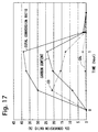
- the 1 % potassium-added cobalt catalyst (A) was charged by 0.1268 g in the reaction tube 10 of the fixed bed reactor shown in Fig. 1 as the catalyst 12 and reduced under a hydrogen atmosphere at 400°C for 1 hour. After the reduction, the weight of the catalyst 12 was 0.0990 g. Thereafter, the temperature of the reaction tube 10 was raised with the heating furnace 14, while a mixed gas containing nitrogen gas, carbon dioxide gas and hydrogen gas was supplied, for measuring the carbon amount produced from weight change before and after the reaction. In this reaction, nitrogen gas, carbon dioxide gas and hydrogen gas were in the ratios 1:3:6, the flow rate of the mixed gas was 100 ml/min., the reaction temperature was 410°C, and the reaction time was 1 hour.
- Fig. 17 shows the reaction times and the conversion ratios of carbon dioxide to respective products in the ninth Example.
- the horizontal axis shows the times (hour) and the vertical axis shows the carbon dioxide conversion ratios (%).
- the gas from the reaction tube 10 was analyzed at every temperature shown in Fig. 17, and the conversion ratios to carbon monoxide, methane and carbon, and the total conversion ratios were obtained similarly to the second comparative example.
- the quantity of the produced carbon was 0.1619 g
- the mean conversion ratio of carbon dioxide gas to carbon was 16.8 %
- the carbon deposition quantity was 1635 g-carbon/kg-cat ⁇ h.
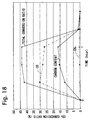
- the 1 % potassium-added cobalt catalyst (A) was charged by 0.1267 g in the reaction tube 10 of the fixed bed reactor shown in Fig. 1 as the catalyst 12 and reduced under a hydrogen atmosphere at 400°C for 1 hour. After the reduction, the weight of the catalyst 12 was 0.0989 g. Thereafter, the temperature of the reaction tube 10 was raised with the heating furnace 14, while a mixed gas containing nitrogen gas, carbon dioxide gas and hydrogen gas was supplied, for measuring the carbon amount produced from weight change before and after the reaction. In this reaction, nitrogen gas, carbon dioxide gas and hydrogen gas were in the ratios 1:3:6, the flow rate of the mixed gas was 100 ml/min., the reaction temperature was 500°C, and the reaction time was 1 hour.
- Fig. 18 shows the reaction times and the conversion ratios of carbon dioxide to respective products in the tenth Example.
- the horizontal axis shows the times (hour) and the vertical axis shows the carbon dioxide conversion ratios (%).
- the gas from the reaction tube 10 was analyzed at every temperature shown in Fig. 18, and the conversion ratios to carbon monoxide, methane and carbon, and the total conversion ratios were obtained similarly to the second comparative example.
- the quantity of the produced carbon was 0.1357 g
- the mean conversion ratio of carbon dioxide gas to carbon was 14.1 %
- the carbon deposition quantity was 1372 g-carbon/kg-cat ⁇ h.
- the 1 % potassium-added nickel catalyst (B) was charged by 0.1039 g in the reaction tube 10 of the fixed bed reactor shown in Fig. 1 as the catalyst 12 and reduced under a hydrogen atmosphere at 400°C for 1 hour. After the reduction, the weight of the catalyst 12 was 0.1015 g. Thereafter, the temperature of the reaction tube 10 was raised with the heating furnace 14, while a mixed gas containing nitrogen gas, carbon dioxide gas and hydrogen gas was supplied, for measuring the carbon amount produced from weight change before and after the reaction. In this reaction, nitrogen gas, carbon dioxide gas and hydrogen gas were in the ratios 1:3:6, the flow rate of the mixed gas was 100 ml/min., the reaction temperature was 500°C, and the reaction time was 1.75 hours.
- Fig. 19 shows the reaction times and the conversion ratios of carbon dioxide to respective products in the eleventh Example.
- the horizontal axis shows the times (hour) and the vertical axis shows the carbon dioxide conversion ratios (%).
- the gas from the reaction tube 10 was analyzed at every temperature shown in Fig. 19, and the conversion ratios to carbon monoxide, methane and carbon, and the total conversion ratios were obtained similarly to second comparative example.
- the quantity of the produced carbon was 0.1517 g
- the mean conversion ratio of carbon dioxide gas to carbon was 9.0 %
- the carbon deposition quantity was 854 g-carbon/kg-cat ⁇ h.
- the 1 % potassium-added nickel particle catalyst (C) was charged by 0.1043 g in the reaction tube 10 of the fixed bed reactor shown in Fig. 1 as the catalyst 12 and reduced under a hydrogen atmosphere at 400°C for 1 hour. After the reduction, the weight of the catalyst 12 was 0.1022 g. Thereafter, the temperature of the reaction tube 10 was raised with the heating furnace 14, while a mixed gas containing nitrogen gas, carbon dioxide gas and hydrogen gas was supplied, for measuring the carbon amount produced from weight change before and after the reaction. In this reaction, nitrogen gas, carbon dioxide gas and hydrogen gas were in the ratios 1:3:6, the flow rate of the mixed gas was 100 ml/min., the reaction temperature was 500°C, and the reaction time was 3.25 hours.
- Fig. 20 shows the reaction times and the conversion ratios of carbon dioxide to respective products in the twelfth Example.
- the horizontal axis shows the times (hour) and the vertical axis shows the carbon dioxide conversion ratios (%).
- the gas from the reaction tube 10 was analyzed at every temperature shown in Fig. 20, and the conversion ratios to carbon monoxide, methane and carbon, and the total conversion ratios were obtained similarly to the second comparative example.
- the quantity of the produced carbon was 0.1499 g
- the mean conversion ratio of carbon dioxide gas to carbon was 4.8 %
- the carbon deposition quantity was 451 g-carbon/kg-cat ⁇ h.
- the optimum catalyst temperature in the second comparative example was 510 to 520°C while it was possible to lower the optimum catalyst temperature to 410 to 430°C in first Example, and the maximum conversion ratio in the second comparative example was 6.8 % while it was possible to improve the maximum conversion ratio to 18.0 % in the first Example.
- the inventive catalyst for producing carbon which can produce carbon at lower energy as compared with the conventional method of producing carbon by reducing carbon dioxide, can efficiently contribute to curtailment of discharge of carbon dioxide.
Landscapes
- Chemical & Material Sciences (AREA)
- Organic Chemistry (AREA)
- Engineering & Computer Science (AREA)
- Materials Engineering (AREA)
- Chemical Kinetics & Catalysis (AREA)
- Inorganic Chemistry (AREA)
- Catalysts (AREA)
- Organic Low-Molecular-Weight Compounds And Preparation Thereof (AREA)
- Carbon And Carbon Compounds (AREA)
Abstract
Description
Claims (10)
- A catalyst for producing carbon employed for producing carbon by coming into contact with mixed gas containing a carbon source,mainly composed of at least either nickel or cobalt with an alkaline metallic element added thereto.
- The catalyst according to claim 1,mainly composed of cobalt with potassium added thereto as said alkaline metallic element.
- The catalyst according to claim 1,mainly composed of nickel with potassium added thereto as said alkaline metallic component.
- A method of producing carbon by bringing a catalyst mainly composed of at least either nickel or cobalt with an alkaline metallic element added thereto into contact with mixed gas containing a carbon source.
- The method of producing carbon according to claim 4, whereinsaid catalyst is mainly composed of cobalt with potassium added thereto as said alkaline metallic component, said method making reaction under a condition of a reaction temperature of 350 to 550°C.
- The method of producing carbon according to claim 5, making said reaction under a condition of a reaction temperature of 410 to 430°C.
- The method of producing carbon according to claim 4, whereinsaid catalyst is mainly composed of nickel with potassium added thereto as said alkaline metallic component, said method making reaction under a condition of a reaction temperature of 400 to 610°C.
- The method of producing carbon according to claim 7, making said reaction under a condition of a reaction temperature of 480 to 600°C.
- The method of producing carbon according to claim 4, wherein said mixed gas contains carbon dioxide as said carbon source.
- The method of producing carbon according to claim 9, wherein said mixed gas further contains hydrogen.
Applications Claiming Priority (2)
| Application Number | Priority Date | Filing Date | Title |
|---|---|---|---|
| JP14308199A JP4211882B2 (en) | 1999-05-24 | 1999-05-24 | Catalyst for carbon production |
| JP14308199 | 1999-05-24 |
Publications (2)
| Publication Number | Publication Date |
|---|---|
| EP1055454A2 true EP1055454A2 (en) | 2000-11-29 |
| EP1055454A3 EP1055454A3 (en) | 2002-02-13 |
Family
ID=15330481
Family Applications (1)
| Application Number | Title | Priority Date | Filing Date |
|---|---|---|---|
| EP00109981A Withdrawn EP1055454A3 (en) | 1999-05-24 | 2000-05-11 | Catalyst for producing carbon and method of producing carbon |
Country Status (6)
| Country | Link |
|---|---|
| US (1) | US6582674B1 (en) |
| EP (1) | EP1055454A3 (en) |
| JP (1) | JP4211882B2 (en) |
| KR (1) | KR100413635B1 (en) |
| CN (1) | CN1189389C (en) |
| RU (1) | RU2177365C1 (en) |
Families Citing this family (3)
| Publication number | Priority date | Publication date | Assignee | Title |
|---|---|---|---|---|
| US20050112050A1 (en) * | 2003-11-21 | 2005-05-26 | Pradhan Bhabendra K. | Process to reduce the pre-reduction step for catalysts for nanocarbon synthesis |
| KR101533580B1 (en) * | 2015-03-12 | 2015-07-03 | 그린루브 주식회사 | Water-soluble cutting lubricant additive useful in Ricinolic Acid |
| JP2021069963A (en) * | 2019-10-29 | 2021-05-06 | 日本製鉄株式会社 | Carbon dioxide decomposition apparatus |
Family Cites Families (6)
| Publication number | Priority date | Publication date | Assignee | Title |
|---|---|---|---|---|
| US3842113A (en) | 1970-11-25 | 1974-10-15 | Sagami Chem Res | Catalyst for reducing carbon dioxide |
| NL7304543A (en) * | 1972-04-15 | 1973-10-17 | ||
| US4452676A (en) * | 1982-04-30 | 1984-06-05 | United Technologies Corporation | Carbon dioxide conversion system for oxygen recovery |
| JPH01282313A (en) * | 1988-05-10 | 1989-11-14 | Asahi Chem Ind Co Ltd | Production of carbon fiber |
| IT1244427B (en) * | 1990-07-05 | 1994-07-15 | Eduardo Luigi Szego | HYDROCARBON COMBUSTION PROCESS IN WHICH THE DISPERSION OF THE CARBON DIOXIDE PRODUCED INTO THE ATMOSPHERE IS AVOIDED AND THE PLANT IS REALIZED |
| JP3415038B2 (en) * | 1998-03-25 | 2003-06-09 | 株式会社島津製作所 | Carbon production method |
-
1999
- 1999-05-24 JP JP14308199A patent/JP4211882B2/en not_active Expired - Fee Related
-
2000
- 2000-04-24 CN CNB001059734A patent/CN1189389C/en not_active Expired - Fee Related
- 2000-04-26 KR KR10-2000-0022099A patent/KR100413635B1/en not_active Expired - Fee Related
- 2000-05-01 US US09/562,738 patent/US6582674B1/en not_active Expired - Fee Related
- 2000-05-11 EP EP00109981A patent/EP1055454A3/en not_active Withdrawn
- 2000-05-23 RU RU2000112847/12A patent/RU2177365C1/en active
Also Published As
| Publication number | Publication date |
|---|---|
| KR100413635B1 (en) | 2003-12-31 |
| JP2000325794A (en) | 2000-11-28 |
| KR20010049293A (en) | 2001-06-15 |
| CN1274680A (en) | 2000-11-29 |
| JP4211882B2 (en) | 2009-01-21 |
| EP1055454A3 (en) | 2002-02-13 |
| CN1189389C (en) | 2005-02-16 |
| RU2177365C1 (en) | 2001-12-27 |
| US6582674B1 (en) | 2003-06-24 |
Similar Documents
| Publication | Publication Date | Title |
|---|---|---|
| Johnson et al. | Orientation of complex molecules chemisorbed on metal surfaces: near-edge X-ray absorption | |
| KR930003749B1 (en) | Production of heavy metal carbides with high specific surface area | |
| CN104056627B (en) | A kind of preparation of low carbon olefines by synthetic gas catalyst and the application in fischer-tropsch reaction thereof | |
| CN117884159B (en) | A catalytic material for water-gas shift reaction, its preparation method and application | |
| JP2014506183A (en) | Method for producing methane synthesis catalyst and catalyst precursor | |
| CN111167460A (en) | Preparation of H by direct cracking of natural gas2Catalyst with CNTs (carbon nanotubes), and preparation method and application thereof | |
| CN113117712A (en) | Methane dry reforming reaction under microwave condition and catalyst thereof | |
| US6582674B1 (en) | Catalyst for producing carbon and method of producing carbon | |
| CN103157486A (en) | Preparation method for oxide catalyst, and oxide catalyst prepared by same | |
| CN114308093A (en) | High-loaded nickel-based carbide catalyst, preparation method and application thereof | |
| WO1999043608A1 (en) | Hydrogen production via the direct cracking of hydrocarbons | |
| JP2545734B2 (en) | Hydrocarbon producing catalyst and hydrocarbon producing method | |
| CN114733562B (en) | High-activity methane-methanol oxygen-free co-aromatization catalyst and preparation method and application thereof | |
| JP7514485B2 (en) | Carbon Dioxide Reduction Catalyst | |
| KR20150087557A (en) | Metal-doped titanium oxide nanowire catalyst, preparing method of the same and method for oxidative coupling reaction of methane using the same | |
| CN113941360A (en) | Catalyst for oxygen-free aromatization of methane and preparation method and application thereof | |
| CN1131170C (en) | Process for producing synthetic gas by microwave rein forced mathane and CO2 reformation | |
| CN117185274A (en) | A non-metallic phosphorus-doped lanthanum iron-based perovskite oxygen carrier, preparation method and application | |
| Yan et al. | The formation of a lithium–iridium complex hydride toward ammonia synthesis | |
| CN114471516B (en) | Solid base catalyst for synthesizing methyl acrylate and preparation method thereof | |
| CN102407119A (en) | A kind of cordierite substrate catalyst for methane carbon dioxide reforming to produce synthesis gas and preparation method thereof | |
| Qin et al. | Ni/MgO catalyst prepared using atmospheric high-frequency discharge plasma for CO2 reforming of methane | |
| CN111111726A (en) | Preparation method and application of a catalyst for oxidative dehydrogenation of propane to prepare propylene | |
| CN116850989B (en) | Solid core-shell catalyst and its preparation method and application | |
| CN1281312C (en) | Nickel series conversion catalyst using alpha-Al2-O3 as carrier |
Legal Events
| Date | Code | Title | Description |
|---|---|---|---|
| PUAI | Public reference made under article 153(3) epc to a published international application that has entered the european phase |
Free format text: ORIGINAL CODE: 0009012 |
|
| AK | Designated contracting states |
Kind code of ref document: A2 Designated state(s): AT BE CH CY DE DK ES FI FR GB GR IE IT LI LU MC NL PT SE Kind code of ref document: A2 Designated state(s): DE FR GB |
|
| AX | Request for extension of the european patent |
Free format text: AL;LT;LV;MK;RO;SI |
|
| PUAL | Search report despatched |
Free format text: ORIGINAL CODE: 0009013 |
|
| AK | Designated contracting states |
Kind code of ref document: A3 Designated state(s): AT BE CH CY DE DK ES FI FR GB GR IE IT LI LU MC NL PT SE |
|
| AX | Request for extension of the european patent |
Free format text: AL;LT;LV;MK;RO;SI |
|
| 17P | Request for examination filed |
Effective date: 20020403 |
|
| AKX | Designation fees paid |
Free format text: DE FR GB |
|
| 17Q | First examination report despatched |
Effective date: 20041228 |
|
| RTI1 | Title (correction) |
Free format text: METHOD FOR REDUCING SULPHUR AND CARBON IN PETROLEUM REFINING PROCESSES |
|
| 17Q | First examination report despatched |
Effective date: 20041228 |
|
| STAA | Information on the status of an ep patent application or granted ep patent |
Free format text: STATUS: THE APPLICATION IS DEEMED TO BE WITHDRAWN |
|
| 18D | Application deemed to be withdrawn |
Effective date: 20091201 |