EP1054490A2 - Line narrowed laser with spatial filter - Google Patents
Line narrowed laser with spatial filter Download PDFInfo
- Publication number
- EP1054490A2 EP1054490A2 EP00109628A EP00109628A EP1054490A2 EP 1054490 A2 EP1054490 A2 EP 1054490A2 EP 00109628 A EP00109628 A EP 00109628A EP 00109628 A EP00109628 A EP 00109628A EP 1054490 A2 EP1054490 A2 EP 1054490A2
- Authority
- EP
- European Patent Office
- Prior art keywords
- laser
- spatial filter
- line
- bandwidth
- aperture
- Prior art date
- Legal status (The legal status is an assumption and is not a legal conclusion. Google has not performed a legal analysis and makes no representation as to the accuracy of the status listed.)
- Granted
Links
- 230000001419 dependent effect Effects 0.000 claims abstract description 4
- 239000007789 gas Substances 0.000 claims description 9
- 230000003287 optical effect Effects 0.000 claims description 4
- 229910052731 fluorine Inorganic materials 0.000 claims description 3
- 239000011737 fluorine Substances 0.000 claims description 3
- 229910052734 helium Inorganic materials 0.000 claims description 2
- 239000001307 helium Substances 0.000 claims description 2
- SWQJXJOGLNCZEY-UHFFFAOYSA-N helium atom Chemical compound [He] SWQJXJOGLNCZEY-UHFFFAOYSA-N 0.000 claims description 2
- 239000000463 material Substances 0.000 claims description 2
- 229910052754 neon Inorganic materials 0.000 claims description 2
- GKAOGPIIYCISHV-UHFFFAOYSA-N neon atom Chemical compound [Ne] GKAOGPIIYCISHV-UHFFFAOYSA-N 0.000 claims description 2
- 239000006185 dispersion Substances 0.000 claims 4
- PXGOKWXKJXAPGV-UHFFFAOYSA-N Fluorine Chemical compound FF PXGOKWXKJXAPGV-UHFFFAOYSA-N 0.000 claims 1
- 238000000034 method Methods 0.000 abstract description 13
- 238000001914 filtration Methods 0.000 abstract description 9
- 230000009467 reduction Effects 0.000 abstract description 8
- 238000001228 spectrum Methods 0.000 description 11
- 230000003595 spectral effect Effects 0.000 description 8
- 238000002474 experimental method Methods 0.000 description 4
- BJQHLKABXJIVAM-UHFFFAOYSA-N bis(2-ethylhexyl) phthalate Chemical compound CCCCC(CC)COC(=O)C1=CC=CC=C1C(=O)OCC(CC)CCCC BJQHLKABXJIVAM-UHFFFAOYSA-N 0.000 description 3
- YCKRFDGAMUMZLT-UHFFFAOYSA-N Fluorine atom Chemical compound [F] YCKRFDGAMUMZLT-UHFFFAOYSA-N 0.000 description 2
- 238000005259 measurement Methods 0.000 description 2
- 239000002184 metal Substances 0.000 description 2
- 230000001902 propagating effect Effects 0.000 description 2
- 238000002310 reflectometry Methods 0.000 description 2
- 239000012780 transparent material Substances 0.000 description 2
- 241000030366 Scorpidinae Species 0.000 description 1
- VYPSYNLAJGMNEJ-UHFFFAOYSA-N Silicium dioxide Chemical compound O=[Si]=O VYPSYNLAJGMNEJ-UHFFFAOYSA-N 0.000 description 1
- 230000002411 adverse Effects 0.000 description 1
- 239000005350 fused silica glass Substances 0.000 description 1
- 238000010438 heat treatment Methods 0.000 description 1
- 238000000608 laser ablation Methods 0.000 description 1
- 238000001459 lithography Methods 0.000 description 1
- 238000004519 manufacturing process Methods 0.000 description 1
- 239000000203 mixture Substances 0.000 description 1
- 238000009304 pastoral farming Methods 0.000 description 1
Images



Classifications
-
- G—PHYSICS
- G03—PHOTOGRAPHY; CINEMATOGRAPHY; ANALOGOUS TECHNIQUES USING WAVES OTHER THAN OPTICAL WAVES; ELECTROGRAPHY; HOLOGRAPHY
- G03F—PHOTOMECHANICAL PRODUCTION OF TEXTURED OR PATTERNED SURFACES, e.g. FOR PRINTING, FOR PROCESSING OF SEMICONDUCTOR DEVICES; MATERIALS THEREFOR; ORIGINALS THEREFOR; APPARATUS SPECIALLY ADAPTED THEREFOR
- G03F7/00—Photomechanical, e.g. photolithographic, production of textured or patterned surfaces, e.g. printing surfaces; Materials therefor, e.g. comprising photoresists; Apparatus specially adapted therefor
- G03F7/70—Microphotolithographic exposure; Apparatus therefor
- G03F7/70008—Production of exposure light, i.e. light sources
- G03F7/70025—Production of exposure light, i.e. light sources by lasers
-
- G—PHYSICS
- G03—PHOTOGRAPHY; CINEMATOGRAPHY; ANALOGOUS TECHNIQUES USING WAVES OTHER THAN OPTICAL WAVES; ELECTROGRAPHY; HOLOGRAPHY
- G03F—PHOTOMECHANICAL PRODUCTION OF TEXTURED OR PATTERNED SURFACES, e.g. FOR PRINTING, FOR PROCESSING OF SEMICONDUCTOR DEVICES; MATERIALS THEREFOR; ORIGINALS THEREFOR; APPARATUS SPECIALLY ADAPTED THEREFOR
- G03F7/00—Photomechanical, e.g. photolithographic, production of textured or patterned surfaces, e.g. printing surfaces; Materials therefor, e.g. comprising photoresists; Apparatus specially adapted therefor
- G03F7/70—Microphotolithographic exposure; Apparatus therefor
- G03F7/70008—Production of exposure light, i.e. light sources
- G03F7/70041—Production of exposure light, i.e. light sources by pulsed sources, e.g. multiplexing, pulse duration, interval control or intensity control
-
- G—PHYSICS
- G03—PHOTOGRAPHY; CINEMATOGRAPHY; ANALOGOUS TECHNIQUES USING WAVES OTHER THAN OPTICAL WAVES; ELECTROGRAPHY; HOLOGRAPHY
- G03F—PHOTOMECHANICAL PRODUCTION OF TEXTURED OR PATTERNED SURFACES, e.g. FOR PRINTING, FOR PROCESSING OF SEMICONDUCTOR DEVICES; MATERIALS THEREFOR; ORIGINALS THEREFOR; APPARATUS SPECIALLY ADAPTED THEREFOR
- G03F7/00—Photomechanical, e.g. photolithographic, production of textured or patterned surfaces, e.g. printing surfaces; Materials therefor, e.g. comprising photoresists; Apparatus specially adapted therefor
- G03F7/70—Microphotolithographic exposure; Apparatus therefor
- G03F7/70483—Information management; Active and passive control; Testing; Wafer monitoring, e.g. pattern monitoring
- G03F7/7055—Exposure light control in all parts of the microlithographic apparatus, e.g. pulse length control or light interruption
- G03F7/70575—Wavelength control, e.g. control of bandwidth, multiple wavelength, selection of wavelength or matching of optical components to wavelength
-
- H—ELECTRICITY
- H01—ELECTRIC ELEMENTS
- H01S—DEVICES USING THE PROCESS OF LIGHT AMPLIFICATION BY STIMULATED EMISSION OF RADIATION [LASER] TO AMPLIFY OR GENERATE LIGHT; DEVICES USING STIMULATED EMISSION OF ELECTROMAGNETIC RADIATION IN WAVE RANGES OTHER THAN OPTICAL
- H01S3/00—Lasers, i.e. devices using stimulated emission of electromagnetic radiation in the infrared, visible or ultraviolet wave range
- H01S3/05—Construction or shape of optical resonators; Accommodation of active medium therein; Shape of active medium
- H01S3/08—Construction or shape of optical resonators or components thereof
-
- H—ELECTRICITY
- H01—ELECTRIC ELEMENTS
- H01S—DEVICES USING THE PROCESS OF LIGHT AMPLIFICATION BY STIMULATED EMISSION OF RADIATION [LASER] TO AMPLIFY OR GENERATE LIGHT; DEVICES USING STIMULATED EMISSION OF ELECTROMAGNETIC RADIATION IN WAVE RANGES OTHER THAN OPTICAL
- H01S3/00—Lasers, i.e. devices using stimulated emission of electromagnetic radiation in the infrared, visible or ultraviolet wave range
- H01S3/05—Construction or shape of optical resonators; Accommodation of active medium therein; Shape of active medium
- H01S3/08—Construction or shape of optical resonators or components thereof
- H01S3/08004—Construction or shape of optical resonators or components thereof incorporating a dispersive element, e.g. a prism for wavelength selection
-
- H—ELECTRICITY
- H01—ELECTRIC ELEMENTS
- H01S—DEVICES USING THE PROCESS OF LIGHT AMPLIFICATION BY STIMULATED EMISSION OF RADIATION [LASER] TO AMPLIFY OR GENERATE LIGHT; DEVICES USING STIMULATED EMISSION OF ELECTROMAGNETIC RADIATION IN WAVE RANGES OTHER THAN OPTICAL
- H01S3/00—Lasers, i.e. devices using stimulated emission of electromagnetic radiation in the infrared, visible or ultraviolet wave range
- H01S3/05—Construction or shape of optical resonators; Accommodation of active medium therein; Shape of active medium
- H01S3/08—Construction or shape of optical resonators or components thereof
- H01S3/08004—Construction or shape of optical resonators or components thereof incorporating a dispersive element, e.g. a prism for wavelength selection
- H01S3/08009—Construction or shape of optical resonators or components thereof incorporating a dispersive element, e.g. a prism for wavelength selection using a diffraction grating
-
- H—ELECTRICITY
- H01—ELECTRIC ELEMENTS
- H01S—DEVICES USING THE PROCESS OF LIGHT AMPLIFICATION BY STIMULATED EMISSION OF RADIATION [LASER] TO AMPLIFY OR GENERATE LIGHT; DEVICES USING STIMULATED EMISSION OF ELECTROMAGNETIC RADIATION IN WAVE RANGES OTHER THAN OPTICAL
- H01S3/00—Lasers, i.e. devices using stimulated emission of electromagnetic radiation in the infrared, visible or ultraviolet wave range
- H01S3/14—Lasers, i.e. devices using stimulated emission of electromagnetic radiation in the infrared, visible or ultraviolet wave range characterised by the material used as the active medium
- H01S3/22—Gases
- H01S3/223—Gases the active gas being polyatomic, i.e. containing two or more atoms
- H01S3/225—Gases the active gas being polyatomic, i.e. containing two or more atoms comprising an excimer or exciplex
-
- H—ELECTRICITY
- H01—ELECTRIC ELEMENTS
- H01S—DEVICES USING THE PROCESS OF LIGHT AMPLIFICATION BY STIMULATED EMISSION OF RADIATION [LASER] TO AMPLIFY OR GENERATE LIGHT; DEVICES USING STIMULATED EMISSION OF ELECTROMAGNETIC RADIATION IN WAVE RANGES OTHER THAN OPTICAL
- H01S3/00—Lasers, i.e. devices using stimulated emission of electromagnetic radiation in the infrared, visible or ultraviolet wave range
- H01S3/14—Lasers, i.e. devices using stimulated emission of electromagnetic radiation in the infrared, visible or ultraviolet wave range characterised by the material used as the active medium
- H01S3/22—Gases
- H01S3/223—Gases the active gas being polyatomic, i.e. containing two or more atoms
- H01S3/225—Gases the active gas being polyatomic, i.e. containing two or more atoms comprising an excimer or exciplex
- H01S3/2251—ArF, i.e. argon fluoride is comprised for lasing around 193 nm
-
- H—ELECTRICITY
- H01—ELECTRIC ELEMENTS
- H01S—DEVICES USING THE PROCESS OF LIGHT AMPLIFICATION BY STIMULATED EMISSION OF RADIATION [LASER] TO AMPLIFY OR GENERATE LIGHT; DEVICES USING STIMULATED EMISSION OF ELECTROMAGNETIC RADIATION IN WAVE RANGES OTHER THAN OPTICAL
- H01S3/00—Lasers, i.e. devices using stimulated emission of electromagnetic radiation in the infrared, visible or ultraviolet wave range
- H01S3/14—Lasers, i.e. devices using stimulated emission of electromagnetic radiation in the infrared, visible or ultraviolet wave range characterised by the material used as the active medium
- H01S3/22—Gases
- H01S3/223—Gases the active gas being polyatomic, i.e. containing two or more atoms
- H01S3/225—Gases the active gas being polyatomic, i.e. containing two or more atoms comprising an excimer or exciplex
- H01S3/2256—KrF, i.e. krypton fluoride is comprised for lasing around 248 nm
-
- H—ELECTRICITY
- H01—ELECTRIC ELEMENTS
- H01S—DEVICES USING THE PROCESS OF LIGHT AMPLIFICATION BY STIMULATED EMISSION OF RADIATION [LASER] TO AMPLIFY OR GENERATE LIGHT; DEVICES USING STIMULATED EMISSION OF ELECTROMAGNETIC RADIATION IN WAVE RANGES OTHER THAN OPTICAL
- H01S3/00—Lasers, i.e. devices using stimulated emission of electromagnetic radiation in the infrared, visible or ultraviolet wave range
- H01S3/14—Lasers, i.e. devices using stimulated emission of electromagnetic radiation in the infrared, visible or ultraviolet wave range characterised by the material used as the active medium
- H01S3/22—Gases
- H01S3/223—Gases the active gas being polyatomic, i.e. containing two or more atoms
- H01S3/225—Gases the active gas being polyatomic, i.e. containing two or more atoms comprising an excimer or exciplex
- H01S3/2258—F2, i.e. molecular fluoride is comprised for lasing around 157 nm
Definitions
- This invention relates to lasers and in particular to line narrowed lasers.
- Wavemeter 24 provides a signal for controlling the pivot position of mirror 14 to adjust the wavelength.
- Wavemeter 24 typically also comprises spectrometer instruments for measuring the bandwidth of the output beam. In some embodiments equipment can be added to the grazing to adjust its curvature to improve the bandwidth.
- U.S. Patent 5,856,991 assigned to Applicant's employer teaches the method of bandwidth reduction by using a line-narrowing etalon output coupler 26 as shown in FIG. 2.
- This etalon output coupler provides additional spectral selection when its maximum is tuned to the line-narrowing package maximum reflectivity wavelength. This tuning is done by driver 34, controlled by control module 30.
- This technique is very effective in reducing the bandwidth of the laser, especially 95% integral bandwidth, but it does add complexity and significant cost for the cost of extra parts. Also, tuning of the etalon increases operational complexity.
- a known technique for reducing the bandwidth of an output beam of a FIG. 1 laser is to aperture the output beam.
- the present invention provides a line narrowed laser system having a spatial filter to filter light at wavelengths greater and/or smaller than a desired range of wavelengths.
- the laser system is line narrowed with a line narrowing optics including a dispersive element which disperses laser light into wavelength dependent directions.
- a line narrowing optics including a dispersive element which disperses laser light into wavelength dependent directions.
- a preferred spatial filter, for reducing the bandwidth of a line narrowed gas discharge laser includes two cylindrical mirrors separated by a distance equal to their focal lengths with a slit aperture positioned at the common focal line.
- the spatial filtering technique of the present invention is a low cost technique, relatively easy to implement and does not significantly complicate laser operation as compared to some more elaborate systems for reducing laser bandwidth.
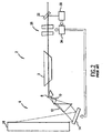
- FIG. 3 A first embodiment of the present invention is shown in FIG. 3.
- the excimer laser of this embodiment has similar line narrowing optics (including a diffraction grating) as the prior art excimer laser of FIG. 1.
- the output beam 18 is sent through a spatial filter 44 after passing through output coupler 4.
- the spatial filter 44 consists of two cylindrical focusing lenses 46 and 48 separated by a distance equal to the sum of the focal lengths of both lenses.
- the lenses have a focal length of about 20 cm and the cylinder axis is oriented in vertical direction (in and out of the plane of drawing) which is in this embodiment also the discharge direction of the laser.
- the first lens focuses the laser beam in horizontal direction but does not focus the beam in vertical direction.
- This aperture is a vertical slit whose position can be adjusted both along the beam propagation direction and across it by an X-Y adjustable mount (not shown).
- the width of the slit is preferably between 100 microns and 200 microns.
- the length of the slit in this embodiment is just slightly larger than the electrode gap, i.e., about 20 mm. Therefore, this aperture will transmit the beam originally propagating within an angle of 0.5 to 1.0 mrad in horizontal direction.
- This beam is then recollimated with a lens 48.
- lenses 46 and 48 with larger focal lengths are used, the distance between the lenses and the width of the slit 50 should be increased proportionally.
- This can be done to reduce the power density on the slit 50 and increase its lifetime.
- the lenses with different focal lengths can be used, with the position of the aperture 50 shifted proportionally to the lens with shorter focal length.
- this spatial filter not only filters out divergence of the laser beam, which is well known use of it, but it also helps to farther reduce the bandwidth of the laser. Therefore, beam 52 exiting the spatial filter 44 will have a narrowed spectral width.
- FIG. 4 shows laser spectrums of a KrF excimer laser measured by Applicant after filtering various diverging portions of the laser beam through a spatial filter.
- the focal length of each of the two lenses was 50 cm, and the slit width was 0.5 mm. Therefore, the divergence pass band of the spatial filter was about 1 mrad.
- the slit was shifted in horizontal direction across the beam with steps of 0.15 mm which corresponds to divergence steps of about 0.3 mrad.
- steps of 0.15 mm which corresponds to divergence steps of about 0.3 mrad.
- FIGS. 5 and 6 show the results of experiments conducted by Applicant using a 1.0 mrad spatial filter centered at divergent angles of -0.9, -0.6, -0.3, 0, 0.3, 0.6, and 0.9 milliradians relative to the direction of laser optical axis.
- FIG. 5 shows the 95% integral measured within the respective angular bands.
- FIG. 6 shows the percent of the beam energy measured within the respective bands. For example in the 1.0 mrad band between -0.5 mrad and +0.5 mrad, the percentage of beam energy was about 80 percent and the 95 percent integral bandwidth was 1.46 pm. This compares with the unfiltered 95 percent integral bandwidth of 2.00 pm.
- the method of the present invention compares favorably with other techniques, which can be employed to control the bandwidth of excimer laser such as by simply aperturing the outcoming beam.
- an aperture is placed in the beam path instead of spatial filter 44, which limits the beam in horizontal direction.
- FIGS. 7 and 8 show results of experimental measurements done by Applicant. The 95% integral spectral bandwidth of original beam used in these experiments was 2.00 pm. Comparing these data with the ones for the spatial filter of the present invention shows that in order to achieve the same spectral bandwidth of 1.46 pm, it is necessary to use an aperture of about 1 mm wide, which will only transmit about 35% of the original beam energy. In comparison, using the spatial filter of the present invention, more than 80% of original light is preserved.
- FIG. 9 shows a sketch of a preferred spatial filter 44.
- Filter 44 consists of two cylindrical lenses 46 and 48 with the cylinder axis oriented vertically (in and out of the drawing plane).
- the vertical slit 50 consists of two small prisms 50a and 50b with their apex edges separated by a small distance d.
- the prisms are made from fused silica or other UV transparent material.
- Both prisms 50a and 50b are held in place with a mounting means (not shown).
- the apex angle of the prism is preferably chosen in the range 10 - 60 degrees.
- the incoming light 60 is focused by lens 46 in horizontal direction.
- the portion 61 of the beam which consists of rays having directions which are within 1 mrad of the beam axis will be focused in a narrow line between the prisms 50a and 50b. That means, these rays can go through in between the prisms unaffected.
- This portion of light is then recollimated by lens 48 into the output beam 64.
- the portion of the beam 62 which consists of rays having directions which fall outside the 1 mrad range will be focused by lens 46 into either prism 50a or 50b.
- the prism will deflect the rays away from the axis as shown in FIG. 9. Therefore, these rays will be absorbed by screens 52a and b located on either side of the lens 48. Therefore, only the portion of the beam propagating within a 1.0 mrad fan of angles can go through this filter.
- the use of UV transparent material instead of opaque metal slit avoids any significant heating or possible laser ablation of the slit material.
- conventional opaque metal slit can be used as well in most situations. This slit will block (absorb and or reflect) any ray 62 whose propagation direction falls outside the selected mrad range.
- UV transparent aperture 50 can be made in the shape other than prism, such as a small radius cylinders with a radius of about 1-2 mm, half moons or others.
- FIG. 10 shows a second preferred embodiment of the present invention.
- the spatial filter 130 is placed inside the optical cavity of laser 102 defined by diffraction grating 16 and output coupler 4.
- prisms 8, 10, and 12, mirror 14, and chamber 3 have the same functions as in the first embodiment of FIG. 3.
- the principles of operation and design of the spatial filter 130 in this embodiment is the same as in the first embodiment of FIG. 3. Placement of the filter inside the laser cavity can provide increased efficiency of the laser operation, because the portions of the beam with a "bad" spectrum will be blocked from even being generated by the laser.
- spherical focusing lenses can be used instead of cylindrical lenses.
- More complex telescopic lens structure can be used in place of a single lens which was specified.
- the grating based line narrowing package could be replaced with a prism based line narrowing package, since prisms, like gratings disperse the rays of a beam according to the wavelengths of light in the beam.
- a good application for a system using prism based line narrowing with spatial filtering is for an F 2 laser.
- the laser gas in a typical F 2 laser comprises a small portion of fluorine gas and the remainder helium or neon. Therefore the reader should understand that the scope of the invention should be determined by the appended claims and their legal equivalents.
Landscapes
- Physics & Mathematics (AREA)
- Engineering & Computer Science (AREA)
- Plasma & Fusion (AREA)
- Electromagnetism (AREA)
- General Physics & Mathematics (AREA)
- Optics & Photonics (AREA)
- Lasers (AREA)
Abstract
Description
Claims (14)
- A line narrowed gas discharge laser comprising:A) a gain medium, comprising a discharge excited laser gas, for generating a laser beam;B) line narrowing optics comprising a diffraction grating based dispersive element defining a dispersion direction for dispersing into wavelength dependent directions laser light produced in said gain medium,C) a spatial filter comprising an aperture positioned to define an aperture position, and at least two focusing elements each having a focus at said aperture position; wherein said spatial filter is aligned in said laser beam so as to filter out of said beam light at wavelengths greater or smaller than a desired range of wavelengths.
- A laser as in Claim 1 wherein at least one of said two focusing elements is a cylindrical lens defining an axis having its axis aligned perpendicular to said dispersion direction.
- A laser as in Claim 1 wherein said at least two focusing elements are two cylindrical lenses, each lens defining an axis and having its axis aligned perpendicular to said dispersion direction.
- A laser as in Claim 1 wherein said aperture comprises two prisms transparent to said laser beam.
- A laser as in Claim 1 wherein said aperture is a rectangular slit in a material opaque to said beam.
- A laser system as in Claim 1 wherein said system comprises optical elements defining a resonance cavity and said spatial filter is located outside said resonance cavity.
- A laser system as in Claim 1 wherein said system comprises optical elements defining a resonance cavity and said spatial filter is located inside said resonance cavity.
- A laser as in Claim 1 wherein said dispersive element in a grating.
- A laser as in Claim 1 wherein said grating is arranged in a Littrow configuration.
- A laser as in Claim 1 wherein said line narrowing optics comprises a beam expander.
- A laser as in Claim 10 wherein said beam expander comprises a plurality of prisms.
- A line narrowed gas discharge laser comprising:A) a gain medium, comprising a discharge excited laser gas, for generating a laser beam;B) line narrowing optics comprising a prism based dispersive element defining a dispersion direction for dispersing into wavelength dependent directions laser light produced in said gain medium,C) a spatial filter comprising an aperture positioned to define an aperture position, and at least two focusing elements each having a focus at said aperture position; wherein said spatial filter is aligned in said laser beam so as to filter out of said beam light at wavelengths greater or smaller than a desired range of wavelengths.
- A laser as in Claim 12 wherein said laser is an F2 laser.
- A laser as in Claim 13 wherein said laser gas comprises fluorine and helium or neon.
Applications Claiming Priority (2)
| Application Number | Priority Date | Filing Date | Title |
|---|---|---|---|
| US09/309,478 US6556612B2 (en) | 1999-05-10 | 1999-05-10 | Line narrowed laser with spatial filter |
| US309478 | 1999-05-10 |
Publications (3)
| Publication Number | Publication Date |
|---|---|
| EP1054490A2 true EP1054490A2 (en) | 2000-11-22 |
| EP1054490A3 EP1054490A3 (en) | 2001-01-24 |
| EP1054490B1 EP1054490B1 (en) | 2004-07-28 |
Family
ID=23198405
Family Applications (1)
| Application Number | Title | Priority Date | Filing Date |
|---|---|---|---|
| EP00109628A Expired - Lifetime EP1054490B1 (en) | 1999-05-10 | 2000-05-05 | Line narrowed laser with spatial filter |
Country Status (5)
| Country | Link |
|---|---|
| US (1) | US6556612B2 (en) |
| EP (1) | EP1054490B1 (en) |
| JP (1) | JP2001044549A (en) |
| AT (1) | ATE272259T1 (en) |
| DE (1) | DE60012420T2 (en) |
Cited By (2)
| Publication number | Priority date | Publication date | Assignee | Title |
|---|---|---|---|---|
| US9905990B1 (en) | 2014-04-17 | 2018-02-27 | Alakai Defense Systems, Inc. | Background removal from Raman spectra by an intracavity active-tuning element for a laser |
| CN112462464A (en) * | 2020-11-25 | 2021-03-09 | 上海思量量子科技有限公司 | Cascadable filtering system and photon filtering method thereof |
Families Citing this family (18)
| Publication number | Priority date | Publication date | Assignee | Title |
|---|---|---|---|---|
| US20020127497A1 (en) * | 1998-09-10 | 2002-09-12 | Brown Daniel J. W. | Large diffraction grating for gas discharge laser |
| US7856044B2 (en) | 1999-05-10 | 2010-12-21 | Cymer, Inc. | Extendable electrode for gas discharge laser |
| US6801560B2 (en) * | 1999-05-10 | 2004-10-05 | Cymer, Inc. | Line selected F2 two chamber laser system |
| JP3365500B2 (en) * | 2000-01-19 | 2003-01-14 | ウシオ電機株式会社 | Narrow band ArF excimer laser device |
| US6928093B2 (en) * | 2002-05-07 | 2005-08-09 | Cymer, Inc. | Long delay and high TIS pulse stretcher |
| US7088758B2 (en) | 2001-07-27 | 2006-08-08 | Cymer, Inc. | Relax gas discharge laser lithography light source |
| US7671349B2 (en) * | 2003-04-08 | 2010-03-02 | Cymer, Inc. | Laser produced plasma EUV light source |
| JP4334261B2 (en) * | 2003-04-08 | 2009-09-30 | ウシオ電機株式会社 | Two-stage laser equipment for exposure |
| US20050286599A1 (en) * | 2004-06-29 | 2005-12-29 | Rafac Robert J | Method and apparatus for gas discharge laser output light coherency reduction |
| US9018561B2 (en) | 2007-05-23 | 2015-04-28 | Cymer, Llc | High power seed/amplifier laser system with beam shaping intermediate the seed and amplifier |
| US20090034576A1 (en) * | 2007-08-03 | 2009-02-05 | Newport Corporation | Linewidth-narrowed excimer laser cavity |
| US7655925B2 (en) * | 2007-08-31 | 2010-02-02 | Cymer, Inc. | Gas management system for a laser-produced-plasma EUV light source |
| US7812329B2 (en) * | 2007-12-14 | 2010-10-12 | Cymer, Inc. | System managing gas flow between chambers of an extreme ultraviolet (EUV) photolithography apparatus |
| US8519366B2 (en) * | 2008-08-06 | 2013-08-27 | Cymer, Inc. | Debris protection system having a magnetic field for an EUV light source |
| DE102008050869A1 (en) * | 2008-09-30 | 2009-11-26 | Carl Zeiss Laser Optics Gmbh | Optical device for enlarging adjustment range of laser beam spectral bandwidth of laser light source, comprises beam enlargement module which enlarges laser beam, where optical arrangement comprises optical component |
| JP5687488B2 (en) | 2010-02-22 | 2015-03-18 | ギガフォトン株式会社 | Extreme ultraviolet light generator |
| NL2006747A (en) * | 2010-07-26 | 2012-01-30 | Asml Netherlands Bv | Imprint lithography alignment method and apparatus. |
| US10416471B2 (en) * | 2016-10-17 | 2019-09-17 | Cymer, Llc | Spectral feature control apparatus |
Family Cites Families (19)
| Publication number | Priority date | Publication date | Assignee | Title |
|---|---|---|---|---|
| DE295957C (en) | ||||
| US4549144A (en) * | 1983-08-31 | 1985-10-22 | The United States Of America As Represented By The United States Department Of Energy | Reflex ring laser amplifier system |
| US4649544A (en) * | 1984-10-19 | 1987-03-10 | The United States Of America As Represented By The United States Department Of Energy | Electro-optic harmonic conversion to switch a laser beam out of a cavity |
| JPH01225186A (en) * | 1988-03-03 | 1989-09-08 | Mitsubishi Electric Corp | Narrow band laser |
| DD295957A5 (en) * | 1988-06-07 | 1991-11-14 | Friedrich-Schiller-Universitaet Jena,De | ARRANGEMENT FOR GENERATING HARD-ROLLED LASER RADIATION HIGH PERFORMANCE PREFERABLY FOR LASERS WITH ACTIVE VOLUME OF RECTANGULAR CROSS-SECTION |
| US5050174A (en) * | 1989-02-14 | 1991-09-17 | Matsushita Electric Industrial Co., Ltd. | Laser device |
| JP3360078B2 (en) | 1990-02-28 | 2002-12-24 | 株式会社小松製作所 | Narrow band oscillation laser |
| IT1238711B (en) * | 1990-04-13 | 1993-09-01 | Galileo Spa Off | METHOD AND INTERFEROMETRIC SYSTEM WITH FRINGES CODED FOR DETECTION OF THE WAVE FRONT IN OPTICS. |
| JPH05152666A (en) | 1991-11-27 | 1993-06-18 | Mitsubishi Electric Corp | Narrowed-band laser |
| US5386426A (en) * | 1992-09-10 | 1995-01-31 | Hughes Aircraft Company | Narrow bandwidth laser array system |
| US5298971A (en) * | 1992-09-23 | 1994-03-29 | Industrial Technology Research Institute | Lateral shear interferometer for testing aspheric surfaces |
| WO1995022187A1 (en) * | 1994-02-15 | 1995-08-17 | Coherent, Inc. | System for minimizing the depolarization of a laser beam due to thermally induced birefringence |
| WO1996031929A1 (en) | 1995-04-03 | 1996-10-10 | Komatsu Ltd. | Narrow-band laser |
| US6331994B1 (en) | 1996-07-19 | 2001-12-18 | Canon Kabushiki Kaisha | Excimer laser oscillation apparatus and method, excimer laser exposure apparatus, and laser tube |
| JP3958819B2 (en) | 1997-01-31 | 2007-08-15 | ミネベア株式会社 | Method of driving a two-phase claw pole type stepping motor used in a recording disk driving device of an information storage device |
| US5835520A (en) | 1997-04-23 | 1998-11-10 | Cymer, Inc. | Very narrow band KrF laser |
| US6137821A (en) * | 1997-06-04 | 2000-10-24 | Cymer, Inc. | Durable etalon based output coupler |
| US5856991A (en) | 1997-06-04 | 1999-01-05 | Cymer, Inc. | Very narrow band laser |
| JP4117856B2 (en) * | 1997-12-12 | 2008-07-16 | 株式会社小松製作所 | Narrow-band oscillation excimer laser and fluoride prism |
-
1999
- 1999-05-10 US US09/309,478 patent/US6556612B2/en not_active Expired - Lifetime
-
2000
- 2000-05-05 DE DE60012420T patent/DE60012420T2/en not_active Expired - Fee Related
- 2000-05-05 EP EP00109628A patent/EP1054490B1/en not_active Expired - Lifetime
- 2000-05-05 AT AT00109628T patent/ATE272259T1/en not_active IP Right Cessation
- 2000-05-10 JP JP2000177586A patent/JP2001044549A/en active Pending
Cited By (2)
| Publication number | Priority date | Publication date | Assignee | Title |
|---|---|---|---|---|
| US9905990B1 (en) | 2014-04-17 | 2018-02-27 | Alakai Defense Systems, Inc. | Background removal from Raman spectra by an intracavity active-tuning element for a laser |
| CN112462464A (en) * | 2020-11-25 | 2021-03-09 | 上海思量量子科技有限公司 | Cascadable filtering system and photon filtering method thereof |
Also Published As
| Publication number | Publication date |
|---|---|
| ATE272259T1 (en) | 2004-08-15 |
| JP2001044549A (en) | 2001-02-16 |
| DE60012420T2 (en) | 2004-12-16 |
| US6556612B2 (en) | 2003-04-29 |
| US20020034209A1 (en) | 2002-03-21 |
| EP1054490A3 (en) | 2001-01-24 |
| EP1054490B1 (en) | 2004-07-28 |
| DE60012420D1 (en) | 2004-09-02 |
Similar Documents
| Publication | Publication Date | Title |
|---|---|---|
| EP1054490B1 (en) | Line narrowed laser with spatial filter | |
| US6154470A (en) | Molecular fluorine (F2) laser with narrow spectral linewidth | |
| US6240110B1 (en) | Line narrowed F2 laser with etalon based output coupler | |
| US6101211A (en) | Narrow-band laser apparatus | |
| US6750972B2 (en) | Gas discharge ultraviolet wavemeter with enhanced illumination | |
| US6487228B2 (en) | Narrow band excimer or molecular fluorine laser with adjustable bandwidth | |
| US6678291B2 (en) | Molecular fluorine laser | |
| US20020186741A1 (en) | Very narrow band excimer or molecular fluorine laser | |
| US6061129A (en) | Compact high resolution grating spectrometer | |
| EP1240694B1 (en) | Line narrowed laser with bidirection beam expansion | |
| US6834069B1 (en) | Molecular fluorine laser with intracavity polarization enhancer | |
| EP1119083A2 (en) | Narrow beam ArF excimer laser device | |
| CN111934183A (en) | Device and method for actively controlling linewidth and E95 of excimer laser | |
| US10965087B2 (en) | Laser device | |
| WO2010127831A1 (en) | Bandwidth narrowing module for setting a spectral bandwidth of a laser beam | |
| JP2001203416A (en) | Laser system | |
| JP2004140265A (en) | Narrow-band laser apparatus | |
| US6476987B1 (en) | Excimer laser with line narrowing | |
| RU2177196C1 (en) | Unstable resonator | |
| JP2006339358A (en) | Narrow-band laser device | |
| WO2001041269A1 (en) | Very narrow band excimer or molecular fluorine laser | |
| Onkels et al. | Advanced VUV spectrometer for F2 laser metrology | |
| JPH0491483A (en) | Gas laser oscillator |
Legal Events
| Date | Code | Title | Description |
|---|---|---|---|
| PUAI | Public reference made under article 153(3) epc to a published international application that has entered the european phase |
Free format text: ORIGINAL CODE: 0009012 |
|
| AK | Designated contracting states |
Kind code of ref document: A2 Designated state(s): AT BE CH CY DE DK ES FI FR GB GR IE IT LI LU MC NL PT SE |
|
| AX | Request for extension of the european patent |
Free format text: AL;LT;LV;MK;RO;SI |
|
| PUAL | Search report despatched |
Free format text: ORIGINAL CODE: 0009013 |
|
| AK | Designated contracting states |
Kind code of ref document: A3 Designated state(s): AT BE CH CY DE DK ES FI FR GB GR IE IT LI LU MC NL PT SE |
|
| AX | Request for extension of the european patent |
Free format text: AL;LT;LV;MK;RO;SI |
|
| 17P | Request for examination filed |
Effective date: 20010216 |
|
| 17Q | First examination report despatched |
Effective date: 20010405 |
|
| AKX | Designation fees paid |
Free format text: AT BE CH CY DE DK ES FI FR GB GR IE IT LI LU MC NL PT SE |
|
| GRAP | Despatch of communication of intention to grant a patent |
Free format text: ORIGINAL CODE: EPIDOSNIGR1 |
|
| GRAS | Grant fee paid |
Free format text: ORIGINAL CODE: EPIDOSNIGR3 |
|
| RAP1 | Party data changed (applicant data changed or rights of an application transferred) |
Owner name: CYMER, INC. |
|
| GRAA | (expected) grant |
Free format text: ORIGINAL CODE: 0009210 |
|
| AK | Designated contracting states |
Kind code of ref document: B1 Designated state(s): AT BE CH CY DE DK ES FI FR GB GR IE IT LI LU MC NL PT SE |
|
| PG25 | Lapsed in a contracting state [announced via postgrant information from national office to epo] |
Ref country code: IT Free format text: LAPSE BECAUSE OF FAILURE TO SUBMIT A TRANSLATION OF THE DESCRIPTION OR TO PAY THE FEE WITHIN THE PRE;WARNING: LAPSES OF ITALIAN PATENTS WITH EFFECTIVE DATE BEFORE 2007 MAY HAVE OCCURRED AT ANY TIME BEFORE 2007. THE CORRECT EFFECTIVE DATE MAY BE DIFFERENT FROM THE ONE RECORDED.SCRIBED TIME-LIMIT Effective date: 20040728 Ref country code: LI Free format text: LAPSE BECAUSE OF FAILURE TO SUBMIT A TRANSLATION OF THE DESCRIPTION OR TO PAY THE FEE WITHIN THE PRESCRIBED TIME-LIMIT Effective date: 20040728 Ref country code: CH Free format text: LAPSE BECAUSE OF FAILURE TO SUBMIT A TRANSLATION OF THE DESCRIPTION OR TO PAY THE FEE WITHIN THE PRESCRIBED TIME-LIMIT Effective date: 20040728 Ref country code: FI Free format text: LAPSE BECAUSE OF FAILURE TO SUBMIT A TRANSLATION OF THE DESCRIPTION OR TO PAY THE FEE WITHIN THE PRESCRIBED TIME-LIMIT Effective date: 20040728 Ref country code: BE Free format text: LAPSE BECAUSE OF FAILURE TO SUBMIT A TRANSLATION OF THE DESCRIPTION OR TO PAY THE FEE WITHIN THE PRESCRIBED TIME-LIMIT Effective date: 20040728 Ref country code: AT Free format text: LAPSE BECAUSE OF FAILURE TO SUBMIT A TRANSLATION OF THE DESCRIPTION OR TO PAY THE FEE WITHIN THE PRESCRIBED TIME-LIMIT Effective date: 20040728 |
|
| REG | Reference to a national code |
Ref country code: GB Ref legal event code: FG4D |
|
| REG | Reference to a national code |
Ref country code: CH Ref legal event code: EP |
|
| REG | Reference to a national code |
Ref country code: IE Ref legal event code: FG4D |
|
| REF | Corresponds to: |
Ref document number: 60012420 Country of ref document: DE Date of ref document: 20040902 Kind code of ref document: P |
|
| PG25 | Lapsed in a contracting state [announced via postgrant information from national office to epo] |
Ref country code: DK Free format text: LAPSE BECAUSE OF FAILURE TO SUBMIT A TRANSLATION OF THE DESCRIPTION OR TO PAY THE FEE WITHIN THE PRESCRIBED TIME-LIMIT Effective date: 20041028 Ref country code: GR Free format text: LAPSE BECAUSE OF FAILURE TO SUBMIT A TRANSLATION OF THE DESCRIPTION OR TO PAY THE FEE WITHIN THE PRESCRIBED TIME-LIMIT Effective date: 20041028 Ref country code: SE Free format text: LAPSE BECAUSE OF FAILURE TO SUBMIT A TRANSLATION OF THE DESCRIPTION OR TO PAY THE FEE WITHIN THE PRESCRIBED TIME-LIMIT Effective date: 20041028 |
|
| PG25 | Lapsed in a contracting state [announced via postgrant information from national office to epo] |
Ref country code: ES Free format text: LAPSE BECAUSE OF FAILURE TO SUBMIT A TRANSLATION OF THE DESCRIPTION OR TO PAY THE FEE WITHIN THE PRESCRIBED TIME-LIMIT Effective date: 20041108 |
|
| ET | Fr: translation filed | ||
| REG | Reference to a national code |
Ref country code: CH Ref legal event code: PL |
|
| PG25 | Lapsed in a contracting state [announced via postgrant information from national office to epo] |
Ref country code: LU Free format text: LAPSE BECAUSE OF NON-PAYMENT OF DUE FEES Effective date: 20050505 Ref country code: IE Free format text: LAPSE BECAUSE OF NON-PAYMENT OF DUE FEES Effective date: 20050505 Ref country code: CY Free format text: LAPSE BECAUSE OF FAILURE TO SUBMIT A TRANSLATION OF THE DESCRIPTION OR TO PAY THE FEE WITHIN THE PRESCRIBED TIME-LIMIT Effective date: 20050505 |
|
| PG25 | Lapsed in a contracting state [announced via postgrant information from national office to epo] |
Ref country code: MC Free format text: LAPSE BECAUSE OF NON-PAYMENT OF DUE FEES Effective date: 20050531 |
|
| PLBE | No opposition filed within time limit |
Free format text: ORIGINAL CODE: 0009261 |
|
| STAA | Information on the status of an ep patent application or granted ep patent |
Free format text: STATUS: NO OPPOSITION FILED WITHIN TIME LIMIT |
|
| 26N | No opposition filed |
Effective date: 20050429 |
|
| REG | Reference to a national code |
Ref country code: IE Ref legal event code: MM4A |
|
| PG25 | Lapsed in a contracting state [announced via postgrant information from national office to epo] |
Ref country code: PT Free format text: LAPSE BECAUSE OF NON-PAYMENT OF DUE FEES Effective date: 20041228 |
|
| PGFP | Annual fee paid to national office [announced via postgrant information from national office to epo] |
Ref country code: DE Payment date: 20080630 Year of fee payment: 9 |
|
| PGFP | Annual fee paid to national office [announced via postgrant information from national office to epo] |
Ref country code: GB Payment date: 20080529 Year of fee payment: 9 |
|
| GBPC | Gb: european patent ceased through non-payment of renewal fee |
Effective date: 20090505 |
|
| REG | Reference to a national code |
Ref country code: FR Ref legal event code: ST Effective date: 20100129 |
|
| PG25 | Lapsed in a contracting state [announced via postgrant information from national office to epo] |
Ref country code: FR Free format text: LAPSE BECAUSE OF NON-PAYMENT OF DUE FEES Effective date: 20090602 |
|
| PGFP | Annual fee paid to national office [announced via postgrant information from national office to epo] |
Ref country code: FR Payment date: 20080519 Year of fee payment: 9 |
|
| PG25 | Lapsed in a contracting state [announced via postgrant information from national office to epo] |
Ref country code: GB Free format text: LAPSE BECAUSE OF NON-PAYMENT OF DUE FEES Effective date: 20090505 |
|
| PG25 | Lapsed in a contracting state [announced via postgrant information from national office to epo] |
Ref country code: DE Free format text: LAPSE BECAUSE OF NON-PAYMENT OF DUE FEES Effective date: 20091201 |
|
| REG | Reference to a national code |
Ref country code: NL Ref legal event code: PD Owner name: KONA TECHNOLOGIES LLC; US Free format text: DETAILS ASSIGNMENT: VERANDERING VAN EIGENAAR(S), SAMENVOEGEN; FORMER OWNER NAME: CYMER, INC. Effective date: 20160930 Ref country code: NL Ref legal event code: HC Owner name: CYMER LLC; US Free format text: DETAILS ASSIGNMENT: VERANDERING VAN EIGENAAR(S), VERANDERING VAN NAAM VAN DE EIGENAAR(S); FORMER OWNER NAME: KONA TECHNOLOGIES LLC Effective date: 20160930 |
|
| PGFP | Annual fee paid to national office [announced via postgrant information from national office to epo] |
Ref country code: NL Payment date: 20190521 Year of fee payment: 20 |
|
| REG | Reference to a national code |
Ref country code: NL Ref legal event code: MK Effective date: 20200504 |