EP1054439A1 - Gripper for supporting substrate in a vertical orientation - Google Patents
Gripper for supporting substrate in a vertical orientation Download PDFInfo
- Publication number
- EP1054439A1 EP1054439A1 EP00303904A EP00303904A EP1054439A1 EP 1054439 A1 EP1054439 A1 EP 1054439A1 EP 00303904 A EP00303904 A EP 00303904A EP 00303904 A EP00303904 A EP 00303904A EP 1054439 A1 EP1054439 A1 EP 1054439A1
- Authority
- EP
- European Patent Office
- Prior art keywords
- substrate
- pair
- opposed surfaces
- end effectors
- gripper
- Prior art date
- Legal status (The legal status is an assumption and is not a legal conclusion. Google has not performed a legal analysis and makes no representation as to the accuracy of the status listed.)
- Withdrawn
Links
Images




Classifications
-
- H—ELECTRICITY
- H10—SEMICONDUCTOR DEVICES; ELECTRIC SOLID-STATE DEVICES NOT OTHERWISE PROVIDED FOR
- H10P—GENERIC PROCESSES OR APPARATUS FOR THE MANUFACTURE OR TREATMENT OF DEVICES COVERED BY CLASS H10
- H10P72/00—Handling or holding of wafers, substrates or devices during manufacture or treatment thereof
- H10P72/70—Handling or holding of wafers, substrates or devices during manufacture or treatment thereof for supporting or gripping
- H10P72/76—Handling or holding of wafers, substrates or devices during manufacture or treatment thereof for supporting or gripping using mechanical means, e.g. clamps or pinches
- H10P72/7602—Handling or holding of wafers, substrates or devices during manufacture or treatment thereof for supporting or gripping using mechanical means, e.g. clamps or pinches the wafers being placed on a robot blade or gripped by a gripper for conveyance
-
- Y—GENERAL TAGGING OF NEW TECHNOLOGICAL DEVELOPMENTS; GENERAL TAGGING OF CROSS-SECTIONAL TECHNOLOGIES SPANNING OVER SEVERAL SECTIONS OF THE IPC; TECHNICAL SUBJECTS COVERED BY FORMER USPC CROSS-REFERENCE ART COLLECTIONS [XRACs] AND DIGESTS
- Y10—TECHNICAL SUBJECTS COVERED BY FORMER USPC
- Y10S—TECHNICAL SUBJECTS COVERED BY FORMER USPC CROSS-REFERENCE ART COLLECTIONS [XRACs] AND DIGESTS
- Y10S414/00—Material or article handling
- Y10S414/135—Associated with semiconductor wafer handling
- Y10S414/141—Associated with semiconductor wafer handling includes means for gripping wafer
Definitions
- This invention relates to methods of handling vertically oriented substrates and to gripper assemblies for handling substrates.
- substrate handler reliability When designing an automated semiconductor substrate handler, three main concerns prevail; 1) substrate handler reliability; 2) substrate handler particle generation and potential for substrate contamination; and 3) substrate handler size. Each of these concerns is essentially aimed at reducing costs associated with damaged or defective substrates. Increasing substrate handler reliability prevents substrate damage which can occur when a substrate is incorrectly grasped, etc., and prevents downtime associated with repair and/or recalibration. Reducing particle generation helps reduce defects which result when particles contact substrate surfaces, and reducing substrate handler size allows processing chamber openings to be smaller and to thereby reduce the possibility of particle entry to the chamber and the possibility of substrate contamination thereby.
- a major source of particles results when a substrate slides along the surface of the substrate handler's end effector. Accordingly, after a wafer is placed/loaded onto an end effector, a pin or other holding mechanism conventionally moves into place to secure the substrate and prevent the substrate from sliding against the end effector during transport. However sliding and the particles that result therefrom, may occur as part of the loading process. Further, the holding mechanisms, being moving parts themselves, can generate particles and can introduce reliability issues, increasing substrate handler costs. Moreover, during the entire load and transfer process, particles and other contaminants may collect on the substrate or between the end effectors and the substrate.
- Such a substrate handler and end effector should be streamlined, and should reduce the probability of contaminant contact with substrate surfaces and/or the probability of trapped contaminants between the end effector and the substrate.
- the present invention provides an inventive gripper assembly having a pair of fingers operatively coupled to the gripper so as to move between an open and a closed position; each finger has an end effector coupled thereto, and adapted to support a vertically oriented substrate therebetween.
- Each end effector has a first pair of opposed surfaces and a second pair of opposed surfaces. Each pair of opposed surfaces is adapted either to simultaneously contact the edge of a vertically oriented substrate supported by the end effector, (clamp-type contact) or to limit horizontal movement of a vertically oriented substrate supported by the end effectors (pocket-type contact).
- Each of the opposed surfaces preferably does not move relative to the other.
- a pair of opposed surfaces that do not move relative to each other is referred to herein as unitary, whether made of one or more pieces.
- both the first and second opposed surfaces are radiused to mimic the circumference of the wafer so as to deter fluid and contaminants from collecting between the substrate and the surfaces of the end effector.
- the end effectors are positioned on opposite sides of a vertically oriented substrate, and preferably pick up or grasp the substrate in either of the two manners described below. Specifically, in the case of a gripper assembly configured for clamp-type contact, the end effectors are moved to a position at which the end effectors may stabily support the vertically oriented substrate. Thereafter, the end effectors are closed such that the end effector's first and second pairs of opposed surfaces contact the substrate's edge and thereby support the substrate.
- the gripper assembly may simply close such that the two pairs of opposed surfaces positioned closest to the bottom edge of the substrate contact the substrate.
- the pocket-type end effectors may move to a position in line with the substrate, yet at an elevation below which the pair of opposed surfaces would contact the substrate when the end effectors are in a closed position. This elevation may be entirely below the substrate or anywhere below the substrate's horizontal diameter. Thereafter the closed pair of end effectors are elevated such that the end effectores' lower price of opposed surfaces contact and support the substrate via the substrate's edges.
- a pocket type gripper need not have an open and closed position, as the gripper may pick up and deposit a substrate by raising and lowering around the substrate as will be apparent with reference to the detailed description of the preferred embodiments.
- the clamp-type gripper is advantageous because it is able to grasp wafers that are within a relatively wide tolerance of a desired position, and thus reduces the time required for initial robot calibration and chamber alignment, as well as reducing the frequency and time required for recalibration and alignment.
- the pocket-type gripper is advantageous because it reduces the risk of substrate damage.
- the pocket-type grippers close below the substrate forming a pocket, and then elevate such that the substrate gently contacts the bottom of the pocket (e.g., contacts the lower pair of opposed surfaces), and such that the upper pair of opposed surfaces surround the substrate and prevent the substrate from excessive tilting in the horizontal direction. Accordingly, the only force applied to the substrate is a purely vertical lifting force, which tends to generate fewer particles than do multidirectional forces. Further, because there is no external force opposing the vertical lifting force, the substrate is not acted on by external opposing forces, and is less likely to be damaged.
- the fingers are preferably bent such that the gripper is positioned to the front, back or most preferably the side of the substrate rather than directly above the substrate.
- particles from the gripper are less likely to contaminate the substrate.
- the end effectors of the inventive gripper assembly preferably have no moving parts, and are therefore inexpensive and less likely to malfunction. Further, the absence of moving parts enable a streamlined design, which in addition to the fact that the gripper assembly grasps a substrate by the substrate's edges, allows the inventive gripper assembly to move substrates through narrow openings such as those found in semiconductor manufacturing equipment.
- a substrate handler employing the inventive gripper assembly is ideally suited for semiconductor applications. Moreover, because the inventive gripper assembly supports a substrate in a vertical orientation, contaminants are less likely to collect on the substrate's surfaces. Further contamination reduction may be achieved with the use of radiused end effector surfaces which are radiused to mimic the circumference of the wafer, and thus may minimize or eliminate contact with the front or back surface of the wafer and may contact only the beveled edge of the wafer.
- FIG. 1 is a side perspective view of a clamp-type end effector 11 of a first aspect of the inventive gripper assembly.
- the clamp-type end effector 11 comprises a first pair of opposed surfaces 13a-b, adapted to simultaneously contact an edge of a vertically oriented substrate to be supported thereby (FIGS. 2A-B), and a second pair of opposed surfaces 15a-b adapted to simultaneously contact a vertically oriented substrate to be supported thereby.
- the first pair of opposed surfaces 13a-b and the second pair of opposed surfaces 15a-b preferably comprise a groove adapted to support a substrate with minimum contact (e.g., via two opposing points), such as a "v" shaped groove.
- the first pair of opposed surfaces 13a-b and the second pair of opposed surfaces 15a-b are radiused to mimic the circumference of the wafer, and thus may minimize or eliminate contact with the front or back surface of the wafer and may contact only the beveled edge of the wafer, as shown in FIG. 1.
- the first pair of opposed surfaces 13a-b and the second pair of opposed surfaces 15a-b are preferably unitary, thereby minimizing moving parts.
- the first pair of opposed surfaces 13a-b and the second pair of opposed surfaces 15a-b preferably extend the same (with reference to FIG. 1 horizontal distance) distance x and the same (with reference to FIG. 1 vertical distance) distance y, from a point C which is to be centered on the substrate's diameter (e.g., in the configuration shown the point C is to be centered on the substrate's horizontal diameter), such that when the point C is centered along the diameter of a substrate (where the clamp-type end effector 11 provides maximum stability) the first pair of opposed surfaces 13a-b and the second pair of opposed surfaces 15a-b provide the only contact points with the substrate, and for maximum stability, contact the substrate at equal distances from the substrate's diameter, as shown in FIGS. 2A-B.
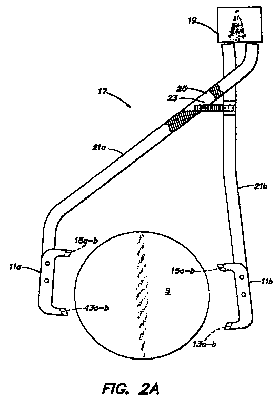
- FIGS. 2A-B are front elevational views of a gripper assembly 17 which employs a pair of the end effector 11 of FIG. 1, and which show the gripper assembly 17 in an open and a closed position, respectively.
- the gripper assembly 17 comprises a gripper 19, a pair of fingers 21a-b operatively coupled to the gripper 19 so that the gripper 19 can move the pair of fingers 21a-b between an open and a closed position. Coupled to the ends of the pair of fingers 21a-b opposite the gripper 19, are a pair of clamp-type end effectors 11a-b, configured as described with reference to FIG. 1.
- the clamp-type end effectors 11a-b are coupled to the pair of fingers 21a-b so that the first end effector 11a's first pair of opposed surfaces 13a-b and second pair of opposed surfaces 15a-b are opposite the second end effector 11b's first pair of opposed surfaces 13a-b and second pair of opposed surfaces 15a-b, respectively.
- Grippers for moving a pair of fingers between open and closed positions are well known in the art, and are therefore not described in detail herein.
- the pair of fingers 21a-b may be coupled in any manner to achieve open and closed positions.
- the distance between the clamp-type end effectors 11a-b in the open and closed position can be easily adjusted via a set screw 23 which controls relative movement between the pair of fingers 21a-b by sliding back and forth within a slot 25, as is known in the art.
- the gripper 19 moves the base of the pair of fingers 21a-b apart, causing the ends of the pair of fingers 21a-b to move apart thereby assuming an open position wherein the first pair of opposed surfaces 13a-b and the second pair of opposed surfaces 15a-b are positioned farther apart than the diameter of a substrate supported thereby (as shown in FIG. 2A).
- the gripper 19 moves the base of the pair of fingers 21a-b toward each other, causing the ends of the pair of fingers 21a-b to move toward each other to a position where the first pair of opposed surfaces 13a-b and the second pair of opposed surfaces 15-a-b are positioned such that each of the first pair of opposed surfaces 13a-b and each of the second pair of opposed surfaces 15a-b contact the substrate S (as shown in FIG. 2B).
- the lower of the two first pairs and the two second pairs of opposed surfaces are positioned where the substrate S is narrower than at its diameter (e.g., below the substrate's horizontal diameter or adjacent but off-set from the substrate's vertical diameter, etc.)
- the substrate S cannot slide downwardly through the lower pair of opposed surfaces (e.g., with reference to FIG. 2 the first pair of opposed surfaces 13a-b).
- a substrate handler (not shown) having the gripper assembly 17 coupled thereto, moves the gripper assembly 17 to a position at which the clamp-type end effectors 11a-b can stabily support the vertically oriented substrate S.
- the position at which the first pair of opposed surfaces 13a-b and the second pair of opposed surfaces 15a-b can stabily support the substrate S varies depending on the specific configuration of the first pair of opposed surfaces 13a-b and the second pair of opposed surfaces 15a-b (e.g., the distances x and y to which the first pair of opposed surfaces 13a-b and the second pair of opposed surfaces 15a-b extend, whether equal or differing distances, etc.).
- the position at which the clamp-type end effectors 11a-b can stabily support the substrate S preferably positions the center C of the clamp-type end effector 11a-b at the diameter of the substrate S (e.g., as shown in FIGS. 2A-B the horizontal diameter).
- the gripper assembly 17 assumes the closed position such that the first pair of opposed surfaces 13a-b and the second pair of opposed surfaces 15a-b each contact the edge of the substrate S and the substrate S is supported thereby.
- the clamp-type gripper assembly of FIGS. 2A-B can support a substrate in a vertical orientation regardless of the position of the gripper relative to the substrate.
- FIGS. 2A-B By turning FIGS. 2A-B to view them from various orientations, one can view various orientations of the gripper assembly 17 which still support a vertically oriented substrate by its edges.
- the gripper assembly of FIGS. 2A-B are thus easily adaptable to transfer substrates to and from variously configured substrate supports.
- the gripper assembly 17 is preferably configured with the gripper 19 at a higher elevation than the end effectors 11a-b. Accordingly, to reduce potential substrate contamination, the fingers 21a-b are bent (e.g., as shown in FIGS.
- the fingers 21a-b may be bent so as to position the gripper 19 to the front, or preferably to the back of the substrate S.
- the clamp type gripper assembly of FIGS. 2A-B may be able to pick up a flatted substrate regardless of its oreintation, because each of the end effectors 11a-b may be sized so as to be longer than the length of a flat portion of a substrate to be gripped thereby. Accordingly at least three of the pairs of opposed surfaces 13a-b will contact a flatted substrate at any given time. Three points of contact are sufficient to securely grip a substrate.
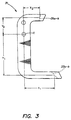
- FIG. 3 is a side perspective view of a pocket-type end effector 31 of a pocket-type aspect of the inventive gripper assembly.
- the pocket-type end effector 31 of FIG. 3 comprises a first and second pair of opposed surfaces, best described with reference to FIGS. 4A-B as a lower pair of opposed surfaces 33a-b adapted to simultaneously contact (e.g., via two opposing points) an edge of a vertically oriented substrate S to be supported thereby.
- the pocket-type gripper assembly 31 also comprises an upper pair of opposed surfaces 35a-b.
- the pocket-type gripper assembly 31 also comprises an upper pair of opposed surfaces 35a-b.
- the upper pair of opposed surfaces 35a-b are adapted to limit the horizontal movement of a vertically oriented substrate S supported by the lower pair of opposed surfaces 33a-b, rather than to clamp the substrate S.
- the upper pair of opposed surfaces 35a-b are positioned far enough apart to allow some horizontal movement (both into and out of the page).
- both the lower pair of opposed surfaces 33a-b and the upper pair of opposed surfaces 35a-b comprise a groove adapted to minimize contact with the substrate S's front and back surfaces, such as a "v" shaped grove.
- the lower pair of opposed surfaces 33a-b and/or the upper pair of opposed surfaces 35a-b are radiused to mimic the circumference of the wafer, and thus may minimize or eliminate contact with the front or back surface of the wafer and may contact only the beveled edge of the wafer, as shown in FIG. 3.
- the lower pair of opposed surfaces 33a-b and the upper pair of opposed surfaces 35a-b are preferably unitary, thereby minimizing moving parts.
- the lower pair of opposed surfaces 33a-b preferably extend a further horizontal distance (X 1 ), than do the upper pair of opposed surfaces 35a-b(X 2 ).
- the lower pair of opposed surfaces 33a-b are located a greater vertical distance Y 1 from a point C which is to be centered on the substrate S's horizontal diameter, than are the upper pair of opposed surfaces 35a-b(Y 2 ).
- a pair of pocket-type end effectors 31a-b can close when positioned along a narrower portion of the substrate S (e.g., below the elevation at which the lower pairs of opposed surfaces 33a-b contact the substrate S.
- the end effectors 31a-b elevate, the upper pair of opposed surfaces 35a-b (which do not extend inwardly as far as the lower pair of opposed surfaces 33a-b) will not contact the substrate S, as described further with reference to FIGS. 4A-B.
- the pocket-type end effectors may open and close around the substrate S from an elevation at which the lower pair of opposed surfaces will contact the substrate S when in the closed position.
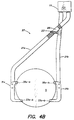
- FIGS. 4A-B are front elevational views of a gripper assembly 37 employing a pair of the end effectors of FIG. 3 and showing the gripper assembly in a closed no-substrate-contact position and closed substrate-contact position, respectively.
- the gripper assembly 37 of FIGS. 4A-C is identical to the gripper assembly 17 of FIGS. 4A-B. Accordingly, the description thereof is not repeated with reference to FIGS. 4A-B.
- a substrate handler (not shown) having the gripper assembly 37 coupled thereto, lowers the gripper assembly 37 to an elevation below an elevation at which the lower pair of opposed surfaces 33a-b would intersect the substrate S when in the closed position. Thereafter, if the gripper assembly 37 is not already closed, the gripper assembly 37 assumes the closed position such that the upper pair of opposed surfaces 35a-b close around the substrate S, but do not contact the substrate S (FIG. 4A). The substrate handler (not shown) then elevates the gripper assembly 37 causing the lower pair of opposed surfaces 33a-b to gently contact and support the substrate S in a pocket-like manner (FIG 4B).
- the force exerted between the substrate S and the lower pair of opposed surfaces 33a-b preferably is purely vertical and thus particle generation is minimized.
- the upper pair of opposed surfaces 35a-b (which are further apart than the thickness of the substrate S's edge) do not contact the substrate S unless the substrate S tilts horizontally forward or backward.
- FIG. 5 is a front elevational view of an alternative pocket-type gripper assembly 41.
- the pocket-type gripper assembly 41 is oriented such that the gripper 19 is positioned beside the substrate S. Aside from a bottom end effector 43 and a top end effector 45 the remainder of the gripper assembly 41 comprises components like those of FIGS. 1-4B. Accordingly, only those aspects of the gripper assembly 41 which differ from the gripper assemblies 17 and 37 will be described with reference to FIG. 5.
- the bottom end effector 43 is positioned such that the first and second pair of opposed surfaces 33a 1 -b 1 , 33a 2 -b 2 are in a horizontal line.
- the first and second pair of opposed surfaces 33a 1 -b 1 , 33a 2 -b 2 are configured such that both opposing surfaces simultaneously contact the substrate S to thereby support the substrate S.
- the top end effector 45 is also positioned such that the first and second pair of opposed surfaces 35a 1 -b 1 , 35a 2 -b 2 are in a horizontal line.
- the first and second pair of opposed surfaces 35a 1 -b 1 , 35a 2 -b 2 of the top end effector 45 are configured like the upper pairs of opposed surfaces 35a-b of FIGS. 4A-B.
- the first and second pair of opposed surfaces 35a 1 -b 1 , 35a 1 -b 1 of the top end effector 45 are adapted to limit the horizontal movement of a vertically oriented substrate S supported by the bottom end effector 43.
- the gripper assembly 41 assumes an open position and moves to position the center points C of the top and bottom end effector 43, 45 along the vertical diameter of the substrate S and then closes, as shown in FIG. 5.
- the bottom end effector 43 gently contacts the substrate S and lifts it from the substrate support (not shown), and the top end effector 45 lowers to an elevation wherein the opposed surfaces thereof limit the horizontal movement of the substrate S but do not clamp the substrate S (e.g., to an elevation wherein the substrate S is not inserted far enough within the groove formed by the opposed surfaces to contact the edges thereof, unless the substrate moves horizontally forward or backward).
- each of the gripper assemblies 17, 37 and 41 preferably are normally biased to a closed position (e.g., via a spring 47 shown in FIG. 5).
- the gripper assembly maintains its closed position and does not drop the substrate S.
- each of the gripper assemblies 17, 37 and 41 may be advantageously coupled to a substrate handler 51 having a moveable arm 53 for lifting and lowering the gripper assembly as shown in the schematic side view of FIG. 6.
- Such a wafer handler may be advantageously used with the end effectors described herein, and particularly with the pocket type end effectors.
- the gripper is at an elevation higher than that of the end effectors, and at least one of the fingers is bent so that the gripper is not above the substrate supported by the end effectors.
- the end effectors 11 and/or 31, rather than being unitary, may comprise moving parts which move the opposing surfaces horizontally together and apart, so as to selectively contact the substrate S.
- the clamp-type and pocket-type end effectors are preferably positioned along the diameter of the substrate S, other positions will also support the substrate.
- the lengths of the upper and lower pairs of opposed surfaces will vary according to the position at which they contact the substrate.
- the opposed surfaces need not be v-shaped, any pair of surfaces which can support the substrate may be employed.
- the invention encompasses any gripper assembly which clamps or pockets a vertically oriented substrate by contacting the substrate's edges.
- clamp type end effectors may be advantageously employed for gripping other, non-vertically oriented substrates (e.g., horizontal, etc.).
- the substrate need not slide relative to the end effectors (e.g., relative to a bottom plate of the end effector) as may occur in conventional horizontal end effectors.
- inventive end effectors are each mounted to an individual gripper finger which may move the respective end effector in a "tong" like motion rather than a pushing/sliding motion.
- the gripper actuators and gripper finger configurations disclosed herein are merely exemplary.
- the gripper fingers need not cross, as shown herein, and the gripper actuators may comprise scissors type actuators, sliding type actuators, etc.
Landscapes
- Container, Conveyance, Adherence, Positioning, Of Wafer (AREA)
- Manipulator (AREA)
Abstract
A gripper assembly (17) is provided which
supports a substrate (5) in a vertical orientation.
The gripper assembly's end effectors (11a, 11b)
contact only the edge of the substrate. In a first
aspect the end effectors each comprise a first pair or
opposed surfaces (13a-b) and an second pair of opposed
surfaces (15a-b), all of which simultaneously contact
the substrate, holding the substrate in a clamp-type
manner. The fingers (21a, 21b) to which the end
effectors are coupled, are bent so that the gripper is
not positioned above the substrate.
Description
- This invention relates to methods of handling vertically oriented substrates and to gripper assemblies for handling substrates.
- When designing an automated semiconductor substrate handler, three main concerns prevail; 1) substrate handler reliability; 2) substrate handler particle generation and potential for substrate contamination; and 3) substrate handler size. Each of these concerns is essentially aimed at reducing costs associated with damaged or defective substrates. Increasing substrate handler reliability prevents substrate damage which can occur when a substrate is incorrectly grasped, etc., and prevents downtime associated with repair and/or recalibration. Reducing particle generation helps reduce defects which result when particles contact substrate surfaces, and reducing substrate handler size allows processing chamber openings to be smaller and to thereby reduce the possibility of particle entry to the chamber and the possibility of substrate contamination thereby.
- A major source of particles results when a substrate slides along the surface of the substrate handler's end effector. Accordingly, after a wafer is placed/loaded onto an end effector, a pin or other holding mechanism conventionally moves into place to secure the substrate and prevent the substrate from sliding against the end effector during transport. However sliding and the particles that result therefrom, may occur as part of the loading process. Further, the holding mechanisms, being moving parts themselves, can generate particles and can introduce reliability issues, increasing substrate handler costs. Moreover, during the entire load and transfer process, particles and other contaminants may collect on the substrate or between the end effectors and the substrate.
- Accordingly, a need exists for an improved substrate handler, and particularly for a substrate handler having an improved end effector which will reduce substrate sliding and the associated need for moving parts to control substrate sliding. Such a substrate handler and end effector should be streamlined, and should reduce the probability of contaminant contact with substrate surfaces and/or the probability of trapped contaminants between the end effector and the substrate.
- The present invention provides an inventive gripper assembly having a pair of fingers operatively coupled to the gripper so as to move between an open and a closed position; each finger has an end effector coupled thereto, and adapted to support a vertically oriented substrate therebetween. Each end effector has a first pair of opposed surfaces and a second pair of opposed surfaces. Each pair of opposed surfaces is adapted either to simultaneously contact the edge of a vertically oriented substrate supported by the end effector, (clamp-type contact) or to limit horizontal movement of a vertically oriented substrate supported by the end effectors (pocket-type contact). Each of the opposed surfaces preferably does not move relative to the other. A pair of opposed surfaces that do not move relative to each other is referred to herein as unitary, whether made of one or more pieces. Preferably, both the first and second opposed surfaces are radiused to mimic the circumference of the wafer so as to deter fluid and contaminants from collecting between the substrate and the surfaces of the end effector.
- In operation, the end effectors are positioned on opposite sides of a vertically oriented substrate, and preferably pick up or grasp the substrate in either of the two manners described below. Specifically, in the case of a gripper assembly configured for clamp-type contact, the end effectors are moved to a position at which the end effectors may stabily support the vertically oriented substrate. Thereafter, the end effectors are closed such that the end effector's first and second pairs of opposed surfaces contact the substrate's edge and thereby support the substrate.
- Similarly, in the case of a gripper assembly configured for pocket-type contact, the gripper assembly may simply close such that the two pairs of opposed surfaces positioned closest to the bottom edge of the substrate contact the substrate. Alternatively, the pocket-type end effectors may move to a position in line with the substrate, yet at an elevation below which the pair of opposed surfaces would contact the substrate when the end effectors are in a closed position. This elevation may be entirely below the substrate or anywhere below the substrate's horizontal diameter. Thereafter the closed pair of end effectors are elevated such that the end effectores' lower price of opposed surfaces contact and support the substrate via the substrate's edges. Note that a pocket type gripper need not have an open and closed position, as the gripper may pick up and deposit a substrate by raising and lowering around the substrate as will be apparent with reference to the detailed description of the preferred embodiments.
- The clamp-type gripper is advantageous because it is able to grasp wafers that are within a relatively wide tolerance of a desired position, and thus reduces the time required for initial robot calibration and chamber alignment, as well as reducing the frequency and time required for recalibration and alignment.
- The pocket-type gripper is advantageous because it reduces the risk of substrate damage. The pocket-type grippers close below the substrate forming a pocket, and then elevate such that the substrate gently contacts the bottom of the pocket (e.g., contacts the lower pair of opposed surfaces), and such that the upper pair of opposed surfaces surround the substrate and prevent the substrate from excessive tilting in the horizontal direction. Accordingly, the only force applied to the substrate is a purely vertical lifting force, which tends to generate fewer particles than do multidirectional forces. Further, because there is no external force opposing the vertical lifting force, the substrate is not acted on by external opposing forces, and is less likely to be damaged.
- When the gripper assembly is configured such that the gripper is at a higher elevation than the end effectors, the fingers are preferably bent such that the gripper is positioned to the front, back or most preferably the side of the substrate rather than directly above the substrate. Thus, particles from the gripper are less likely to contaminate the substrate.
- The end effectors of the inventive gripper assembly, whether clamp-type or pocket-type, preferably have no moving parts, and are therefore inexpensive and less likely to malfunction. Further, the absence of moving parts enable a streamlined design, which in addition to the fact that the gripper assembly grasps a substrate by the substrate's edges, allows the inventive gripper assembly to move substrates through narrow openings such as those found in semiconductor manufacturing equipment.
- Because the inventive gripper assembly is streamlined and inexpensive, and because the gripper assembly experiences reduced calibration time, reduced particle generation, and reduced risk of substrate damage, a substrate handler employing the inventive gripper assembly is ideally suited for semiconductor applications. Moreover, because the inventive gripper assembly supports a substrate in a vertical orientation, contaminants are less likely to collect on the substrate's surfaces. Further contamination reduction may be achieved with the use of radiused end effector surfaces which are radiused to mimic the circumference of the wafer, and thus may minimize or eliminate contact with the front or back surface of the wafer and may contact only the beveled edge of the wafer.
- Other objects, features and advantages of the present invention will become more fully apparent from the following detailed description of the preferred embodiments with reference to the accompanying drawings in which:
- FIG. 1 is a side perspective view of a clamp-type end effector of a first aspect of the inventive gripper assembly;
- FIGS. 2A and 2B are front elevational views of a gripper assembly employing the clamp-type end effector of FIG. 1, showing the gripper assembly in an open and a closed position, respectively:
- FIG. 3 is a side perspective view of a pocket-type end effector of a second aspect of the inventive gripper assembly;
- FIGS. 4A-B are front elevational views of a gripper assembly employing the pocket-type end effector of FIG. 3, showing the gripper assembly in a closed no-substrate-contact position and a closed substrate-contact position, respectively; and
- FIG. 5 is a front elevational view of an alternative pocket-type gripper assembly.
-
- FIG. 1 is a side perspective view of a clamp-
type end effector 11 of a first aspect of the inventive gripper assembly. The clamp-type end effector 11 comprises a first pair ofopposed surfaces 13a-b, adapted to simultaneously contact an edge of a vertically oriented substrate to be supported thereby (FIGS. 2A-B), and a second pair ofopposed surfaces 15a-b adapted to simultaneously contact a vertically oriented substrate to be supported thereby. The first pair ofopposed surfaces 13a-b and the second pair ofopposed surfaces 15a-b preferably comprise a groove adapted to support a substrate with minimum contact (e.g., via two opposing points), such as a "v" shaped groove. Preferably, to deter particles and fluid contaminants from being trapped between the first pair ofopposed surfaces 13a-b and/or the second pair ofopposed surfaces 15a-b, and the substrate surface, the first pair ofopposed surfaces 13a-b and the second pair ofopposed surfaces 15a-b are radiused to mimic the circumference of the wafer, and thus may minimize or eliminate contact with the front or back surface of the wafer and may contact only the beveled edge of the wafer, as shown in FIG. 1. Further, the first pair ofopposed surfaces 13a-b and the second pair ofopposed surfaces 15a-b are preferably unitary, thereby minimizing moving parts. - The first pair of
opposed surfaces 13a-b and the second pair ofopposed surfaces 15a-b preferably extend the same (with reference to FIG. 1 horizontal distance) distance x and the same (with reference to FIG. 1 vertical distance) distance y, from a point C which is to be centered on the substrate's diameter (e.g., in the configuration shown the point C is to be centered on the substrate's horizontal diameter), such that when the point C is centered along the diameter of a substrate (where the clamp-type end effector 11 provides maximum stability) the first pair ofopposed surfaces 13a-b and the second pair ofopposed surfaces 15a-b provide the only contact points with the substrate, and for maximum stability, contact the substrate at equal distances from the substrate's diameter, as shown in FIGS. 2A-B. - FIGS. 2A-B are front elevational views of a
gripper assembly 17 which employs a pair of theend effector 11 of FIG. 1, and which show thegripper assembly 17 in an open and a closed position, respectively. Thegripper assembly 17 comprises agripper 19, a pair offingers 21a-b operatively coupled to thegripper 19 so that thegripper 19 can move the pair offingers 21a-b between an open and a closed position. Coupled to the ends of the pair offingers 21a-b opposite thegripper 19, are a pair of clamp-type end effectors 11a-b, configured as described with reference to FIG. 1. The clamp-type end effectors 11a-b are coupled to the pair offingers 21a-b so that thefirst end effector 11a's first pair ofopposed surfaces 13a-b and second pair ofopposed surfaces 15a-b are opposite thesecond end effector 11b's first pair ofopposed surfaces 13a-b and second pair ofopposed surfaces 15a-b, respectively. - Grippers for moving a pair of fingers between open and closed positions are well known in the art, and are therefore not described in detail herein. Similarly, although shown in a scissors linkage configuration, the pair of
fingers 21a-b may be coupled in any manner to achieve open and closed positions. However, in the scissors linkage configuration shown, the distance between the clamp-type end effectors 11a-b in the open and closed position can be easily adjusted via aset screw 23 which controls relative movement between the pair offingers 21a-b by sliding back and forth within aslot 25, as is known in the art. - When the pair of
fingers 21a-b are configured in the scissors linkage, thegripper 19 moves the base of the pair offingers 21a-b apart, causing the ends of the pair offingers 21a-b to move apart thereby assuming an open position wherein the first pair ofopposed surfaces 13a-b and the second pair ofopposed surfaces 15a-b are positioned farther apart than the diameter of a substrate supported thereby (as shown in FIG. 2A). To assume the closed position, thegripper 19 moves the base of the pair offingers 21a-b toward each other, causing the ends of the pair offingers 21a-b to move toward each other to a position where the first pair ofopposed surfaces 13a-b and the second pair of opposed surfaces 15-a-b are positioned such that each of the first pair ofopposed surfaces 13a-b and each of the second pair ofopposed surfaces 15a-b contact the substrate S (as shown in FIG. 2B). Preferably, the lower of the two first pairs and the two second pairs of opposed surfaces are positioned where the substrate S is narrower than at its diameter (e.g., below the substrate's horizontal diameter or adjacent but off-set from the substrate's vertical diameter, etc.) Thus, due to the fact that the substrate's width increases as its diameter is approached, the substrate S cannot slide downwardly through the lower pair of opposed surfaces (e.g., with reference to FIG. 2 the first pair ofopposed surfaces 13a-b). - In operation a substrate handler (not shown) having the
gripper assembly 17 coupled thereto, moves thegripper assembly 17 to a position at which the clamp-type end effectors 11a-b can stabily support the vertically oriented substrate S. The position at which the first pair ofopposed surfaces 13a-b and the second pair ofopposed surfaces 15a-b can stabily support the substrate S varies depending on the specific configuration of the first pair ofopposed surfaces 13a-b and the second pair ofopposed surfaces 15a-b (e.g., the distances x and y to which the first pair ofopposed surfaces 13a-b and the second pair ofopposed surfaces 15a-b extend, whether equal or differing distances, etc.). However, the position at which the clamp-type end effectors 11a-b can stabily support the substrate S, preferably positions the center C of the clamp-type end effector 11a-b at the diameter of the substrate S (e.g., as shown in FIGS. 2A-B the horizontal diameter). Thereafter, thegripper assembly 17 assumes the closed position such that the first pair ofopposed surfaces 13a-b and the second pair ofopposed surfaces 15a-b each contact the edge of the substrate S and the substrate S is supported thereby. - The clamp-type gripper assembly of FIGS. 2A-B can support a substrate in a vertical orientation regardless of the position of the gripper relative to the substrate. Thus, by turning FIGS. 2A-B to view them from various orientations, one can view various orientations of the
gripper assembly 17 which still support a vertically oriented substrate by its edges. The gripper assembly of FIGS. 2A-B are thus easily adaptable to transfer substrates to and from variously configured substrate supports. However, because most vertical substrate supports support a substrate along its lower hemisphere, thegripper assembly 17 is preferably configured with thegripper 19 at a higher elevation than theend effectors 11a-b. Accordingly, to reduce potential substrate contamination, thefingers 21a-b are bent (e.g., as shown in FIGS. 2A-B) to place thegripper 19 to the aide of the substrate S (where particles are less likely to travel to the substrates front surface). Although less preferred, thefingers 21a-b may be bent so as to position thegripper 19 to the front, or preferably to the back of the substrate S. - The clamp type gripper assembly of FIGS. 2A-B may be able to pick up a flatted substrate regardless of its oreintation, because each of the
end effectors 11a-b may be sized so as to be longer than the length of a flat portion of a substrate to be gripped thereby. Accordingly at least three of the pairs ofopposed surfaces 13a-b will contact a flatted substrate at any given time. Three points of contact are sufficient to securely grip a substrate. - FIG. 3 is a side perspective view of a pocket-
type end effector 31 of a pocket-type aspect of the inventive gripper assembly. Like the clamp-type end effector 11 of FIG. 1, the pocket-type end effector 31 of FIG. 3 comprises a first and second pair of opposed surfaces, best described with reference to FIGS. 4A-B as a lower pair ofopposed surfaces 33a-b adapted to simultaneously contact (e.g., via two opposing points) an edge of a vertically oriented substrate S to be supported thereby. The pocket-type gripper assembly 31 also comprises an upper pair ofopposed surfaces 35a-b. However in the embodiment of FIG. 3, the upper pair ofopposed surfaces 35a-b are adapted to limit the horizontal movement of a vertically oriented substrate S supported by the lower pair ofopposed surfaces 33a-b, rather than to clamp the substrate S. Thus the upper pair ofopposed surfaces 35a-b are positioned far enough apart to allow some horizontal movement (both into and out of the page). - Preferably both the lower pair of
opposed surfaces 33a-b and the upper pair ofopposed surfaces 35a-b comprise a groove adapted to minimize contact with the substrate S's front and back surfaces, such as a "v" shaped grove. Preferably, to deter particles and fluid contaminants from being trapped between the lower pair ofopposed surfaces 33a-b and/or the upper pair ofopposed surfaces 35a-b and the substrate S, the lower pair ofopposed surfaces 33a-b and/or the upper pair ofopposed surfaces 35a-b are radiused to mimic the circumference of the wafer, and thus may minimize or eliminate contact with the front or back surface of the wafer and may contact only the beveled edge of the wafer, as shown in FIG. 3. Further, the lower pair ofopposed surfaces 33a-b and the upper pair ofopposed surfaces 35a-b are preferably unitary, thereby minimizing moving parts. - The lower pair of
opposed surfaces 33a-b preferably extend a further horizontal distance (X1), than do the upper pair ofopposed surfaces 35a-b(X2). Similarly, the lower pair ofopposed surfaces 33a-b are located a greater vertical distance Y1 from a point C which is to be centered on the substrate S's horizontal diameter, than are the upper pair ofopposed surfaces 35a-b(Y2). - In this configuration a pair of pocket-type end effectors 31a-b can close when positioned along a narrower portion of the substrate S (e.g., below the elevation at which the lower pairs of
opposed surfaces 33a-b contact the substrate S. Thus, when the end effectors 31a-b elevate, the upper pair ofopposed surfaces 35a-b (which do not extend inwardly as far as the lower pair ofopposed surfaces 33a-b) will not contact the substrate S, as described further with reference to FIGS. 4A-B. Alternatively, much like the clamp-type end effectors of FIGS. 2A-B. the pocket-type end effectors may open and close around the substrate S from an elevation at which the lower pair of opposed surfaces will contact the substrate S when in the closed position. - FIGS. 4A-B are front elevational views of a
gripper assembly 37 employing a pair of the end effectors of FIG. 3 and showing the gripper assembly in a closed no-substrate-contact position and closed substrate-contact position, respectively. Aside from the pocket-type end effectors 31a-b, thegripper assembly 37 of FIGS. 4A-C is identical to thegripper assembly 17 of FIGS. 4A-B. Accordingly, the description thereof is not repeated with reference to FIGS. 4A-B. - In operation a substrate handler (not shown) having the
gripper assembly 37 coupled thereto, lowers thegripper assembly 37 to an elevation below an elevation at which the lower pair ofopposed surfaces 33a-b would intersect the substrate S when in the closed position. Thereafter, if thegripper assembly 37 is not already closed, thegripper assembly 37 assumes the closed position such that the upper pair ofopposed surfaces 35a-b close around the substrate S, but do not contact the substrate S (FIG. 4A). The substrate handler (not shown) then elevates thegripper assembly 37 causing the lower pair ofopposed surfaces 33a-b to gently contact and support the substrate S in a pocket-like manner (FIG 4B). The force exerted between the substrate S and the lower pair ofopposed surfaces 33a-b preferably is purely vertical and thus particle generation is minimized. During substrate pick-up and transport, the upper pair ofopposed surfaces 35a-b (which are further apart than the thickness of the substrate S's edge) do not contact the substrate S unless the substrate S tilts horizontally forward or backward. - FIG. 5 is a front elevational view of an alternative pocket-
type gripper assembly 41. The pocket-type gripper assembly 41 is oriented such that thegripper 19 is positioned beside the substrate S. Aside from abottom end effector 43 and atop end effector 45 the remainder of thegripper assembly 41 comprises components like those of FIGS. 1-4B. Accordingly, only those aspects of thegripper assembly 41 which differ from thegripper assemblies bottom end effector 43 is positioned such that the first and second pair ofopposed surfaces 33a1-b1, 33a2-b2 are in a horizontal line. The first and second pair ofopposed surfaces 33a1-b1, 33a2-b2 are configured such that both opposing surfaces simultaneously contact the substrate S to thereby support the substrate S. Thetop end effector 45 is also positioned such that the first and second pair ofopposed surfaces 35a1-b1, 35a2-b2 are in a horizontal line. However, the first and second pair ofopposed surfaces 35a1-b1, 35a2-b2 of thetop end effector 45 are configured like the upper pairs ofopposed surfaces 35a-b of FIGS. 4A-B. specifically, the first and second pair ofopposed surfaces 35a1-b1, 35a1-b1 of thetop end effector 45 are adapted to limit the horizontal movement of a vertically oriented substrate S supported by thebottom end effector 43. - In operation the
gripper assembly 41 assumes an open position and moves to position the center points C of the top andbottom end effector gripper assembly 41 closes, thebottom end effector 43 gently contacts the substrate S and lifts it from the substrate support (not shown), and thetop end effector 45 lowers to an elevation wherein the opposed surfaces thereof limit the horizontal movement of the substrate S but do not clamp the substrate S (e.g., to an elevation wherein the substrate S is not inserted far enough within the groove formed by the opposed surfaces to contact the edges thereof, unless the substrate moves horizontally forward or backward). - The gripper of each of the
gripper assemblies spring 47 shown in FIG. 5). Thus, in the event a power failure occurs while thegripper assembly gripper assemblies - The foregoing description discloses only the preferred embodiments of the invention, modifications of the above disclosed apparatus and method which fall within the scope of the invention will be readily apparent to those of ordinary skill in the art. For instance, as previously mentioned, the
end effectors 11 and/or 31, rather than being unitary, may comprise moving parts which move the opposing surfaces horizontally together and apart, so as to selectively contact the substrate S. Further, although both the clamp-type and pocket-type end effectors are preferably positioned along the diameter of the substrate S, other positions will also support the substrate. Of course, for both types of end effectors the lengths of the upper and lower pairs of opposed surfaces will vary according to the position at which they contact the substrate. The opposed surfaces need not be v-shaped, any pair of surfaces which can support the substrate may be employed. Thus, the invention encompasses any gripper assembly which clamps or pockets a vertically oriented substrate by contacting the substrate's edges. - Further, the clamp type end effectors may be advantageously employed for gripping other, non-vertically oriented substrates (e.g., horizontal, etc.). In such embodiments the substrate need not slide relative to the end effectors (e.g., relative to a bottom plate of the end effector) as may occur in conventional horizontal end effectors. Specifically the inventive end effectors are each mounted to an individual gripper finger which may move the respective end effector in a "tong" like motion rather than a pushing/sliding motion.
- The gripper actuators and gripper finger configurations disclosed herein are merely exemplary. The gripper fingers need not cross, as shown herein, and the gripper actuators may comprise scissors type actuators, sliding type actuators, etc.
- Accordingly, while the present invention has been disclosed in connection with the preferred embodiments thereof, it should be understood that other embodiments may fall within the spirit and scope of the invention, as defined by the following claims.
Claims (41)
- A method of handling a vertically oriented substrate, comprising:positioning on opposite sides of a vertically oriented substrate, a pair of end effectors each having a pair of opposed surfaces adapted to support a vertically oriented substrate;moving the end effectors to an elevation below an elevation at which the pair of opposed surfaces intersect the substrate; andelevating the pair of end effectors such that the pair of opposed surfaces of the end effectors contact and support the substrate via the substrate's edges.
- The method of claim 1 further comprising moving the pair of end effectors to a closed position while at the elevation below the elevation at which the pair of opposed surfaces of the end effector contact and support the substrate.
- The method of claim 1 wherein elevating the pair of end effectors such that the pair of opposed surfaces of the end effectors contact and support the substrate comprises contacting the substrate with entirely vertical force.
- The method of claim 2 wherein elevating the pair of end effectors such that the pair of opposed surfaces of the end effectors contact and support the substrate comprises contacting the substrate with entirely vertical force.
- The method of claim 3 further comprising preventing excessive horizontal substrate movement via an upper pair of opposed surfaces.
- The method of claim 5 wherein contacting and supporting the substrate with the pair of opposed surfaces comprises contacting the substrate with a groove adapted to contact the substrate at two opposing points.
- The method of claim 1 further comprising preventing excessive horizontal substrate movement via an upper pair of opposed surfaces.
- The method of claim 7 wherein contacting and supporting the substrate with the pair of opposed surfaces comprises contacting the substrate with a groove adapted to contact the substrate at two opposing points.
- A method of handling a vertically oriented substrate, comprising:positioning along opposite edges of a vertically oriented substrate, a pair of end effectors adapted to support a vertically oriented substrate;moving the end effectors to an elevation at which the end effectors may stabily support the vertically oriented substrate; andclosing the end effectors such that the end effectors each contact an edge of the vertically oriented substrate.
- The method off claim 9 wherein closing the end effectors such that the end effectors contact and support the vertically oriented substrate comprises contacting the substrate with a plurality of grooves, each adapted to contact the substrate's edge at two opposing points.
- The method of claim 9 wherein closing the end effectors such that the end effectors contact and support the vertically oriented substrate comprises contacting the substrate with four pairs of opposing surfaces.
- The method of claim 10 wherein contacting the substrate with a plurality of grooves comprises contacting the substrate with two supporting grooves, and wherein the method further comprises preventing horizontal substrate tilting.
- A gripper assembly comprising:a gripper;a pair of fingers operatively coupled to the gripper; anda pair of end effectors adapted to support a vertically oriented substrate therebetween, each end effector comprising:a lower pair of opposed surfaces adapted to simultaneously contact an edge of a vertically oriented substrate to be supported by the end effectors; andan upper pair of opposed surfaces adapted to limit horizontal movement of a vertically oriented substrate supported by the end effectors.
- The apparatus of claim 13 wherein the lower pair of opposed surfaces comprises a unitary groove adapted to contact the substrate at two points.
- The apparatus of claim 14 wherein the lower pair of opposed surfaces are radiused to mimic a circumference of a substrate to be supported thereby.
- The apparatus of claim 14 wherein the upper pair of opposed surfaces comprises a unitary groove within which the substrate may move horizontally.
- The apparatus of claim 16 wherein the upper pair of opposed surfaces are radiused to mimic a circumference of a substrate to be supported thereby.
- The apparatus of claim 16 wherein the upper pair of opposed surfaces are radiused to mimic a circumference of a substrate to be supported thereby.
- The apparatus of claim 17 wherein the upper pair of opposed surfaces are radiused to mimic a circumference of a substrate to be supported thereby.
- The apparatus of claim 13 wherein the upper and lower pairs of opposed surfaces each comprises a unitary groove, and wherein the gripper is adapted to move the fingers between an open position wherein the end effectors are further apart than the diameter of a substrate to be supported therebetween, and a closed position wherein the end effectors are positioned to pocket a substrate therebetween.
- The apparatus of claim 20 further comprising a biasing mechanism adapted to bias the gripper in a normally closed position.
- A gripper assembly comprising:a gripper;a pair of fingers operatively coupled to the gripper; anda pair of end effectors adapted to support a vertically oriented substrate therebetween, each end effector comprising:a first pair of opposed surfaces adapted to simultaneously contact an edge of a vertically oriented substrate to be supported by the end effectors; andan second pair of opposed surfaces adapted to simultaneously contact the edge of a vertically oriented substrate to be supported by the end effectors.
- The apparatus of claim 22 wherein the first pair of opposed surfaces comprise a unitary groove adapted to contact the substrate at two points.
- The apparatus of claim 23 wherein the first pair of opposed surfaces are radiused to mimic a circumference of a substrate to be supported thereby.
- The apparatus of claim 23 wherein the second pair of opposed surfaces comprise a unitary groove adapted to contact the substrate at two points.
- The apparatus of claim 25 wherein the second pair of opposed surfaces are radiused to mimic a circumference of a substrate to be supported thereby.
- The apparatus of claim 22 wherein the first and second pairs of opposed surfaces each comprise a unitary groove, and wherein the gripper is adapted to move the fingers between an open position wherein the end effectors are further apart then the diameter of a substrate to be supported therebetween, and a closed position wherein the end effectors are positioned to clamp a substrate therebetween.
- The apparatus of claim 27 wherein the gripper is biased in a normally closed position.
- A substrate handler, comprising:a moveable arm capable of lifting and lowering; andthe apparatus of claim 22 coupled to an end of the moveable arm.
- A substrate handler, comprising:a moveable arm capable of lifting and lowering; andthe apparatus of claim 27 coupled to an end of the moveable arm.
- A gripper assembly comprising:a gripper;a pair of fingers operatively coupled to the gripper; anda pair of end effectors, one coupled to each of the fingers, adapted to support a vertically oriented substrate by its edges.
- The apparatus of claim 31 wherein the gripper is at an elevation higher than the end effectors, and at least one of the fingers is bent so that the gripper is not above a substrate supported by the end effectors.
- The apparatus of claim 31 wherein the grippers are normally biased closed.
- A gripper assembly comprising:a gripper;a pair of fingers operatively coupled to the gripper; anda pair of end effectors adapted to support a vertically oriented substrate therebetween, each end effector comprising:a first pair of opposed surfaces and a second pair of opposed surfaces.
- The apparatus of claim 34 wherein the first pair of opposed surfaces are radiused to mimic a circumference of a substrate to be supported thereby.
- The apparatus of claim 34 wherein the second pair of opposed surfaces are radiused to mimic a circumference of a substrate to be supported thereby.
- The apparatus of claim 34 wherein the first and second pairs of opposed surfaces of one of the end effectors are both adapted to limit horizontal movement of a vertically oriented substrate supported by the first and second pairs of opposed surfaces of the other of the end effectors.
- The apparatus of claim 37 wherein the first pair of opposed surfaces are radiused to mimic a circumference of a substrate to be supported thereby.
- The apparatus of claim 37 wherein the second pair of opposed surfaces are radiused to a circumference of a substrate to be supported thereby.
- The apparatus of claim 34 wherein the second pair of opposed surfaces of each of the end effectors are both adapted to limit horizontal movement of a vertically oriented substrate supported by the first pair of opposed surfaces of each of the end effectors.
- The apparatus of claim 34 wherein the first pair of opposed surfaces of each of the end effectors and the second pair of opposed surfaces of each of the end effectors are adapted to simultaneously contact a substrate supported thereby.
Applications Claiming Priority (4)
| Application Number | Priority Date | Filing Date | Title |
|---|---|---|---|
| US13437799P | 1999-05-15 | 1999-05-15 | |
| US134377P | 1999-05-15 | ||
| US09/559,889 US6474712B1 (en) | 1999-05-15 | 2000-04-26 | Gripper for supporting substrate in a vertical orientation |
| US559889 | 2000-04-26 |
Publications (1)
| Publication Number | Publication Date |
|---|---|
| EP1054439A1 true EP1054439A1 (en) | 2000-11-22 |
Family
ID=26832268
Family Applications (1)
| Application Number | Title | Priority Date | Filing Date |
|---|---|---|---|
| EP00303904A Withdrawn EP1054439A1 (en) | 1999-05-15 | 2000-05-09 | Gripper for supporting substrate in a vertical orientation |
Country Status (4)
| Country | Link |
|---|---|
| US (2) | US6474712B1 (en) |
| EP (1) | EP1054439A1 (en) |
| JP (1) | JP2001024052A (en) |
| TW (1) | TW461011B (en) |
Cited By (4)
| Publication number | Priority date | Publication date | Assignee | Title |
|---|---|---|---|---|
| CN108695217A (en) * | 2017-04-07 | 2018-10-23 | 台湾积体电路制造股份有限公司 | Substrate transport apparatus and edge effector therefor |
| EP3392371A1 (en) * | 2017-04-19 | 2018-10-24 | Vestel Elektronik Sanayi ve Ticaret A.S. | A tool for fixing substrates in a pvd process |
| CN110573311A (en) * | 2017-05-09 | 2019-12-13 | 索尼公司 | Robotic device and electronic device manufacturing method |
| CN113351512A (en) * | 2021-06-30 | 2021-09-07 | 广州市易鸿智能装备有限公司 | Defect detecting apparatus |
Families Citing this family (29)
| Publication number | Priority date | Publication date | Assignee | Title |
|---|---|---|---|---|
| AU2002213345A1 (en) * | 2000-10-13 | 2002-04-22 | Irm, Llc | High throughput processing system and method of using |
| US6592324B2 (en) * | 2001-02-26 | 2003-07-15 | Irm, Llc | Gripper mechanism |
| KR100860522B1 (en) * | 2002-03-23 | 2008-09-26 | 엘지디스플레이 주식회사 | Liquid Crystal Panel Transfer Device |
| US20040066514A1 (en) * | 2002-10-08 | 2004-04-08 | Kardos Victor J. | Upper compliant tooling |
| US7244088B2 (en) * | 2002-12-13 | 2007-07-17 | RECIF Société Anonyme | FOUP door transfer system |
| DE10314383A1 (en) * | 2003-03-28 | 2004-10-07 | Integrated Dynamics Engineering Gmbh | Fast exchange station for wafer transport |
| US7145877B2 (en) | 2003-03-31 | 2006-12-05 | Cisco Technology, Inc. | Apparatus and method for distance extension of fibre-channel over transport |
| US7320455B2 (en) | 2003-10-24 | 2008-01-22 | Newport Corporation | Instrumented platform for vibration-sensitive equipment |
| TWI243936B (en) * | 2003-12-11 | 2005-11-21 | Hannstar Display Corp | Structure of a display panel with compensating electrode |
| US7073834B2 (en) * | 2004-06-25 | 2006-07-11 | Applied Materials, Inc. | Multiple section end effector assembly |
| US8231098B2 (en) | 2004-12-07 | 2012-07-31 | Newport Corporation | Methods and devices for active vibration damping of an optical structure |
| JP2006186023A (en) * | 2004-12-27 | 2006-07-13 | Nec Electronics Corp | Wafer gripper and wafer transfer device |
| US20060157998A1 (en) * | 2005-01-18 | 2006-07-20 | Elik Gershenzon | Contamination-free edge gripping mechanism and method for loading/unloading and transferring flat objects |
| US7708072B1 (en) | 2005-04-05 | 2010-05-04 | Hunziker David G | Accessories and method for hollow stem auger retraction |
| KR20070112397A (en) * | 2005-05-12 | 2007-11-23 | 어플라이드 머티어리얼스, 인코포레이티드 | Method and apparatus for vertical transfer of semiconductor substrate into cleaning module |
| US20070018469A1 (en) * | 2005-07-25 | 2007-01-25 | Multimetrixs, Llc | Contamination-free edge gripping mechanism with withdrawable pads and method for loading/unloading and transferring flat objects |
| US7712808B2 (en) * | 2005-09-29 | 2010-05-11 | Brooks Automation, Inc. | End effector with centering grip |
| US20090196724A1 (en) * | 2008-02-05 | 2009-08-06 | Chen Hui Fred | Edge contact gripper |
| US8876688B2 (en) * | 2008-04-24 | 2014-11-04 | The Invention Science Fund I, Llc | Combination treatment modification methods and systems |
| US8276959B2 (en) | 2008-08-08 | 2012-10-02 | Applied Materials, Inc. | Magnetic pad for end-effectors |
| US7948576B2 (en) * | 2008-09-25 | 2011-05-24 | Apple Inc. | P-chassis arrangement for positioning a display stack |
| WO2016077387A1 (en) | 2014-11-10 | 2016-05-19 | Brooks Automation, Inc. | Tool auto-teach method and apparatus |
| US9352471B1 (en) | 2015-01-21 | 2016-05-31 | Applied Materials, Inc. | Substrate gripper apparatus and methods |
| CN109075115A (en) * | 2016-05-06 | 2018-12-21 | 应用材料公司 | System, the device and method of component are transported for improved substrate |
| US11705354B2 (en) * | 2020-07-10 | 2023-07-18 | Applied Materials, Inc. | Substrate handling systems |
| CN119948609A (en) | 2022-09-28 | 2025-05-06 | 应用材料公司 | Method and apparatus for processing a substrate in a cleaning module |
| US12525468B2 (en) | 2022-12-30 | 2026-01-13 | Applied Materials, Inc. | Integrated clean and dry module for cleaning a substrate |
| US12224186B2 (en) | 2023-04-03 | 2025-02-11 | Applied Materials, Inc. | Apparatus and method of brush cleaning using periodic chemical treatments |
| CN116978856B (en) * | 2023-09-25 | 2023-11-24 | 泓浒(苏州)半导体科技有限公司 | A two-arm clean semiconductor wafer flipping fixture and its control method |
Citations (5)
| Publication number | Priority date | Publication date | Assignee | Title |
|---|---|---|---|---|
| US3219375A (en) * | 1962-10-24 | 1965-11-23 | Seab A Van Pelt | Record handling device |
| EP0198501A2 (en) * | 1985-04-17 | 1986-10-22 | Hitachi, Ltd. | Gripping Device |
| EP0228973A1 (en) * | 1986-01-06 | 1987-07-15 | CENTRE STEPHANOIS DE RECHERCHES MECANIQUES HYDROMECANIQUE ET FROTTEMENT Société anonyme | Process and means for seizing and conveying silicon wafers |
| DE4232902A1 (en) * | 1992-09-30 | 1994-03-31 | Leybold Ag | Substrate holder - has two pairs of elastic holding fingers located in the substrate plane |
| US5656088A (en) * | 1991-08-28 | 1997-08-12 | Dainippon Screen Mfg. Co., Ltd. | Apparatus for dipping substrates in processing fluid |
Family Cites Families (20)
| Publication number | Priority date | Publication date | Assignee | Title |
|---|---|---|---|---|
| US1807360A (en) * | 1928-03-17 | 1931-05-26 | Cleveland Crane Eng | Paper roll handling mechanism |
| US3918756A (en) * | 1973-12-26 | 1975-11-11 | Fluoroware Inc | Wafer holder |
| SU722758A1 (en) * | 1978-09-25 | 1980-03-25 | Тульский Проектно-Конструкторский Технологический Институт Комбайностроения "Проектин" | Manipulator gripper |
| US4452480A (en) * | 1981-12-21 | 1984-06-05 | International Jensen Incorporated | Record handling device |
| US4452481A (en) * | 1982-01-13 | 1984-06-05 | Williams James N | Lifting tongs |
| US4586743A (en) * | 1984-09-24 | 1986-05-06 | Intelledex Incorporated | Robotic gripper for disk-shaped objects |
| JPS61241940A (en) * | 1985-04-19 | 1986-10-28 | Hitachi Ltd | Clamping device |
| JPS62252147A (en) * | 1986-04-25 | 1987-11-02 | Hitachi Ltd | Semiconductor wafer transferring device |
| US4717190A (en) * | 1986-10-30 | 1988-01-05 | Witherspoon Linda L | Wafer handling and placement tool |
| JPH0719150Y2 (en) * | 1986-10-31 | 1995-05-01 | 日本真空技術株式会社 | Wafer transfer hand |
| US4795299A (en) | 1987-04-15 | 1989-01-03 | Genus, Inc. | Dial deposition and processing apparatus |
| JPH02288247A (en) * | 1989-04-27 | 1990-11-28 | Mitsubishi Electric Corp | Wafer transfer jig |
| US5110167A (en) * | 1990-06-07 | 1992-05-05 | Friend Robert N | Disc handling device, method of use and package |
| US5168168A (en) * | 1991-05-10 | 1992-12-01 | New Focus, Inc. | Device for centering round articles |
| JP2634359B2 (en) * | 1991-08-30 | 1997-07-23 | 大日本スクリーン製造株式会社 | Wafer holding device and holding method thereof |
| JP2531910Y2 (en) * | 1992-03-31 | 1997-04-09 | 株式会社スガイ | Article gripping device |
| US5749469A (en) * | 1992-05-15 | 1998-05-12 | Fluoroware, Inc. | Wafer carrier |
| US5642298A (en) * | 1994-02-16 | 1997-06-24 | Ade Corporation | Wafer testing and self-calibration system |
| US5543022A (en) * | 1995-01-17 | 1996-08-06 | Hmt Technology Corporation | Disc-handling apparatus |
| US6260897B1 (en) * | 2000-05-12 | 2001-07-17 | Kevin K. Carano | Disc gripping tools |
-
2000
- 2000-04-26 US US09/559,889 patent/US6474712B1/en not_active Expired - Fee Related
- 2000-05-09 EP EP00303904A patent/EP1054439A1/en not_active Withdrawn
- 2000-05-15 JP JP2000142168A patent/JP2001024052A/en active Pending
- 2000-07-26 TW TW089109295A patent/TW461011B/en not_active IP Right Cessation
-
2002
- 2002-09-26 US US10/255,325 patent/US20030026683A1/en not_active Abandoned
Patent Citations (5)
| Publication number | Priority date | Publication date | Assignee | Title |
|---|---|---|---|---|
| US3219375A (en) * | 1962-10-24 | 1965-11-23 | Seab A Van Pelt | Record handling device |
| EP0198501A2 (en) * | 1985-04-17 | 1986-10-22 | Hitachi, Ltd. | Gripping Device |
| EP0228973A1 (en) * | 1986-01-06 | 1987-07-15 | CENTRE STEPHANOIS DE RECHERCHES MECANIQUES HYDROMECANIQUE ET FROTTEMENT Société anonyme | Process and means for seizing and conveying silicon wafers |
| US5656088A (en) * | 1991-08-28 | 1997-08-12 | Dainippon Screen Mfg. Co., Ltd. | Apparatus for dipping substrates in processing fluid |
| DE4232902A1 (en) * | 1992-09-30 | 1994-03-31 | Leybold Ag | Substrate holder - has two pairs of elastic holding fingers located in the substrate plane |
Cited By (6)
| Publication number | Priority date | Publication date | Assignee | Title |
|---|---|---|---|---|
| CN108695217A (en) * | 2017-04-07 | 2018-10-23 | 台湾积体电路制造股份有限公司 | Substrate transport apparatus and edge effector therefor |
| CN108695217B (en) * | 2017-04-07 | 2021-06-29 | 台湾积体电路制造股份有限公司 | Substrate transfer device and edge effector thereof |
| EP3392371A1 (en) * | 2017-04-19 | 2018-10-24 | Vestel Elektronik Sanayi ve Ticaret A.S. | A tool for fixing substrates in a pvd process |
| CN110573311A (en) * | 2017-05-09 | 2019-12-13 | 索尼公司 | Robotic device and electronic device manufacturing method |
| US11581690B2 (en) | 2017-05-09 | 2023-02-14 | Sony Corporation | Robot apparatus for producing electronic apparatus |
| CN113351512A (en) * | 2021-06-30 | 2021-09-07 | 广州市易鸿智能装备有限公司 | Defect detecting apparatus |
Also Published As
| Publication number | Publication date |
|---|---|
| US20030026683A1 (en) | 2003-02-06 |
| US6474712B1 (en) | 2002-11-05 |
| TW461011B (en) | 2001-10-21 |
| JP2001024052A (en) | 2001-01-26 |
Similar Documents
| Publication | Publication Date | Title |
|---|---|---|
| US6474712B1 (en) | Gripper for supporting substrate in a vertical orientation | |
| US6623235B2 (en) | Robot arm edge gripping device for handling substrates using two four-bar linkages | |
| KR101475790B1 (en) | Inertial wafer centering end effector and transfer device | |
| US6077026A (en) | Programmable substrate support for a substrate positioning system | |
| US9701024B2 (en) | Integrated gripper for workpiece transfer | |
| US4599037A (en) | Method and apparatus for manipulating miniature parts | |
| WO2006066202A2 (en) | Active edge grip rest pad | |
| KR100304998B1 (en) | Wafer Attachment Surface and Lifting Means | |
| US6752442B2 (en) | Workpiece handling end-effector and a method for processing workpieces using a workpiece handling end-effector | |
| US20220134575A1 (en) | Carriage robot and tower lift including the same | |
| KR20250048284A (en) | End effector and robot with end effector | |
| WO2017193001A1 (en) | Systems, apparatus, and methods for an improved substrate handling assembly | |
| US20150371886A1 (en) | Edge grip substrate handler | |
| US6913302B2 (en) | Robot arm edge gripping device for handling substrates | |
| KR100829769B1 (en) | Apparatus and method for arranging devices for processing | |
| US6343905B1 (en) | Edge gripped substrate lift mechanism | |
| KR100375984B1 (en) | plate assembly and apparatus having the same | |
| US6767407B2 (en) | Auto-centering device for mechanical clamp | |
| US6926489B2 (en) | Latch sensor for pod transport gripper | |
| US20240379396A1 (en) | Substrate processing apparatus | |
| KR20220026772A (en) | Unit for supporting object and vehicle having the same | |
| US20030002970A1 (en) | End effector for lifting semiconductor wafer carrier | |
| US6969841B2 (en) | Method and apparatus for securing microelectronic workpiece containers | |
| KR20060084047A (en) | Wafer Transfer Robot of Semiconductor Manufacturing Facility |
Legal Events
| Date | Code | Title | Description |
|---|---|---|---|
| PUAI | Public reference made under article 153(3) epc to a published international application that has entered the european phase |
Free format text: ORIGINAL CODE: 0009012 |
|
| AK | Designated contracting states |
Kind code of ref document: A1 Designated state(s): AT BE CH CY DE DK ES FI FR GB GR IE IT LI LU MC NL PT SE |
|
| AX | Request for extension of the european patent |
Free format text: AL;LT;LV;MK;RO;SI |
|
| AKX | Designation fees paid | ||
| REG | Reference to a national code |
Ref country code: DE Ref legal event code: 8566 |
|
| STAA | Information on the status of an ep patent application or granted ep patent |
Free format text: STATUS: THE APPLICATION IS DEEMED TO BE WITHDRAWN |
|
| 18D | Application deemed to be withdrawn |
Effective date: 20010523 |