EP1054349A2 - Verfahren zum Moduleiren von Volumiger Proben in einer Bilddarstellung-Pipeline-Struktur - Google Patents
Verfahren zum Moduleiren von Volumiger Proben in einer Bilddarstellung-Pipeline-Struktur Download PDFInfo
- Publication number
- EP1054349A2 EP1054349A2 EP00110609A EP00110609A EP1054349A2 EP 1054349 A2 EP1054349 A2 EP 1054349A2 EP 00110609 A EP00110609 A EP 00110609A EP 00110609 A EP00110609 A EP 00110609A EP 1054349 A2 EP1054349 A2 EP 1054349A2
- Authority
- EP
- European Patent Office
- Prior art keywords
- magnitude
- modulation
- sample
- gradient
- vector
- Prior art date
- Legal status (The legal status is an assumption and is not a legal conclusion. Google has not performed a legal analysis and makes no representation as to the accuracy of the status listed.)
- Withdrawn
Links
Images


Classifications
-
- G—PHYSICS
- G06—COMPUTING; CALCULATING OR COUNTING
- G06T—IMAGE DATA PROCESSING OR GENERATION, IN GENERAL
- G06T1/00—General purpose image data processing
- G06T1/20—Processor architectures; Processor configuration, e.g. pipelining
Definitions
- This invention relates generally to modulating volume samples in a rendering pipeline, and more particularly, to modulating lighting values using gradient magnitude vectors and complex functions.
- volume rendering is often used in computer graphics applications where three-dimensional data need to be visualized.
- the volume data can be scans of physical or medical objects, or atmospheric, geophysical, or other scientific models where visualization of the data facilitates an understanding of the underlying real-world structures represented by the data.
- Voxels are usually the fundamental data items used in volume rendering.
- a voxel is a data item that represents a particular three-dimensional portion of the object or model.
- the coordinates ( x, y, z ) of each voxel map the voxels to positions within the represented object or model.
- a voxel represents some particular intensity value of the object or model.
- intensity values can be physical parameters, such as, density, tissue type, elasticity, velocity, to name but a few.
- the voxel values are converted to color and opacity ( rgba ) values which can be projected onto a two-dimensional image plane for viewing.
- ray-casting A set of imaginary rays are cast through the array of voxels. The rays originate from a viewer's eye or from an image plane. The voxel values are re-sampled to points along the rays, and various techniques are known to convert the sampled values to pixel values. In particular, voxel values may be converted directly to rgba voxels, which are then re-sampled along rays and accumulated to pixel values. In either case, processing may proceed back-to-front, or front-to-back.
- Volume rendering can be done by software or hardware.
- the hardware is arranged as a multi-stage pipeline, see U.S. Patent Application 09/190,643 "Fast Storage and Retrieval of Intermediate Values in a Real-Time Volume Rendering System," filed by Kappler et al. on Nov. 12, 1998.
- Illumination is well-known in both art and computer graphics for increasing the realism of an image by adding highlights, reflections, and shadows, thereby appealing to one of the natural capabilities of the human eye to recognize three-dimensional objects.
- a number of prior art illumination techniques are known in computer graphics, generally involving complex calculations among the directions to each of the light sources, normal vectors to surfaces, and the position of the viewer.
- polygon graphics systems where the three-dimensional objects are depicted by partitioning their surfaces many small triangles, the normal at each point on a surface is easily obtained from the specification of the triangle containing that point.
- the above illumination techniques suffer from an inability to distinguish object surfaces from noise. Meaningful illumination can only take place when the samples can unequivocally be classified as surface or non-surface samples. Prior illuminators are inadequate because the presence of noise can cause them to assign strong illumination to voxels within homogeneous material. Neither Voorhies nor van Scheltinga suggest, teach or show illumination in a pipelined manner. Furthermore, the above techniques suffer a performance penalty in having to reload the reflectance maps anytime a view on an object changes. They do suggest computing a specular reflection vector on-the-fly, based on the gradient and eye vectors, which would obviate the need to reload the specular reflectance map when the view direction changes.
- the invention provides a method for modulating samples in a volume rendering pipeline by storing modulation values as entries in a table. Also stored are a grain and a base for the entries of the table to specify an index range.
- a magnitude of a gradient vector of a sample is determined.
- the table is indexed using the magnitude to determine two modulation values corresponding to the magnitude.
- the two modulation values are interpolated using the grain and the base to determine a modulation factor to modulate the sample with a linear function.
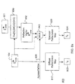
- Figure 1 shows a pipeline 100 that uses an illumination stage 200 according to the invention.
- the input to the pipeline is voxels 102 read from a voxel memory 101, and the output of the pipeline is pixels 108 written to a pixel memory 109.
- the stages of the pipeline 100 interpolate 110 the voxels 102 for a particular point of view to produce samples 103.
- interpolation the neighborhood of a voxel is examined, and values are assigned to sample points along rays.
- re-sampling functions include linear, probabilistic, or nearest neighbor interpolation.
- the samples 103 have their gradients 104 estimated 120. Gradients indicate the direction and magnitude of surface normals.
- the samples 103 are then classified.
- the classified samples are illuminated according to the invention using the estimated gradients 104 in stage 200.
- the illuminated samples 106 are composited 140 to pixel values 108.
- the order of the interpolation, gradient estimation, and classification stages may be different.
- the flow of data in the pipeline of Figure 1 makes it possible to achieve considerable parallelism in a semiconductor or hardware implementation. While one group of data are being read from voxel memory 101, a previously read group is interpolated in the interpolation stages 110, a group read before that is having gradients estimated and being classified in stages 120, etc.
- the pipeline reads a fixed number of voxels in each cycle, and these progress through the pipeline stage-by-stage and cycle-by-cycle. Therefore, even though the number of stages and length of time needed for rendering an individual voxel or sample may be large, many voxels are processed at any one time.
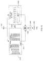
- FIG. 2 shows an illumination stage 200 for a hardware rendering pipeline according to the invention.
- the stage 200 includes three major units, namely gradient magnitude modulation 300, reflectance mapping 800, and lighting 1100.
- the stage 200 also includes four arithmetic logic units (ALUs), i.e., multipliers ( ⁇ ) 201-204, and a multiplexer (MUX) 210.
- ALUs arithmetic logic units
- ⁇ multipliers
- MUX multiplexer
- Each input to the stage 200 comprises an already classified sample 205 from the previous stage, its corresponding gradient vector (G UVW ) 104, and an eye vector (E UVW ) 801 representing the direction from the sample point to the eye of the viewer.
- the sample and its associated gradient vector are received at the rate of one pair per pipeline clock cycle.
- the eye vector is constant throughout the volume. However, in the case of perspective projection, the eye vector must be adjusted for each ray.
- the illumination stage 200 applies specular ( s ), diffuse ( d ) and emissive ( e ) lighting to the classified sample 205 using its associated gradient vector (G UVW ) 104, and other controls described in detail below.
- the illumination stage 200 in pipeline fashion, processes sample and vectors at the rate of one pair per pipeline clock cycle. That is, it comprises a fixed number of processing steps, and data flows through the stage in one direction from beginning to end. There are no loops, feedback, or variation in the number of steps of processing.
- Each of the sub-units of illumination stage 200 is likewise organized in pipeline fashion to accept inputs at the rate of one per cycle and to product outputs at the same rate.
- the gradient vector 104 is provided as input to the modulation unit 300, and the reflectance map unit 800, described below.
- the modulation unit generates four gradient magnitude modulation factors GMOM, GMIM e , GMIM d , and GMIM s .
- GMOM is the factor for opacity modulation, and the other three factors modulate color (RGB) intensities for emissive (e), diffuse (d), and specular (s) lighting, respectively. Modulation can be done in a number of different ways under user control.
- GMOM modulates or attenuates (201) the alpha (opacity) component 206 of the classified sample 205, supplied via the mux 210.
- the mux 210 also receives G UVW in the case that the illumination stage is bypassed altogether.
- GMIM e is multiplied in 202 by k e where k e represents the intensity of the emissive lighting, a constant for the entire volume.
- the modulated k e is denoted by Mk e .
- GMIM d is multiplied in 203 by I d to produce a modulated diffuse intensity MI d .
- GMIM s is multiplied in 204 by I s to produce a specular lighting intensity MI s .
- the values I d and I s are provided via the reflectance mapping unit 800.
- Mk e , MI d , and MI d are inputs to the Lighting unit 1100, as described in Figure 11.
- the main output of the illumination stage 200 is an illuminated sample 106 with Red, Green, Blue color components, and an Alpha components.
- the other two outputs are GmRange Valid 107, and the sign 108 of the dot product of the gradient vector and the eye vector ( G UVW ⁇ E UVW ).
- the value GmRange Valid is the result of comparing the computed gradient magnitude squared against a range defined in a range register. This signal can be used downstream in the compositing stage 140 of the pipeline 100 to further modify the resultant image by selectively including or excluding samples from being composited based upon their gradient magnitude.
- the sign of the dot product indicates whether the gradient is front-facing or back-facing.
- This signal can also be used downstream in the compositing stage to identify a sample as being on a front-facing or back-facing surface. With this information, a simple segmentation of the volume data is possible.
- the output is also clocked at the rate of one illuminated sample pipeline cycle.
- Figure 3 shows the gradient magnitude modulation unit 300 in greater detail.
- the purpose of the unit is to filter gradients using their magnitudes. Filtering accentuate surfaces, and removes noise.
- the unit 300 includes an arithmetic logic unit 310 for taking the dot product of the gradient 104 with itself ( G UVW ⁇ G UVW ), thereby obtaining the square of its magnitude
- the output of the squaring circuit 310 is supplied to a comparator 320 along with range values from a GradientMagnitudeRange register 400 shown in Figure 4.
- the range values include a minimum and maximum valid magnitude.
- the output is also truncated by circuit 330, for example, a shift register, and then supplied to the multiplexer 340 along with
- the output of the mux 340 is used to index a gradient magnitude look-up table (GMLUT) 380, the entries of which are representations of fractional numbers in the range zero to one, inclusive.
- is also provided to a high pass filter (Hi-Pass) filter function 350.
- Hi-Pass high pass filter
- a signal selecting a particular modulation mode is provided on line 360 to a multiplexer 370.
- This signal is derived from a gradient magnitude modulation register (GMM) 500 shown in Figure 5.
- GMM gradient magnitude modulation register
- the parameter values stored in the register 500 as bits can be supplied by the user. Possible modes include various combinations of specular, diffuse, emissive, opacity, high pass diffuse, and high pass specular.
- the GMM 500 includes fields 501-507 stored as 32 bits.
- the various bits control exactly how the user desires to have the modulation performed.
- the grain, base, upper and lower range, and index source field 501-504 are used in conjunction with the GMLUT 380.
- the two high pass fields 505-506 are used by the high pass function 350.
- Field 505 specifies a step value for a high pass filter function.
- Field 506 eliminates either specular or diffuse lighting, or both.
- the values in field 507 select a complex modulation mode for the mux 370 using the magnitude look-up table 380.
- GMOM and GMIM e can have either the GMLUT output or the value 1.0 applied to them based upon the setting of the modulateOpacity and modulateEmissive control bits 0 and 1, in the notation of the C programming language:
- GMIM d and GMIM s can have any of the four following values:
- the unit 300 determines the modulation (attenuation) factors GMOM, GMIM e , GMIM d , and GMIM s 390 according to the selection signal on line 360 and the gradient magnitude of the classified sample 205.
- the modulation factors can be applied to lighting parameters (I d , I s , and k e ) and the opacity of the sample.
- ) of the gradient magnitude is computed in unit 310 by taking the sum of the squares of the components of the gradient vector as follows:
- the gradient vector components are in the range of [-4095, ..., +4095] 24 . Given this range, the range of the computed square of the gradient magnitude is [0, ..., 50,307,075].
- the GmRange Valid signal 107 is set as follows:
- the four modulation factors output by the modulation unit 300 are GMOM, GMIM e , GMIM d , and GMIM s 390. These outputs are in the range of [0.0, ..., 1.0].
- GMOM modulates the opacity (alpha) component of the sample
- GMIM e modulates k e
- GMIM d modulates I d
- diffuse lighting
- GMIM s modulates I s , and thus specular lighting.
- This modulation can be used for a variety of reasons: minimize or eliminate lighting contributions of non-surfaces; minimize or eliminate lighting contributions of samples with low gradients that might exist due to errors in sampling and/or interpolation or noise errors inherent in the volume data set; apply light to only those samples with gradients in a specific range; and include or exclude samples from being composited (GMOM).
- the modulation factor GMOM can, for instance, enable compositing of only homogenous regions by eliminating all surfaces or conversely, enable compositing of only surfaces.
- the unit 300 namely a complex function using a gradient magnitude look-up table (GMLUT) 380, and the step filter function 350.
- GMLUT gradient magnitude look-up table
- the high pass filter function operates on the approximated gradient magnitude.
- This step function produces a high pass modulation factor of either 0.0 or 1.0 to either side of a step value in the gradient magnitude range as defined by the hiPassStart field 505 of the GMM register 500, shown in Figure 5.
- the following equation represents the step function:
- Figure 6 shows an example output 600 for this step function.
- the x-axis depicts the lower-end of the input gradient's magnitude range [0, ..., 255], and the y-axis the magnitude of the high pass output.
- the step value hiPassStart is set to 96.
- the output is 0.0, otherwise, the output is 1.0.
- the GMLUT 380 takes either
- the selection through multiplexer 340 is controlled by the indexSource field 504 of the GMM register.
- the truncated magnitude squared is used if the indexSource signal is true, and the magnitude
- the GMLUT is organized as 128 entries ( entry0 , ..., entry127 ). Each entry is eight bits wide and stores a value in the range [0.0, ..., 1.0].
- the look-up is controlled by the grain, base, upperRangeDefault and lowerRangeDefault fields 501-504 of the GMM register 500. These fields allow the user to specify how the 128 table entries are spread across the table's 13-bit index range.
- the base field 502 specifies where in the index range the first entry ( entry0 ) of the table is indexed.
- the grain field 501 specifies how far apart the table entries are spread starting at the base entry. In other words, the grain is the size of the incremental value between the entries. If the table is programmed to cover less than the 13-bit index range, then the upper-RangeDefault and lowerRangeDefault fields 503-504 specify the GMLUT output value for the uncovered regions above and below, either region can be zero or one.
- Figure 7 shows an example complex attenuation function 700 where the x-axis indicates the gradient index in the range of [0, ..., 4k-1], and the y-axis the GMLUT output value in the range [0.0, ..., 1.0].
- the base is 1536
- the grain is 2.
- Interpolation is performed between the two nearest table entries, and an 8-bit repeating fraction result is produced, again representing the range of [0.0, ..., 1.0].
- the reflectance mapping unit 800 includes a diffuse reflectance map 810, and a specular reflectance map 820.
- the unit also includes a reflectance vector circuit 830 for deriving a reflection vector 802 from an eye vector (E UVW ) 801 and the gradient vector 104 (see also Figures 8b and 10).
- a mux 840 selectively chooses to index the specular reflectance map directly with either the gradient vector or the computed reflection vector 802.
- the inputs to the units are the gradient and eye vectors 104, 801, and the outputs are the diffuse and specular intensities (I d , I s ) 803-804.
- the reflectance mapping unit 800 determines the specular and diffuse intensities (I s and I d ) for each sample 205 based upon its associated gradient vector 104 and the user-specified eye vector (E UVW ) 801. As shown, the diffuse map 810 is indexed by the sample's gradient vector 104, whereas the specular map 820 is typically indexed by either the gradient vector or the computed reflection vector 802 depending on a bypass ( bypassRefVec ) signal 901 shown in Figure 9.
- the maps and the indexing vectors are all specified in unpermuted ( U, V, W ) object space but relative to "physical" or “lighting" space.
- the advantage of this is that the reflectance maps do no have to be recalculated for different view directions.
- gradients estimated from anisotropic or non-orthogonal volume data sets must be corrected to "physical" space for the lighting calculations to work correctly, that is, the same visual appearance will be given, regardless of gantry tilt or scale.
- the specular map 820 may be indexed directly by the gradient vector 104, instead of by the reflection vector 802, by setting a bit in a bypassRefVec field 901 in an Eye Vector register 900 to true as shown in Figure 9.
- the other fields 902-904 of the register 900 respectively store the ( U, V, W ) components of the eye vector.
- Figure 10 shows the relationship between the eye, reflection, and gradient vectors.
- the eye vector 801 is defined to be the vector from the point on a "surface" of the volume 1000 to the eye 1001. Its coordinates are specified in ( U, V, W ) object space by fields 902-904. Note, this vector is normalized to a length of 1.
- the reflection from a light source 1002 to the eye 1001 is dependent upon the gradient vector 104.
- the reflectance vector circuit 830 derives the reflection vector 802 based upon the eye vector 801 specified by the Eye Vector register 900 and the gradient vector 104.
- the gradient vector is not of unit length, i.e., it is unnormalized.
- scaling unit 851, two dot product generators 852, two multipliers 853, and adder 854 the circuit 830 determines an unnormalized reflection vector Ru as:
- each reflectance map is organized as a table with, for example, 1536 entries.
- the entries are spread across the six faces of an imaginary cube in 3D, that is 256 entries on each face.
- Each face includes four quadrants of 64 entries.
- the index to the maps are the unnormalized gradient vector or the reflection vector as selected by the mux 840. Again, magnitude is not important, but direction is.
- the outputs are values, interpolated from four entries of the map, based on the direction of the incoming vector.
- the selection of the face of the cube for access is based on the maximum vector component, and its sign. For instance, if the vector is (75,0,0) in ( u,v,w ) space, then the right face of the cube (positive U) would be chosen. Whereas, if the vector is (-75,0,0), then the left face of the cube is chosen. The quadrant of a face is then selected based upon the sign of the other two vector components.
- a cluster of four neighboring table entries is selected for interpolation to a resultant intensity value.
- This neighborhood is selected by computing two weights that indicate the angle of deflection of the vector from the center of the cube's face to the outer edges of the face. Given that there are a power-of-two entries in each direction of a face's quadrant and the vector's components are represented by a power-of-two value, these weights can easily be derived by simple bit extraction of the vector's components.
- Figure 11 shows the lighting unit 1100 in greater detail.
- the unit comprises a number of arithmetic logic units (ALUs) that add ( ⁇ ) and multiply ( ⁇ ) signals derived by the modulation and mapping units, and clamps.
- the lighting unit 1100 applies the diffuse and specular lighting coefficients, k d and k s , the modulated emissive, diffuse, and specular intensities (Mk e , MI d , MI s ), and the specular color (R s , G s , B s ) 1101 to the classified RGBa sample 205.
- ALUs arithmetic logic units
- is derived from a square root approximation of
- the approximation is based on a Newton-Raphson approximation. Generally, Newton's method involves numerous iterations to find the square-root of an input number. Recall from above the input is:
- the Newton-Raphson method is an iterative algorithm, based on tangents and their midpoints along a specified curve, in this case, the square root curve.
- the method works as follows:
- Figure 12 graphically shows how the Newton-Raphson method for an example number 163.
- the x-axis indicates the input number, and the y-axis the square root.
- the curve 1200 plots the square root function.
- the input number (163 is located between the two power-of-two numbers: 128 (2 7 ) and 256 (2 8 ).
- the computed square root of the lower bound (128) is chosen for the first guess. This is 11.3137.
- the division result, dividing the input number (163) by the guessed answer 11.3137 yields 14.4073. This results in an error of 3.093 (14.4073-11.3137).
- the next guess is computed as follows:
- this method uses both division and iteration. Division is extremely expensive in circuitry, and iteration inconsistent with a pipelined architecture. The multiplication by 1/2 can be accomplished by a simple shift right of the binary number. There are also a subtraction and possible complement, e.g., another adder, and an addition required for each iteration.
- the Synopsys company offers a square root circuit (DW02_sqrt: Combinatorial Square Root) in their Design Ware library based on Newton-Raphson, see “www.synopsys.com.” These are non-pipelined devices of which there are two variants with the following typical characteristics: either 300 ns and 9000 gates, or 600 ns and 1100 gates based on a cycle time of approximately 10 nanoseconds. These, of course, reuse the same divider, adder, and subtraction circuits for each of 30-60 iterations, precluding pipeline operation.
- DW02_sqrt Combinatorial Square Root
- a preferred implementation is based on Newton-Raphson's method but varies significantly in that it is pipelined.
- the present implementation employs only one iteration and assumes predefined estimates of the square root at predefined points along the curve 1200 and tangents with pre-defined "slopes" connected, end-to-end, to approximate the square root function.
- predefined estimates of the square root at predefined points along the curve 1200 and tangents with pre-defined "slopes" connected, end-to-end, to approximate the square root function.
- division and multiplication are not used, and all computations are merely shifts and adds.
- the invention takes advantage of the fact the square root of a number expressed as a power-of-two ( 2 n ) is 2 n/2 . So, a first approximation is made by a simple range determination. For a given input find a nearest power-of-two number, and use its square root as the first guess. Now, if the range check is done for odd powers-of-two (i.e., in 2 n , n is odd), the first approximation will be in the middle of a range reducing the largest possible error by half.
- Figure 13 is a block diagram of a preferred implementation of a square root approximation unit 1300.
- the unit includes a combinatorial logic block 1310 labeled “Select Range & Guess,” another block of combinatorial logic 1320 labeled “Divide Input by Guess,” an adder 1330, and a shifter 1340.
- the unit 1300 takes a number (for example,
- the block 1310 determines guess 1311 and shift 1312.
- the value guess is the nearest square root, expressed as a power-of-two number, of a largest odd power-of-two number less than or equal to input .
- This range test can be as a simple bit test operation. The range test can begin at 32,768 (hex 0x8000 or 2 15 ) which has a nearest square root of 256 (2 8 ). In other words, because n is odd, the root is "guessed” as 2 (n + 1)/2 . The corresponding initial guess is 256, and shift is 8.
- Block 1320 divides input by guess . Because guess is a power-of-two, the divide can be done as simple shift operation.
- the adder 1330 adds guess to the result of input /guess ,
- the shifter 1340 implements the final divide by two:
- the divide is simplified to a shift of the input .
- the guess is added to the result of dividing the input by the guess by the adder 1340.
- the sum is then divided by two in the shifter 1340 to give a close approximation of the square root of the input.
- Figure 14 is a graph 1400 comparing the exact gradient magnitude 1401 with the approximate gradient 1402, and the error in the approximation 1403.
- This circuit requires a very small number of gates to implement. Additionally, it the circuit is well suited to a pipelined design as the logic may be spread over as many pipe stages as desired without having to replicate any logic because no loops or iterations are involved.
- An actual implementation of the circuit 1300 takes 850 gates and has a propagation delay of 5 nanoseconds, compared with 300 Ns and 9000 gates from above.
- the method can be improved to provide a better approximation without increasing the number of iterations, but rather by piecewise linear approximation of the square-root function that involves division by a fixed set of numbers that are not powers of two.
- the set of numbers is chosen so that division is can still be accomplished by a small number of shifts and adds in a fixed number of steps.
- the effect is to decrease the size of the ranges for the first guess by doubling the number of points at which first " guess " is taken of the square root of the input . This reduces the maximum error shown in Figure 14 in this modified single-step approximation of the square root.
- the starting point is selected from a range including the input number, and the sloped" tangent to be applied from that point to the next range.
Landscapes
- Physics & Mathematics (AREA)
- General Physics & Mathematics (AREA)
- Engineering & Computer Science (AREA)
- Theoretical Computer Science (AREA)
- Image Generation (AREA)
- Image Processing (AREA)
- Complex Calculations (AREA)
Applications Claiming Priority (2)
| Application Number | Priority Date | Filing Date | Title |
|---|---|---|---|
| US09/315,238 US6369816B1 (en) | 1998-11-12 | 1999-05-20 | Method for modulating volume samples using gradient magnitudes and complex functions over a range of values |
| US315238 | 1999-05-20 |
Publications (2)
| Publication Number | Publication Date |
|---|---|
| EP1054349A2 true EP1054349A2 (de) | 2000-11-22 |
| EP1054349A3 EP1054349A3 (de) | 2003-05-28 |
Family
ID=23223504
Family Applications (1)
| Application Number | Title | Priority Date | Filing Date |
|---|---|---|---|
| EP00110609A Withdrawn EP1054349A3 (de) | 1999-05-20 | 2000-05-18 | Verfahren zum Moduleiren von Volumiger Proben in einer Bilddarstellung-Pipeline-Struktur |
Country Status (3)
| Country | Link |
|---|---|
| US (1) | US6369816B1 (de) |
| EP (1) | EP1054349A3 (de) |
| JP (1) | JP2001005995A (de) |
Cited By (2)
| Publication number | Priority date | Publication date | Assignee | Title |
|---|---|---|---|---|
| WO2004047028A1 (de) * | 2002-11-15 | 2004-06-03 | Siemens Aktiengesellschaft | Verfahren zur darstellung eines in einem volumendatensatz abgebildeten objektes |
| USRE42952E1 (en) | 1999-11-05 | 2011-11-22 | Vital Images, Inc. | Teleradiology systems for rendering and visualizing remotely-located volume data sets |
Families Citing this family (20)
| Publication number | Priority date | Publication date | Assignee | Title |
|---|---|---|---|---|
| DE19835215C2 (de) * | 1998-08-05 | 2000-07-27 | Mannesmann Vdo Ag | Kombinationsinstrument |
| US6914602B2 (en) * | 2001-01-19 | 2005-07-05 | Adobe Systems Incorporated | Approximating gradients with offset midpoints |
| US7039723B2 (en) * | 2001-08-31 | 2006-05-02 | Hinnovation, Inc. | On-line image processing and communication system |
| US20030086595A1 (en) * | 2001-11-07 | 2003-05-08 | Hui Hu | Display parameter-dependent pre-transmission processing of image data |
| JP3836097B2 (ja) * | 2003-09-19 | 2006-10-18 | ザイオソフト株式会社 | 医用画像生成装置および方法、ならびに、プログラム |
| US20050143654A1 (en) * | 2003-11-29 | 2005-06-30 | Karel Zuiderveld | Systems and methods for segmented volume rendering using a programmable graphics pipeline |
| US7660488B2 (en) | 2004-11-04 | 2010-02-09 | Dr Systems, Inc. | Systems and methods for viewing medical images |
| US7920152B2 (en) | 2004-11-04 | 2011-04-05 | Dr Systems, Inc. | Systems and methods for viewing medical 3D imaging volumes |
| US7885440B2 (en) | 2004-11-04 | 2011-02-08 | Dr Systems, Inc. | Systems and methods for interleaving series of medical images |
| US7787672B2 (en) | 2004-11-04 | 2010-08-31 | Dr Systems, Inc. | Systems and methods for matching, naming, and displaying medical images |
| US7970625B2 (en) | 2004-11-04 | 2011-06-28 | Dr Systems, Inc. | Systems and methods for retrieval of medical data |
| US7953614B1 (en) | 2006-11-22 | 2011-05-31 | Dr Systems, Inc. | Smart placement rules |
| US20080232694A1 (en) * | 2007-03-21 | 2008-09-25 | Peter Sulatycke | Fast imaging data classification method and apparatus |
| DE102007027738B4 (de) | 2007-06-15 | 2009-07-09 | Siemens Ag | Verfahren und Vorrichtung zur Visualisierung eines tomographischen Volumendatensatzes unter Nutzung der Gradientenmagnitude |
| US8380533B2 (en) | 2008-11-19 | 2013-02-19 | DR Systems Inc. | System and method of providing dynamic and customizable medical examination forms |
| US8712120B1 (en) | 2009-09-28 | 2014-04-29 | Dr Systems, Inc. | Rules-based approach to transferring and/or viewing medical images |
| US20110125016A1 (en) * | 2009-11-25 | 2011-05-26 | Siemens Medical Solutions Usa, Inc. | Fetal rendering in medical diagnostic ultrasound |
| US9075899B1 (en) | 2011-08-11 | 2015-07-07 | D.R. Systems, Inc. | Automated display settings for categories of items |
| US9495604B1 (en) | 2013-01-09 | 2016-11-15 | D.R. Systems, Inc. | Intelligent management of computerized advanced processing |
| US10929508B2 (en) | 2015-04-30 | 2021-02-23 | Merge Healthcare Solutions Inc. | Database systems and interactive user interfaces for dynamic interaction with, and indications of, digital medical image data |
Citations (1)
| Publication number | Priority date | Publication date | Assignee | Title |
|---|---|---|---|---|
| EP1054359A2 (de) * | 1999-05-20 | 2000-11-22 | Mitsubishi Denki Kabushiki Kaisha | Verfahren und vorrichtung zum modelieren der Beleuchtung in einer Bilderstellung-Pipeline-Struktur |
Family Cites Families (11)
| Publication number | Priority date | Publication date | Assignee | Title |
|---|---|---|---|---|
| CA1258923A (en) | 1986-04-14 | 1989-08-29 | Robert A. Drebin | Methods and apparatus for imaging volume data |
| US5201035A (en) | 1990-07-09 | 1993-04-06 | The United States Of America As Represented By The Secretary Of The Air Force | Dynamic algorithm selection for volume rendering, isocontour and body extraction within a multiple-instruction, multiple-data multiprocessor |
| EP0739513B1 (de) | 1991-08-13 | 1999-10-27 | The Board Of Regents Of The University Of Washington | Verfahren zur übertragung von daten |
| US5644689A (en) | 1992-01-13 | 1997-07-01 | Hitachi, Ltd. | Arbitrary viewpoint three-dimensional imaging method using compressed voxel data constructed by a directed search of voxel data representing an image of an object and an arbitrary viewpoint |
| US5377313A (en) * | 1992-01-29 | 1994-12-27 | International Business Machines Corporation | Computer graphics display method and system with shadow generation |
| IL109462A0 (en) * | 1993-04-30 | 1994-07-31 | Scitex Corp Ltd | Method for generating artificial shadow |
| US5422986A (en) * | 1993-05-12 | 1995-06-06 | Pacific Data Images, Inc. | Method for generating soft-edge mattes for visual elements of images |
| US5594842A (en) | 1994-09-06 | 1997-01-14 | The Research Foundation Of State University Of New York | Apparatus and method for real-time volume visualization |
| US5561752A (en) * | 1994-12-22 | 1996-10-01 | Apple Computer, Inc. | Multipass graphics rendering method and apparatus with re-traverse flag |
| US5760786A (en) * | 1995-12-27 | 1998-06-02 | Mitsubishi Electric Information Technology Center America, Inc. | Simultaneous constructive solid geometry (CSG) modeling for multiple objects |
| US5739819A (en) * | 1996-02-05 | 1998-04-14 | Scitex Corporation Ltd. | Method and apparatus for generating an artificial shadow in a two dimensional color image |
-
1999
- 1999-05-20 US US09/315,238 patent/US6369816B1/en not_active Expired - Lifetime
-
2000
- 2000-05-18 EP EP00110609A patent/EP1054349A3/de not_active Withdrawn
- 2000-05-19 JP JP2000148879A patent/JP2001005995A/ja not_active Abandoned
Patent Citations (1)
| Publication number | Priority date | Publication date | Assignee | Title |
|---|---|---|---|---|
| EP1054359A2 (de) * | 1999-05-20 | 2000-11-22 | Mitsubishi Denki Kabushiki Kaisha | Verfahren und vorrichtung zum modelieren der Beleuchtung in einer Bilderstellung-Pipeline-Struktur |
Non-Patent Citations (1)
| Title |
|---|
| PFISTER HANSPETER ET AL: "VolumePro real-time ray-casting system" PROCEEDINGS OF THE 1999 ANNUAL CONFERENCE - SIGGRAPH 99;LOS ANGELES, CA, USA AUG 8-AUG 13 1999, 1999, pages 251-260, XP002235465 Proc ACM SIGGRAPH Conf Computer Graph;Proceedings of the ACM SIGGRAPH Conference on Computer Graphics 1999 ACM, New York, NY, USA * |
Cited By (5)
| Publication number | Priority date | Publication date | Assignee | Title |
|---|---|---|---|---|
| USRE42952E1 (en) | 1999-11-05 | 2011-11-22 | Vital Images, Inc. | Teleradiology systems for rendering and visualizing remotely-located volume data sets |
| USRE44336E1 (en) | 1999-11-05 | 2013-07-02 | Vital Images, Inc. | Teleradiology systems for rendering and visualizing remotely-located volume data sets |
| WO2004047028A1 (de) * | 2002-11-15 | 2004-06-03 | Siemens Aktiengesellschaft | Verfahren zur darstellung eines in einem volumendatensatz abgebildeten objektes |
| DE10253617B4 (de) * | 2002-11-15 | 2005-06-30 | Siemens Ag | Verfahren zur Darstellung eines ineinem Volumendatensatz abgebildeten Objektes |
| US7457816B2 (en) | 2002-11-15 | 2008-11-25 | Siemens Aktiengesellschaft | Method for depicting an object displayed in a volume data set |
Also Published As
| Publication number | Publication date |
|---|---|
| EP1054349A3 (de) | 2003-05-28 |
| JP2001005995A (ja) | 2001-01-12 |
| US6369816B1 (en) | 2002-04-09 |
Similar Documents
| Publication | Publication Date | Title |
|---|---|---|
| US6342885B1 (en) | Method and apparatus for illuminating volume data in a rendering pipeline | |
| US6356265B1 (en) | Method and apparatus for modulating lighting with gradient magnitudes of volume data in a rendering pipeline | |
| US6426749B1 (en) | Method and apparatus for mapping reflectance while illuminating volume data in a rendering pipeline | |
| US6369816B1 (en) | Method for modulating volume samples using gradient magnitudes and complex functions over a range of values | |
| US6404429B1 (en) | Method for modulating volume samples with gradient magnitude vectors and step functions | |
| US6411296B1 (en) | Method and apparatus for applying modulated lighting to volume data in a rendering pipeline | |
| US6628290B1 (en) | Graphics pipeline selectively providing multiple pixels or multiple textures | |
| US6333744B1 (en) | Graphics pipeline including combiner stages | |
| US7362328B2 (en) | Interface and method of interfacing between a parametric modelling unit and a polygon based rendering system | |
| Everitt | Interactive order-independent transparency | |
| US6483507B2 (en) | Super-sampling and gradient estimation in a ray-casting volume rendering system | |
| EP1183653A1 (de) | Verfahren zur perspektivischen darstellung, ausgehend von einem voxelraum | |
| van Scheltinga et al. | Design of an on-chip reflectance map | |
| EP1054358A2 (de) | Verfahren und Gerät zur Funktionannäherung | |
| US6191788B1 (en) | Method and apparatus for approximating nonlinear functions in a graphics system | |
| Matsumura et al. | Accelerated isosurface polygonization for dynamic volume data using programmable graphics hardware | |
| Feda et al. | A median cut algorithm for efficient sampling of radiosity functions | |
| EP1209618A1 (de) | Pipeline-Volumendarstellung | |
| Knittel | A compact shader for FPGA-based volume rendering accelerators | |
| Morén | Efficient volume rendering on the face centered and body centered cubic grids | |
| Parilov et al. | Per-pixel divisions | |
| Szántó et al. | Implementing a Programmable Pixel Pipeline in FPGAs |
Legal Events
| Date | Code | Title | Description |
|---|---|---|---|
| PUAI | Public reference made under article 153(3) epc to a published international application that has entered the european phase |
Free format text: ORIGINAL CODE: 0009012 |
|
| AK | Designated contracting states |
Kind code of ref document: A2 Designated state(s): AT BE CH CY DE DK ES FI FR GB GR IE IT LI LU MC NL PT SE |
|
| AX | Request for extension of the european patent |
Free format text: AL;LT;LV;MK;RO;SI |
|
| RAP1 | Party data changed (applicant data changed or rights of an application transferred) |
Owner name: TERARECON, INC., A DELAWARE CORPORATION |
|
| PUAL | Search report despatched |
Free format text: ORIGINAL CODE: 0009013 |
|
| RIC1 | Information provided on ipc code assigned before grant |
Ipc: 7G 06T 1/20 B Ipc: 7G 06T 15/50 A |
|
| AK | Designated contracting states |
Designated state(s): AT BE CH CY DE DK ES FI FR GB GR IE IT LI LU MC NL PT SE |
|
| AX | Request for extension of the european patent |
Extension state: AL LT LV MK RO SI |
|
| STAA | Information on the status of an ep patent application or granted ep patent |
Free format text: STATUS: THE APPLICATION IS DEEMED TO BE WITHDRAWN |
|
| 18D | Application deemed to be withdrawn |
Effective date: 20020619 |