EP1054247A2 - Apparatus for determining geometrical defects in a motor vehicle wheel (wheel rim + tyre) mounted on a tyre removal machine, and the tyre removal machine equipped therewith - Google Patents
Apparatus for determining geometrical defects in a motor vehicle wheel (wheel rim + tyre) mounted on a tyre removal machine, and the tyre removal machine equipped therewith Download PDFInfo
- Publication number
- EP1054247A2 EP1054247A2 EP00201415A EP00201415A EP1054247A2 EP 1054247 A2 EP1054247 A2 EP 1054247A2 EP 00201415 A EP00201415 A EP 00201415A EP 00201415 A EP00201415 A EP 00201415A EP 1054247 A2 EP1054247 A2 EP 1054247A2
- Authority
- EP
- European Patent Office
- Prior art keywords
- tyre
- self
- wheel
- centering unit
- wheel rim
- Prior art date
- Legal status (The legal status is an assumption and is not a legal conclusion. Google has not performed a legal analysis and makes no representation as to the accuracy of the status listed.)
- Withdrawn
Links
- 230000007547 defect Effects 0.000 title claims abstract description 11
- 238000005259 measurement Methods 0.000 claims abstract description 25
- 239000011324 bead Substances 0.000 claims abstract description 9
- 238000013480 data collection Methods 0.000 claims description 4
- 230000010355 oscillation Effects 0.000 claims description 3
- 230000014759 maintenance of location Effects 0.000 claims 2
- 239000000470 constituent Substances 0.000 claims 1
- 230000000694 effects Effects 0.000 description 2
- 230000001788 irregular Effects 0.000 description 2
- 238000004519 manufacturing process Methods 0.000 description 2
- 238000010276 construction Methods 0.000 description 1
- 230000002596 correlated effect Effects 0.000 description 1
- 230000003247 decreasing effect Effects 0.000 description 1
- 238000000034 method Methods 0.000 description 1
- 230000001151 other effect Effects 0.000 description 1
- 238000005096 rolling process Methods 0.000 description 1
- 238000012795 verification Methods 0.000 description 1
Images


Classifications
-
- G—PHYSICS
- G01—MEASURING; TESTING
- G01M—TESTING STATIC OR DYNAMIC BALANCE OF MACHINES OR STRUCTURES; TESTING OF STRUCTURES OR APPARATUS, NOT OTHERWISE PROVIDED FOR
- G01M17/00—Testing of vehicles
- G01M17/007—Wheeled or endless-tracked vehicles
- G01M17/02—Tyres
- G01M17/022—Tyres the tyre co-operating with rotatable rolls
-
- B—PERFORMING OPERATIONS; TRANSPORTING
- B60—VEHICLES IN GENERAL
- B60C—VEHICLE TYRES; TYRE INFLATION; TYRE CHANGING; CONNECTING VALVES TO INFLATABLE ELASTIC BODIES IN GENERAL; DEVICES OR ARRANGEMENTS RELATED TO TYRES
- B60C25/00—Apparatus or tools adapted for mounting, removing or inspecting tyres
- B60C25/002—Inspecting tyres
Definitions
- This invention relates generally to the balancing of a motor vehicle wheel (wheel rim + tyre), and in particular to an apparatus able to directly determine any shape imperfections in said wheel when this is positioned on the self-centering unit of a tyre removal machine.
- the wheel rim plus tyre part of a vehicle wheel can present various shape imperfections or defects which can disturb vehicle travel during wheel rotation.
- the most common imperfections or defects include the following: ovalized wheel rim shape; conical wheel rim shape due to slight diameter differences in the bead retaining flanges; ovalized tyre shape; and conical tyre tread shape.
- the same tyre can also have irregular rigidity (or deformability), due to the position and nature of the joints between its inner bands.
- the main object of this invention is to provide an apparatus able to determine said imperfections or defects when said wheel is positioned on the self-centering unit of a tyre removal machine, so that account can be taken thereof on removing and remounting the tyre.
- the apparatus of the invention comprises at least one measurement unit to be associated with the self-centering unit of a tyre removal machine, in order to occupy a rest position in which it lies outside the operational region of said self-centering unit and a working position in which it can assume a first measuring configuration in which it is in light contact with the bead retaining flange of the wheel rim of that wheel at that moment mounted on the moving self-centering unit, and a second configuration in which it is in light contact with the tread of the tyre of said mounted wheel, said measurement unit being connected to a system for collecting and displaying the data obtained.
- said at least one measurement unit When said at least one measurement unit, described in detail hereinafter, it measures any wheel rim ovalization, whereas when in said second measuring configuration it measures any ovalization of the tyre tread.
- said at least one measurement unit is also equipped with means which, simultaneously with said measurement of any wheel rim and tread ovalization, also measure any conicity thereof.
- Two measurement units are preferably provided, of which one effects said wheel rim measurements and the other effects the same measurements on the tyre tread.
- a further measurement unit can be provided to determine any tyre flexibility or deformability irregularities.
- Goniometer means are preferably associated with said measurement units in order to provide strict correlation between the error data determined by the measurement units and the respective angular positions.
- the apparatus is preferably mounted on a structure which is to be located to the rear of the vertical-axis self-centering unit of a tyre removal machine and has a vertical plane of symmetry containing said vertical axis.
- FIGS. 1 and 2 show a profiled structure 33 comprising a horizontal square base 1 provided with adjustable support feet 3 and having a portal 2 extending upwards from a marginal flange thereof.
- Said base 1 and portal 2 comprise four holed lugs 4 or other equivalent members, by which the structure 33 can be connected to the body of a tyre removal machine with a self-centering unit of vertical axis, for example of the type shown partially in Figure 3.
- Said structure 33 is intended to be connected to said tyre removal machine such that the vertical plane of symmetry 200 (see Figure 2) of the portal 2 contains the vertical axis 100 of said self-centering unit.
- a fixed horizontal plate 22 and a first 44 and second 55 horizontal shaft are provided, from the bottom upwards, a fixed horizontal plate 22 and a first 44 and second 55 horizontal shaft, these latter being rotatably supported by said uprights by way of suitable friction bushes.
- latches operated by small cylinder-piston units can be provided.
- two side-by-side idle cylindrical rollers of vertical axis can be provided, controlled by the same cylinder-piston unit.
- said idle rollers 6 have a vertical dimension at least equal to the maximum width of the tread 77 of the tyre 7.
- the roller 6 must act along a horizontal direction representing a radius of the self-centering unit of the tyre removal machine, which in Figures 3 and 4 is indicated by 128, its jaws being indicated by 129 (see also Figure 2).
- transducer 130 arranged to measure the small movements to which this rod is subjected while examining a vehicle wheel, which is rotated by the self-centering unit 128.
- the roller 6 is maintained urged against the tread 77 with a relatively high force, from 200 to 400 kg, so that any discontinuities in the flexibility or elasticity of the tyre carcass can be determined.
- An indicator device is also provided to indicate when the data read by the sensing means of the invention attain maximum (or minimum) values, to enable said values to be correlated with the specific angular positions both of the tyre 7 and of the wheel rim 70.
- the two ends of the lower shaft 44 extend beyond the uprights of the portal 2 where they carry two hollow arms 8 hinged on respective pins indicated by 88.
- Said pins have a threaded end, namely the rear end in Figure 2, on which there is screwed a ring from which a lever 9 branches.
- each hollow arm 8 there is hinged at 10 an arched appendix 22 having its concavity facing the plane 200, with said hinge 10 there being associated a potentiometer 110 (see Figure 2) arranged to determine oscillations of the appendix 11 about the arm 8.
- each appendix 11 supports a U-piece carrying a respective idle cylindrical roller 12 which when in the working configuration (see Figures 2 and 4) lies with its axis virtually vertical.
- said roller 12 When in said working configuration, said roller 12 is arranged such that its outer cylindrical surface rolls along the central band of the tyre tread 77 (see Figure 3).
- roller 12 presses against said central band with a relatively small force, of the order of 0.4-0.8 kg.
- said positioning is effected manually, however there is nothing to prevent this positioning from being effected automatically, as will be apparent to an expert of the art.
- roller 6 the automatic positioning of said means being controlled by the data collection and display system with which the machine is supplied and which comprises an externally accessible memory for inserting characteristic data of currently available wheels (wheel rim + tyre).
- said data collection system is indicated schematically by 888, the respective display devices being indicated by 777.
- each appendix 11 to which the respective roller-carrying U-piece is fixed is shaped as a relatively thin plate, on which a strain gauge 444 or better a strain gauge bridge is cemented.
- said plate portion lies substantially horizontally (see Figures 2, 4).
- the two rollers 12 make contact with the tread 77 at two substantially diametrically opposite points, the potentiometers 110 sensing any circularity defects of the tread 77, and the strain gauges 444 determining any tread conicity.
- these are substantially identical to those associated with the underlying shaft 44, and comprise: a hinge pin 881; a control lever 91; a hollow arm 81; an arched appendix 111 hinged on the axis 101 to said hollow arm 81; a potentiometer 1101 (or equivalent); a roller 121; and a strain gauge (or strain gauge bridge) 4441.
- the arched appendix 111 has its concavity facing the self-centering unit to enable the respective roller 121 to be easily inserted into the hollow of the wheel rim 70 and rest against the ring portion 700 lying internal to the respective bead retaining flange 701.
- rollers 12 In the same manner as the rollers 12, during data measurement the rollers 121 rest (with a force of the order of 0.4-0.8 kg) against two substantially diametrically opposite points of said ring portion 700, with the potentiometer 1101 sensing any defects in the roundness of the wheel rim 70, and the strain gauge (or strain gauge bridge) 444 determining any tread conicity.
- the aforedescribed data acquiring units are preferably activated simultaneously, ie they are arranged as shown in Figure 2, then to obtain data from the wheel mounted on the self-centering unit this latter is activated, after which the acquired data appear on the display 777.
- the said units can also be used only in part, or even individually, for example if only the wheel 70 is mounted on the self-centering unit.
- the rollers 12 are preferably arranged in contact with the outer circumferential edge 701 of the bead retaining flange as this mode of verification is known to be normally more precise than that achieved with the rollers 12 in contact with the inner ring portion 700 of the bead retaining flange.
- the embodiment illustrated is the most complete, however the apparatus could comprise only two measurement units, associated with the central roller 6 and the pair of opposite rollers 12, or even with the two rollers 12 alone.
- the supports for the rollers 12 must be modified to enable them to act both on the inside of the wheel rim 70, and on the outside of the wheel rim and tyre 7.
- the operator mounts the tyre on the wheel rim such that the major axes of said oval shapes are mutually perpendicular.
- the axis assumed for its oval shape is a false axis rotated about said major axis towards the side on which said weaker point lies.
- the tread and wheel rim are both conical in shape, with the minor base situated on the same side, the tyre is inverted from the position which it had during the examination.
- measuring devices instead of the specifically mentioned measuring devices, other measuring devices can be provided, for example force measurers, pressure measurers (typically for the cylinder-piston unit 5) or torque measurers.
- roller 6 and the pairs of rollers 12 and 121 can also operate differently from that described, in that the roller 6 does not necessarily have to act in the wheel radial direction, and the pairs of rollers 12 and 121 do not necessarily have to be positioned diametrically opposite each other on the wheel.
- rollers can be arranged differently, with any positions different from those already defined being fed into the data collection and display system 888 for appropriate computation.
Landscapes
- Physics & Mathematics (AREA)
- General Physics & Mathematics (AREA)
- Engineering & Computer Science (AREA)
- Mechanical Engineering (AREA)
- Testing Of Balance (AREA)
- Length Measuring Devices With Unspecified Measuring Means (AREA)
- Length Measuring Devices By Optical Means (AREA)
Abstract
Description
- This invention relates generally to the balancing of a motor vehicle wheel (wheel rim + tyre), and in particular to an apparatus able to directly determine any shape imperfections in said wheel when this is positioned on the self-centering unit of a tyre removal machine.
- The wheel rim plus tyre part of a vehicle wheel can present various shape imperfections or defects which can disturb vehicle travel during wheel rotation.
- The most common imperfections or defects include the following: ovalized wheel rim shape; conical wheel rim shape due to slight diameter differences in the bead retaining flanges; ovalized tyre shape; and conical tyre tread shape.
- The same tyre can also have irregular rigidity (or deformability), due to the position and nature of the joints between its inner bands.
- Said defects or imperfections lead to irregular tyre rolling, so disturbing vehicle travel and decreasing travelling comfort.
- The negative effects of the aforesaid shape defects, if present in both the tyre and wheel rim, can often be greatly reduced or even totally eliminated by suitably positioning the tyre relative to the wheel rim, in order to compensate the defects.
- The main object of this invention is to provide an apparatus able to determine said imperfections or defects when said wheel is positioned on the self-centering unit of a tyre removal machine, so that account can be taken thereof on removing and remounting the tyre.
- Said object is attained within the framework of a constructionally simple, reliable and low-cost solution usable on existing tyre removal machines in general and on tyre removal machines of new construction, by virtue of an apparatus having the characteristics defined in claims 1 to 11.
- The apparatus of the invention comprises at least one measurement unit to be associated with the self-centering unit of a tyre removal machine, in order to occupy a rest position in which it lies outside the operational region of said self-centering unit and a working position in which it can assume a first measuring configuration in which it is in light contact with the bead retaining flange of the wheel rim of that wheel at that moment mounted on the moving self-centering unit, and a second configuration in which it is in light contact with the tread of the tyre of said mounted wheel, said measurement unit being connected to a system for collecting and displaying the data obtained.
- When said at least one measurement unit, described in detail hereinafter, is in said first measuring configuration, it measures any wheel rim ovalization, whereas when in said second measuring configuration it measures any ovalization of the tyre tread.
- According to a preferred embodiment, said at least one measurement unit is also equipped with means which, simultaneously with said measurement of any wheel rim and tread ovalization, also measure any conicity thereof.
- Two measurement units are preferably provided, of which one effects said wheel rim measurements and the other effects the same measurements on the tyre tread.
- A further measurement unit can be provided to determine any tyre flexibility or deformability irregularities.
- Goniometer means, also suitably connected to said collection and display system, are preferably associated with said measurement units in order to provide strict correlation between the error data determined by the measurement units and the respective angular positions.
- The apparatus is preferably mounted on a structure which is to be located to the rear of the vertical-axis self-centering unit of a tyre removal machine and has a vertical plane of symmetry containing said vertical axis.
- The constructional characteristics and merits of the invention will be apparent from the ensuing detailed description given with reference to the figures of the accompanying drawings, which show a preferred embodiment thereof by way of non-limiting example.
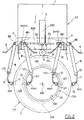
- Figure 1 is a perspective view showing the most equipped version of the apparatus of the invention, to be associated with an existing tyre removal machine, the three respective measurement units being shown in their rest configuration.
- Figure 2 is a plan view of the preceding figure, with the measurement units shown in their working configuration.
- Figure 3 is a partial perspective view showing a tyre removal machine already provided with the apparatus of the invention on manufacture.
- Figure 4 is a partial perspective view with parts cut away to show how the means of the invention operate on a vehicle wheel.
-
- Said figures, and in particular Figures 1 and 2, show a profiled
structure 33 comprising a horizontal square base 1 provided withadjustable support feet 3 and having aportal 2 extending upwards from a marginal flange thereof. - Said base 1 and
portal 2 comprise fourholed lugs 4 or other equivalent members, by which thestructure 33 can be connected to the body of a tyre removal machine with a self-centering unit of vertical axis, for example of the type shown partially in Figure 3. - Said
structure 33 is intended to be connected to said tyre removal machine such that the the vertical plane of symmetry 200 (see Figure 2) of theportal 2 contains thevertical axis 100 of said self-centering unit. - Between the uprights of the
portal 2 there are provided, from the bottom upwards, a fixedhorizontal plate 22 and a first 44 and second 55 horizontal shaft, these latter being rotatably supported by said uprights by way of suitable friction bushes. - Instead of said bushes, latches operated by small cylinder-piston units can be provided.
- To that side of the
plate 22 facing the base 1 there is centrally fixed a cylinder-piston unit 5, the rod of which passes throughsaid plate 22, beyond which it supports an idlecylindrical roller 6 of vertical axis. - Alternatively, instead of said
idle roller 6, two side-by-side idle cylindrical rollers of vertical axis can be provided, controlled by the same cylinder-piston unit. - In either case, it is important that said
idle rollers 6 have a vertical dimension at least equal to the maximum width of thetread 77 of thetyre 7. - It is also important for the longitudinal axis of the cylinder-
piston unit 5 and the axis of theroller 6 to lie insaid plane 200 of symmetry. - The
roller 6 must act along a horizontal direction representing a radius of the self-centering unit of the tyre removal machine, which in Figures 3 and 4 is indicated by 128, its jaws being indicated by 129 (see also Figure 2). - With the rod of said cylinder-
piston unit 5 there is associated atransducer 130 arranged to measure the small movements to which this rod is subjected while examining a vehicle wheel, which is rotated by the self-centering unit 128. - During said examination the
roller 6 is maintained urged against thetread 77 with a relatively high force, from 200 to 400 kg, so that any discontinuities in the flexibility or elasticity of the tyre carcass can be determined. - An indicator device, indicated by 131 in Figure 1, is also provided to indicate when the data read by the sensing means of the invention attain maximum (or minimum) values, to enable said values to be correlated with the specific angular positions both of the
tyre 7 and of thewheel rim 70. - As can be seen, the two ends of the
lower shaft 44 extend beyond the uprights of theportal 2 where they carry twohollow arms 8 hinged on respective pins indicated by 88. - Said pins have a threaded end, namely the rear end in Figure 2, on which there is screwed a ring from which a
lever 9 branches. - This has two functions, namely to rotate the
hollow arms 8 about the axis of theshaft 44, and to lock and release the rotation of the respectivehollow arm 8 about itspin 88. - To the other end of each
hollow arm 8 there is hinged at 10 anarched appendix 22 having its concavity facing theplane 200, with saidhinge 10 there being associated a potentiometer 110 (see Figure 2) arranged to determine oscillations of theappendix 11 about thearm 8. - The free end of each
appendix 11 supports a U-piece carrying a respective idlecylindrical roller 12 which when in the working configuration (see Figures 2 and 4) lies with its axis virtually vertical. - When in said working configuration, said
roller 12 is arranged such that its outer cylindrical surface rolls along the central band of the tyre tread 77 (see Figure 3). - At the moment in which it becomes positioned in said working configuration the
roller 12 presses against said central band with a relatively small force, of the order of 0.4-0.8 kg. - As stated heretofore, said positioning is effected manually, however there is nothing to prevent this positioning from being effected automatically, as will be apparent to an expert of the art.
- The same considerations apply to the
roller 6, the automatic positioning of said means being controlled by the data collection and display system with which the machine is supplied and which comprises an externally accessible memory for inserting characteristic data of currently available wheels (wheel rim + tyre). - In Figures 1 to 3, said data collection system is indicated schematically by 888, the respective display devices being indicated by 777.
- That end portion of each
appendix 11 to which the respective roller-carrying U-piece is fixed is shaped as a relatively thin plate, on which astrain gauge 444 or better a strain gauge bridge is cemented. - During the tread examination said plate portion lies substantially horizontally (see Figures 2, 4).
- During said examination the two
rollers 12 make contact with thetread 77 at two substantially diametrically opposite points, thepotentiometers 110 sensing any circularity defects of thetread 77, and thestrain gauges 444 determining any tread conicity. - With regard to the means provided on the
upper shaft 55, these are substantially identical to those associated with theunderlying shaft 44, and comprise: ahinge pin 881; acontrol lever 91; ahollow arm 81; anarched appendix 111 hinged on theaxis 101 to saidhollow arm 81; a potentiometer 1101 (or equivalent); aroller 121; and a strain gauge (or strain gauge bridge) 4441. - In contrast to the
arched appendix 11, thearched appendix 111 has its concavity facing the self-centering unit to enable therespective roller 121 to be easily inserted into the hollow of thewheel rim 70 and rest against thering portion 700 lying internal to the respectivebead retaining flange 701. - In the same manner as the
rollers 12, during data measurement therollers 121 rest (with a force of the order of 0.4-0.8 kg) against two substantially diametrically opposite points of saidring portion 700, with thepotentiometer 1101 sensing any defects in the roundness of thewheel rim 70, and the strain gauge (or strain gauge bridge) 444 determining any tread conicity. - The aforedescribed data acquiring units are preferably activated simultaneously, ie they are arranged as shown in Figure 2, then to obtain data from the wheel mounted on the self-centering unit this latter is activated, after which the acquired data appear on the
display 777. - The said units can also be used only in part, or even individually, for example if only the
wheel 70 is mounted on the self-centering unit. - In this case to verify any ovalization and conicity of the
wheel rim 70, therollers 12 are preferably arranged in contact with the outercircumferential edge 701 of the bead retaining flange as this mode of verification is known to be normally more precise than that achieved with therollers 12 in contact with theinner ring portion 700 of the bead retaining flange. - Other details of Figures 3 and 4 will not be described, stating only that these show a complete tyre removal machine, ie one in which the apparatus of the invention is incorporated on manufacture, whereas the apparatus shown in Figures 1 and 2 can, as already stated, be associated with practically any existing tyre removal machine in which the self-centering unit is of vertical axis.
- The embodiment illustrated is the most complete, however the apparatus could comprise only two measurement units, associated with the
central roller 6 and the pair ofopposite rollers 12, or even with the tworollers 12 alone. - In this case these latter have two functions, namely to determine any ovalization and conicity of the
wheel rim 70, and any ovalization and conicity of thetread 77. - For this, the supports for the
rollers 12 must be modified to enable them to act both on the inside of thewheel rim 70, and on the outside of the wheel rim andtyre 7. - The data obtained by the described apparatus are utilized for example in the following manner.
- If the examination indicates that the wheel rim and tread both have an oval shape, the operator mounts the tyre on the wheel rim such that the major axes of said oval shapes are mutually perpendicular.
- If the examination shows that the tread also has a point of greater flexibility, the axis assumed for its oval shape is a false axis rotated about said major axis towards the side on which said weaker point lies.
- If it is found that the tread and wheel rim are both conical in shape, with the minor base situated on the same side, the tyre is inverted from the position which it had during the examination.
- The merits and advantages of the invention, together with its method of operation, are apparent from the aforegoing and from an examination of the accompanying figures.
- The invention is not limited to that illustrated and described, but covers all technical equivalents of the stated means and their combinations, if implemented within the context of the following claims.
- Thus for example, instead of the specifically mentioned measuring devices, other measuring devices can be provided, for example force measurers, pressure measurers (typically for the cylinder-piston unit 5) or torque measurers.
- The
roller 6 and the pairs ofrollers roller 6 does not necessarily have to act in the wheel radial direction, and the pairs ofrollers - Essentially, said rollers can be arranged differently, with any positions different from those already defined being fed into the data collection and
display system 888 for appropriate computation.
Claims (12)
- An apparatus for determining physical and geometrical defects in motor vehicle wheels (wheel rim + tyre), characterised by comprising at least one measurement unit to be associated with the vertical-axis self-centering unit of a tyre removal machine, in order to occupy a rest position in which it lies outside the operational region of said self-centering unit and a working position in which it can assume a first measuring configuration in which it is in light contact with the bead retaining flange of the wheel rim of that wheel at that moment mounted on the moving self-centering unit, and a second configuration in which it is in light contact with the tread of the tyre of said mounted wheel, said at least one measurement unit being connected to a system for collecting and displaying the data obtained.
- An apparatus as claimed in claim 1, characterised in that said at least one measurement unit comprises two idle rollers positioned on one side and the other of said vertical axis so that when in said first and second configuration they rest against two substantially diametrically opposite points of said bead retention flange of the wheel rim and of said tyre tread respectively.
- An apparatus as claimed in claim 2, characterised in that said idle rollers are each mounted on an articulated arm which is hinged to a respective support in such a manner as to be able to swivel globally in a vertical plane and in a substantially horizontal plane, said articulated arm comprising a connection part and a distal part which are hinged together, the distal part supporting the respective idle roller.
- An apparatus as claimed in claim 3, characterised in that a device for measuring the oscillations of said distal part about said connection part is provided at the hinge point between the two constituent parts of said arm.
- An apparatus as claimed in claim 3, characterised in that said distal part is provided with a device for measuring the oscillations of the longitudinal axis of the roller about the direction of this axis when free.
- An apparatus as claimed in claim 1, characterised in that said at least one measurement unit is composed of two parts, of which one is arranged to operate against the bead retention flange of the wheel rim and the other is arranged to operate against the tyre tread, each part comprising two articulated arms which are each provided with a respective idle roller, a device for measuring the variation in the shape of the respective articulated arm, and a device for measuring the variation in the position of the roller axis from the position which it occupied when free.
- An apparatus as claimed in claim 1, characterised by comprising a further measurement unit arranged to occupy a rest position in which it lies outside the operational region of the self-centering unit, and a working position in which it rests with force against the tyre tread of the wheel mounted on the self-centering unit.
- An apparatus as claimed in claim 7, characterised in that said further measurement unit comprises, positioned at the level of that region immediately above the self-centering unit, at least one idle roller of vertical axis which can be moved forwards and backwards in a horizontal direction which intersects the vertical axis of said self-centering unit, and is provided with means for measuring the movements of the roller in said horizontal direction when it rests against the tread.
- An apparatus as claimed in claim 7, characterised in that said at least one idle roller has a length enabling it to operate over the entire width of the tread.
- An apparatus as claimed in claim 1, characterised by comprising indicator means arranged to indicate the angular position of the wheel driven by the self-centering unit when the values measured by the measurement units reach their respective maximum and/or minimum values.
- An apparatus as claimed in claim 1, characterised in that said at least one measurement unit and said data collection and display system are mounted on a support structure (33) which is intended to be mounted to the rear of the self-centering unit unit of vertical axis (100) of a tyre removal machine, and has a vertical plane of symmetry (200) arranged to contain the vertical axis of the self-centering unit.
- A tyre removal machine with a self-centering unit of vertical axis, characterised by being provided with an apparatus claimed in claims 1 to 11.
Applications Claiming Priority (2)
| Application Number | Priority Date | Filing Date | Title |
|---|---|---|---|
| IT1999RE000064A IT1309762B1 (en) | 1999-05-17 | 1999-05-17 | EQUIPMENT FOR DETECTION OF GEOMETRIC DEFECTS OF A WHEEL (RIM + TIRE) FOR VEHICLES SET ON A MACHINE |
| ITRE990064 | 1999-05-17 |
Publications (2)
| Publication Number | Publication Date |
|---|---|
| EP1054247A2 true EP1054247A2 (en) | 2000-11-22 |
| EP1054247A3 EP1054247A3 (en) | 2002-02-20 |
Family
ID=11399462
Family Applications (1)
| Application Number | Title | Priority Date | Filing Date |
|---|---|---|---|
| EP00201415A Withdrawn EP1054247A3 (en) | 1999-05-17 | 2000-04-19 | Apparatus for determining geometrical defects in a motor vehicle wheel (wheel rim + tyre) mounted on a tyre removal machine, and the tyre removal machine equipped therewith |
Country Status (3)
| Country | Link |
|---|---|
| US (1) | US6457249B1 (en) |
| EP (1) | EP1054247A3 (en) |
| IT (1) | IT1309762B1 (en) |
Cited By (3)
| Publication number | Priority date | Publication date | Assignee | Title |
|---|---|---|---|---|
| US6684517B2 (en) | 2000-11-16 | 2004-02-03 | Corghi S.P.A. | Device for determining geometrical defects in a vehicle wheel |
| WO2011101006A1 (en) * | 2010-02-17 | 2011-08-25 | Snap-On Equipment Srl A Unico Socio | Tire changer and method of measuring force variations |
| US8250915B1 (en) | 2008-07-03 | 2012-08-28 | Hunter Engineering Company | Tire changer with actuated load roller |
Families Citing this family (5)
| Publication number | Priority date | Publication date | Assignee | Title |
|---|---|---|---|---|
| US7958790B2 (en) * | 2005-09-29 | 2011-06-14 | Cornell Research Foundation, Inc. | Biaxial load cell with highly anisotropic force resolutions |
| ITTO20101071A1 (en) * | 2010-12-27 | 2012-06-28 | Bridgestone Corp | METHOD AND MEASUREMENT STATION TO DETECT THE COORDINATES OF A SURFACE OF A TIRE UNDER LOAD |
| EP2781377A1 (en) * | 2013-03-21 | 2014-09-24 | Snap-on Equipment Srl a unico socio | Tyre mounting and demounting apparatus with load belt apparatus |
| CN109632345A (en) * | 2018-12-07 | 2019-04-16 | 吉林省吉通机械制造有限责任公司 | A kind of taper back springing type self-centring positioning device for wheel stand cubing |
| CN111766087B (en) * | 2020-09-01 | 2020-12-08 | 温州弘铭仪器有限公司 | Double-station tire endurance testing machine |
Family Cites Families (12)
| Publication number | Priority date | Publication date | Assignee | Title |
|---|---|---|---|---|
| US3942253A (en) * | 1972-03-14 | 1976-03-09 | Iosif Davydovich Gebel | Device for measuring deviation of the normal section profile of a part from the round shape |
| GB1384358A (en) * | 1972-06-14 | 1975-02-19 | Hofmann Maschf Geb | Methods and apparatus for dynamically measuring camber angle and or track alignment angle of a tyred wheel in situ on a motor vehicle |
| US3967498A (en) * | 1975-09-16 | 1976-07-06 | Super Tire Engineering Company | Tire defect detector |
| US4290205A (en) * | 1980-03-10 | 1981-09-22 | Autotron Equipment Corporation | Rim surface measuring guage for wheel balances |
| CA1328038C (en) * | 1987-05-20 | 1994-03-29 | Akira Hirano | Roller clamp type wheel examining apparatus |
| US4936138A (en) * | 1988-09-14 | 1990-06-26 | Oliver Rubber Company | Method and apparatus for tire inspection |
| DE3836540A1 (en) * | 1988-10-27 | 1990-05-03 | Lemmerz Werke Kgaa | Multiposition measuring device for measuring motor vehicle wheels, their rims and/or wheel discs (naves) |
| US5777562A (en) * | 1996-08-19 | 1998-07-07 | Hoffman; David J. | Centering device and method for centering |
| US5791059A (en) * | 1996-10-24 | 1998-08-11 | Bartell Machinery Systems, Inc. | Method and apparatus for measuring circumference of tire beads |
| IT1292774B1 (en) * | 1997-06-17 | 1999-02-11 | Bridgestone Firestone Tech | METHOD AND UNIT FOR DETECTION OF DEFECTS IN THE TREAD BELT OF A TIRE |
| US6089083A (en) * | 1997-08-22 | 2000-07-18 | Curtis; John Michael | Tire inspection and preparation device |
| IT1298976B1 (en) * | 1998-03-31 | 2000-02-07 | Balance Systems Spa | MEASURING APPARATUS FOR WORKPIECES, ESPECIALLY FOR GRINDING MACHINES |
-
1999
- 1999-05-17 IT IT1999RE000064A patent/IT1309762B1/en active
-
2000
- 2000-04-19 EP EP00201415A patent/EP1054247A3/en not_active Withdrawn
- 2000-04-25 US US09/556,784 patent/US6457249B1/en not_active Expired - Fee Related
Non-Patent Citations (1)
| Title |
|---|
| None |
Cited By (9)
| Publication number | Priority date | Publication date | Assignee | Title |
|---|---|---|---|---|
| US6684517B2 (en) | 2000-11-16 | 2004-02-03 | Corghi S.P.A. | Device for determining geometrical defects in a vehicle wheel |
| US8250915B1 (en) | 2008-07-03 | 2012-08-28 | Hunter Engineering Company | Tire changer with actuated load roller |
| US8904863B1 (en) | 2008-07-03 | 2014-12-09 | Hunter Engineering Company | Tire changer with actuated load roller |
| US9731566B1 (en) | 2008-07-03 | 2017-08-15 | Hunter Engineering Company | Tire changer with actuated load roller |
| WO2011101006A1 (en) * | 2010-02-17 | 2011-08-25 | Snap-On Equipment Srl A Unico Socio | Tire changer and method of measuring force variations |
| EP2361791A1 (en) | 2010-02-17 | 2011-08-31 | Snap-on Equipment Srl a unico socio | Tyre changer and a method of measuring force variations acting between a peripheral surface of a wheel/tyre assembly and a roller |
| EP2634016A1 (en) * | 2010-02-17 | 2013-09-04 | Snap-on Equipment Srl a unico socio | Tyre changer and a method of measuring force variations acting between a peripheral surface of a wheel/tyre assembly and a roller |
| US9114676B2 (en) | 2010-02-17 | 2015-08-25 | Snap-On Equipment Srl A Unico Socio | Tire changer and method of measuring force variations |
| US9834047B2 (en) | 2010-02-17 | 2017-12-05 | Snap-On Equipment Srl A Unico Socio | Tire changer and method of measuring force variations |
Also Published As
| Publication number | Publication date |
|---|---|
| ITRE990064A1 (en) | 2000-11-17 |
| IT1309762B1 (en) | 2002-01-30 |
| US6457249B1 (en) | 2002-10-01 |
| ITRE990064A0 (en) | 1999-05-17 |
| EP1054247A3 (en) | 2002-02-20 |
Similar Documents
| Publication | Publication Date | Title |
|---|---|---|
| JP3051202B2 (en) | Apparatus and method for reducing vibration of wheel rim / tire assembly | |
| EP0671621B1 (en) | Portable tyre uniformity test machine | |
| US3724137A (en) | Means for correcting non-uniformity in tires | |
| JP6087163B2 (en) | System for characterizing a tire uniformity machine and method of using the characterization | |
| US6481282B2 (en) | Wheel balancer system with centering check | |
| US7065462B2 (en) | Vehicle wheel alignment by rotating vision sensor | |
| US6457249B1 (en) | Apparatus for determining geometrical defects in a motor vehicle rim and tire mounted on a tire removal machine, and the tire removal machine equipped therewith | |
| US6257956B1 (en) | Method to identify and remove machine contributions from tire uniformity measurements | |
| CA1260867A (en) | Method and apparatus for positioning and testing railroad wheels | |
| US20190113413A1 (en) | Method for acquiring amount of unbalance of rotor | |
| EP1207382A3 (en) | Device for determining geometrical defects in a vehicle wheel | |
| JP2693519B2 (en) | Road wheel alignment device | |
| WO2005008207B1 (en) | Lateral wheel balancing apparatuses and methods for lateral wheel balancing | |
| JPH08278233A (en) | Device for checking inhomogeneous wear of tread of tire for vehicle | |
| US4896531A (en) | Sidewall appearance monitor | |
| CN104296925A (en) | System for characterizing tire uniformity machines and methods of using the characterizations | |
| EP1188583A1 (en) | Measuring apparatus for spoked wheels | |
| EP0011491A1 (en) | Method and apparatus for measuring vehicle track alignment | |
| JPH0295233A (en) | Dynamic balancing testing machine for wheel | |
| US6581463B1 (en) | Wheel shim apparatus and method | |
| CN212620426U (en) | Gear face runout and face parallelism detection device | |
| EP0468369A2 (en) | Automatic unit for setting the dimensional data of a wheel on a wheel balancing machine | |
| CN208476706U (en) | Footwear rubber wear-resisting testing machine | |
| JPH0341336A (en) | Method and device for analyzing defect of tire through nonuniformity along circumferential direction | |
| CN210037561U (en) | Motor vehicle brake test bench cylinder adhesion coefficient apparatus |
Legal Events
| Date | Code | Title | Description |
|---|---|---|---|
| PUAI | Public reference made under article 153(3) epc to a published international application that has entered the european phase |
Free format text: ORIGINAL CODE: 0009012 |
|
| AK | Designated contracting states |
Kind code of ref document: A2 Designated state(s): AT BE CH CY DE DK ES FI FR GB GR IE IT LI LU MC NL PT SE |
|
| AX | Request for extension of the european patent |
Free format text: AL;LT;LV;MK;RO;SI |
|
| PUAL | Search report despatched |
Free format text: ORIGINAL CODE: 0009013 |
|
| AK | Designated contracting states |
Kind code of ref document: A3 Designated state(s): AT BE CH CY DE DK ES FI FR GB GR IE IT LI LU MC NL PT SE |
|
| AX | Request for extension of the european patent |
Free format text: AL;LT;LV;MK;RO;SI |
|
| RIC1 | Information provided on ipc code assigned before grant |
Free format text: 7G 01M 17/02 A, 7G 01M 1/02 B |
|
| 17P | Request for examination filed |
Effective date: 20020325 |
|
| AKX | Designation fees paid |
Free format text: AT BE CH CY DE DK ES FI FR GB GR IE IT LI LU MC NL PT SE |
|
| 17Q | First examination report despatched |
Effective date: 20020916 |
|
| STAA | Information on the status of an ep patent application or granted ep patent |
Free format text: STATUS: THE APPLICATION IS DEEMED TO BE WITHDRAWN |
|
| 18D | Application deemed to be withdrawn |
Effective date: 20061101 |