EP1054202B1 - Multilayer fuel pipe - Google Patents
Multilayer fuel pipe Download PDFInfo
- Publication number
- EP1054202B1 EP1054202B1 EP00110512A EP00110512A EP1054202B1 EP 1054202 B1 EP1054202 B1 EP 1054202B1 EP 00110512 A EP00110512 A EP 00110512A EP 00110512 A EP00110512 A EP 00110512A EP 1054202 B1 EP1054202 B1 EP 1054202B1
- Authority
- EP
- European Patent Office
- Prior art keywords
- multilayer pipe
- butadiene
- layer
- acrylonitrile
- inner layer
- Prior art date
- Legal status (The legal status is an assumption and is not a legal conclusion. Google has not performed a legal analysis and makes no representation as to the accuracy of the status listed.)
- Expired - Lifetime
Links
Images
Classifications
-
- F—MECHANICAL ENGINEERING; LIGHTING; HEATING; WEAPONS; BLASTING
- F16—ENGINEERING ELEMENTS AND UNITS; GENERAL MEASURES FOR PRODUCING AND MAINTAINING EFFECTIVE FUNCTIONING OF MACHINES OR INSTALLATIONS; THERMAL INSULATION IN GENERAL
- F16L—PIPES; JOINTS OR FITTINGS FOR PIPES; SUPPORTS FOR PIPES, CABLES OR PROTECTIVE TUBING; MEANS FOR THERMAL INSULATION IN GENERAL
- F16L9/00—Rigid pipes
- F16L9/12—Rigid pipes of plastics with or without reinforcement
-
- F—MECHANICAL ENGINEERING; LIGHTING; HEATING; WEAPONS; BLASTING
- F16—ENGINEERING ELEMENTS AND UNITS; GENERAL MEASURES FOR PRODUCING AND MAINTAINING EFFECTIVE FUNCTIONING OF MACHINES OR INSTALLATIONS; THERMAL INSULATION IN GENERAL
- F16L—PIPES; JOINTS OR FITTINGS FOR PIPES; SUPPORTS FOR PIPES, CABLES OR PROTECTIVE TUBING; MEANS FOR THERMAL INSULATION IN GENERAL
- F16L11/00—Hoses, i.e. flexible pipes
- F16L11/04—Hoses, i.e. flexible pipes made of rubber or flexible plastics
- F16L11/08—Hoses, i.e. flexible pipes made of rubber or flexible plastics with reinforcements embedded in the wall
-
- F—MECHANICAL ENGINEERING; LIGHTING; HEATING; WEAPONS; BLASTING
- F16—ENGINEERING ELEMENTS AND UNITS; GENERAL MEASURES FOR PRODUCING AND MAINTAINING EFFECTIVE FUNCTIONING OF MACHINES OR INSTALLATIONS; THERMAL INSULATION IN GENERAL
- F16L—PIPES; JOINTS OR FITTINGS FOR PIPES; SUPPORTS FOR PIPES, CABLES OR PROTECTIVE TUBING; MEANS FOR THERMAL INSULATION IN GENERAL
- F16L11/00—Hoses, i.e. flexible pipes
- F16L11/04—Hoses, i.e. flexible pipes made of rubber or flexible plastics
- F16L11/12—Hoses, i.e. flexible pipes made of rubber or flexible plastics with arrangements for particular purposes, e.g. specially profiled, with protecting layer, heated, electrically conducting
-
- F—MECHANICAL ENGINEERING; LIGHTING; HEATING; WEAPONS; BLASTING
- F16—ENGINEERING ELEMENTS AND UNITS; GENERAL MEASURES FOR PRODUCING AND MAINTAINING EFFECTIVE FUNCTIONING OF MACHINES OR INSTALLATIONS; THERMAL INSULATION IN GENERAL
- F16L—PIPES; JOINTS OR FITTINGS FOR PIPES; SUPPORTS FOR PIPES, CABLES OR PROTECTIVE TUBING; MEANS FOR THERMAL INSULATION IN GENERAL
- F16L11/00—Hoses, i.e. flexible pipes
- F16L11/04—Hoses, i.e. flexible pipes made of rubber or flexible plastics
- F16L2011/047—Hoses, i.e. flexible pipes made of rubber or flexible plastics with a diffusion barrier layer
-
- Y—GENERAL TAGGING OF NEW TECHNOLOGICAL DEVELOPMENTS; GENERAL TAGGING OF CROSS-SECTIONAL TECHNOLOGIES SPANNING OVER SEVERAL SECTIONS OF THE IPC; TECHNICAL SUBJECTS COVERED BY FORMER USPC CROSS-REFERENCE ART COLLECTIONS [XRACs] AND DIGESTS
- Y10—TECHNICAL SUBJECTS COVERED BY FORMER USPC
- Y10T—TECHNICAL SUBJECTS COVERED BY FORMER US CLASSIFICATION
- Y10T428/00—Stock material or miscellaneous articles
- Y10T428/13—Hollow or container type article [e.g., tube, vase, etc.]
- Y10T428/1352—Polymer or resin containing [i.e., natural or synthetic]
- Y10T428/139—Open-ended, self-supporting conduit, cylinder, or tube-type article
- Y10T428/1393—Multilayer [continuous layer]
Definitions
- the present invention relates to a multilayer pipe made of elastomeric material, and in particular for feeding high-pressure fuel from a pump to a vehicle engine.
- vehicle fuel feed pipes are made of thermoplastic or elastomeric material, and preferably comprise a number of layers of materials of different chemical compositions.
- a multilayer petrol pipe must be impermeable to petrol vapour, resistant to both high and low temperatures, and flame-resistant.
- thermoplastic of the second layer is treated and/or mixed with polyethylenimine, as a bonding agent.
- Pipes made of elastomeric material normally comprise an inner layer, a reinforcing layer of plastic fibres, and a cover layer of elastomeric material.
- Such pipes are used widely on account of the inner layer of elastomeric material, which simplifies connection by not requiring the special seals required by corresponding pipes of thermoplastic material, and on account of the excellent high-temperature and flame resistance of the outer layer.
- Such pipes also feature a barrier layer to prevent permeation by fuel vapour.
- Pipes have been proposed in which the inner layer is made of fluorinated rubber, e.g. VITON®, and the barrier layer of TEFLON®.
- the mixtures forming the inner layer pose problems in cold working conditions, while the pipes themselves are extremely expensive to produce.
- Modern direct-injection systems also call for feeding high-pressure fuel, e.g. of over 100 bar. So far, this has been done using metal pipes capable of withstanding high pressure, while at the same time being impermeable to vapour. Being substantially rigid, however, metal pipes pose problems in terms of vibration resistance, provide for substantially no damping of pulsating pressure, are difficult to fit, and condition design of the engine compartment.
- a multilayer pipe for conducting hydrocarbons according to claim 1 or 4 .
- a multilayer pipe including at least one inner layer comprising a material selected from the group consisting of acrylonitrile/butadiene, hydrogenated acrylonitrile/butadiene, chlorosulfonated polyethylene, and EPDM; a barrier layer comprising a material selected from the group comprising aliphatic or aromatic polyamides, polyamide mixtures, and polyamide-polyolefin mixtures; a reinforcing layer of spun fabric comprising fibres of a material selected from the group consisting of aliphatic polyamides, aromatic polyamides, and polyesters; and a cover layer comprising a material selected from the group consisting of chlorosulfonated polyethylene, chlorinated polyethylene, acrylonitrile/butadiene and PVC mixtures, epichlorohydrin, EPDM, chloroprene, EVA and EVM.
- a barrier layer comprising a material selected from the group comprising aliphatic or aromatic polyamides, polyamide mixtures, and polyamide-pol
- the pipe according to the present invention is produced using the known process for producing pipes of elastomeric material for conducting hydrocarbons, but using innovative materials and material combinations.
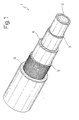
- pipe 1 comprises at least one inner layer 2 of elastomeric material; a fuel vapour barrier layer 3; a second inner layer 4; a spun reinforcing fabric 5 to improve the mechanical strength of the pipe; and a cover layer 6.
- Pipe 1 is purely an example embodiment of the present invention, and may comprise additional layers; the second inner layer may be dispensed with; and the layer thicknesses may vary; all without departing from the scope of the invention.
- the main component of the mixture is preferably a polymer selected from the group consisting of acrylonitrile/butadiene, hydrogenated acrylonitrile/butadiene, chlorosulfonated polyethylene, EPDM, and chlorinated polyethylene.
- inner layer 2 is formed from mixtures of acrylonitrile/butadiene and hydrogenated acrylonitrile/butadiene, or from chlorosulfonated polyethylene.
- Inner layer 2 may be formed using extrusion methods with which any technician in this particular field is familiar.
- the thickness of the inner layer may vary, depending on the polymer selected as the base material, and on average ranges between 1 and 2 mm, preferably between 1.2 and 1.8 mm, and, even more preferably, is about 1.4 mm.
- the inside diameter of pipe 1 may preferably range between 5 and 8 mm, more preferably between 6 and 7 mm, and even more preferably between 6.35 and 6.65 mm; while the outside diameter ranges between 12 and 16 mm, preferably between 14 and 15 mm, and even more preferably between 14.4 and 14.6 mm.
- Inner layer 2 may contain conventional additives, such as reinforcing agents, fillers, pigments, stearic acid, accelerators, curing agents, antioxidants, activators, initiators, plasticizers, wax, precuring inhibitors, and similar.
- carbon black normally added in amounts ranging between 5 and 200 phr
- Talc calcium carbonate, silica and similar, in amounts normally ranging between 5 and 150 phr, or filler-containing oil dispersions may also be added.
- Organosilanes may be used in amounts ranging between 0.1 and 20 phr.
- curing agents those known to any technician in the field may be used, such as free sulfur or sulfur-donating curing agents, e.g.
- the amount added varies according to the type of rubber and the curing agent used, and normally ranges between 0.1 and 10 phr.
- the antidegradants most commonly used in the mixture composition include microcrystalline waxes, paraffin waxes, monophenols, bisphenols, thiophenols, polyphenols, hydroquinone derivatives, phosphites, phosphite mixtures, thioesters, naphthylamines, diphenolamines, substituted and unsubstituted diarylamine derivatives, diarylphenylenediamines, paraphenylenediamines, quinolines, and amine mixtures.
- Antidegradants are normally used in amounts ranging between 0.1 and 10 phr.
- Representative of the process oils which may be used are dithiobisbenzanilide, polyparadinitrosobenzene, xylylmercaptans, polyethylene glycol, petroleum oils, cured vegetable oils, phenol-formaldehyde resins, synthetic oils, petroleum resins, and polymer esters.
- Process oils may be used in conventional amounts of 0 to 140 phr.
- stearic acid is used conventionally in amounts ranging between 1 and 4 phr.
- Conventional additives may also be used, such as calcium oxide, zinc oxide and magnesium oxide, normally in amounts ranging between 0.1 and 25 phr.
- accelerators or accelerator combinations are also used, such as amines, disulfides, guanidine, thiourea, thiazoles, mercaptans, sulfenamides, dithiocarbamates and xanthates, normally in amounts ranging between 0.1 and 100 phr.
- a layer of thermoplastic material in particular, a barrier layer 3 consisting of at least one polyamide, is extruded onto the inner layers of elastomeric material, and preferably comprises polyamides 6/6.6 - i.e. mixtures of polyamide 6.6 and polyamide 6 - also containing known additives such as plasticizers, e.g. polyamide mixtures marketed by ELF ATOCHEM as RILSAN® EM 067 HSP, or polyamide and polyolefin mixtures, such as those marketed by ELF ATOCHEM as ORGALLOY®, more preferably polyamide and polypropylene mixtures, e.g.
- ORGALLOY® RDG 113 polymers with physical-chemical characteristics closely resembling polyamide mixtures and in particular polyamides 6/6.6, and which are therefore also comparable to them when used for barrier layers.
- the thickness of the barrier layer depends on the type of polyamide used, but normally advantageously ranges between 0.1 and 0.3 mm, and preferably between 0.15 and 0.25 mm.
- a FLUOZINC-type antiadhesive may then be added, and yarns of preferably synthetic fibres are then spun around inner layer 2 and barrier layer 3, and possibly around a second inner layer 4, to form spun reinforcing fabric 5 for improving the mechanical strength of the pipe.
- Mainly used are tightly woven, coiled or braided yarns with a polyester or aliphatic or aromatic polyamide fibre base.
- aramidic fibres such as those marketed as KEVLAR® by Du Pont de Nemours, or fibres of TWARON®, an Akzo Nobel trademark.
- a second inner layer 4 is optionally interposed between the barrier layer 3 and the spun reinforcing fabric 5, and comprises a polymer of the same or different chemical nature with respect to inner layer 2, and preferably selected from the group consisting of acrylonitrile/butadiene, hydrogenated acrylonitrile/butadiene, chlorosulfonated polyethylene, EPDM, and chlorinated polyethylene.
- the thickness of layer 4 obviously varies according to the polymer used, but normally ranges between 0.25 and 1.50 mm, and preferably between 0.45 and 0.65 mm.
- the outer or cover layer 6 of elastomeric material is extruded directly onto the underlying structure, and advantageously comprises polymers selected from the group consisting of chlorosulfonated polyethylene, chlorinated polyethylene, acrylonitrile/butadiene and PVC mixtures, EPDM, chloroprene, EVA and EVM.
- the elastomers used are preferably chlorinated polyethylene or EPDM, and more preferably chlorinated polyethylene.
- the thickness of cover layer 6 obviously depends on the nature of the polymer used, and may range between 0.5 and 2.5 mm, preferably between 0.7 and 1.2 mm, and even more preferably between 0.85 and 1.05 mm.
- pipe 1 is cured conventionally at temperatures ranging between 150° and 200°C for preferably 1 to 2 hours.
- a pipe 1 with the structure described above is capable of withstanding working pressures of over 100 bar, unlike currently used petrol pipes of elastomeric material, which have a working pressure resistance of about 10 bar, and a burst pressure of less than 100 bar.
- multilayer pipe 1 combines excellent pressure resistance and very low permeability to petrol vapour.
- a pipe in accordance with the present invention has a burst pressure of over 400 bar, and may therefore be used in direct-injection systems requiring working pressures of over 100 bar.
- the pipe according to the invention requires no noble, intrinsically high-cost polymers, such as fluorinated polymers used in the known state of the art.
- a multilayer pipe in accordance with the present invention is produced by extruding - using known techniques and in known conditions - an inner layer from a mixture of 80 parts by weight of ENICHEM S.p.A. EUROPRENE® N 3345 acrylonitrile/butadiene, and 20 parts by weight of NIPPON ZEON Ltd ZETPOL® 2020L hydrogenated acrylonitrile/butadiene, to which conventional additives as referred to above have been added.
- a barrier layer of ELF ATOCHEM RILSAN® EM 067 HSP consisting of nylon 6/6.6 is then extruded onto the first layer by a second extruder; the pipe is then fed to a third extruder to add a second layer of elastomeric material consisting of PARACRIL® BJLT-M50 (by ENICHEM S.p.A.); and, finally, the pipe so formed is braided with aramidic fibre yarn on an OMA 24-spindle vertical braiding machine.
- the primary yarns are made of AKZO NOBEL TWARON® 1680; three yarns are used for 24 spindles; the spindle tension is fixed at 1.1 kg, and the pitch at about 28.7 mm; and the final diameter of the resulting braid is 12.6 ( ⁇ 0.3) mm.
- the pipe is then covered with a cover layer of chlorinated polyethylene (TYRIN® CM 0730 produced by DUPONT DOW ELASTOMERS) to give a final pipe diameter of 14.4 mm.
- a cover layer of chlorinated polyethylene (TYRIN® CM 0730 produced by DUPONT DOW ELASTOMERS) to give a final pipe diameter of 14.4 mm.
- Table 1 shows the layer composition of a pipe in accordance with the present invention.
- Layer Chemical composition Trade name Supplier Layer thickness Inner layer NBR/HNBR mixture EUROPRENE® ENICHEM/NIPPON ZEON 1,4 mm Inner layer nylon 6/6.6 RILSAN® EM 067 HSP ELF ATOCHEM 0,2 mm Second layer NBR PARACRIL® BJLT-M50 ENICHEM 0,55 mm Reinforcing layer Aramidic fibre yarn TWARON® AKZO NOBEL / Cover layer CPE -chlorinated polyethylene TYRIN® CM 0730 DUPONT DOW 0,95 mm
- Table 2 shows the composition of a known elastomeric petrol pipe with an inner layer made of VITON®, a fluoroelastomer consisting of a terpolymer of vinyl fluoride, hexafluoropropylene and tetrafluoroethylene.
- This type of pipe is typical of the known state of the art, by being used for conducting hydrocarbons, and being impermeable to vapour and resistant to low pressure.
- Table 3 shows the chemical-physical characteristics of polymers used in the barrier layer of a pipe in accordance with the present invention.
- Permeation was measured using the SAE J1737 method, whereby the pipe, fed with a constant stream of petrol, is placed inside a sealed vessel into which dry nitrogen is fed; the dry nitrogen captures and transfers the vapours into a vessel full of active carbon, which adsorbs and retains the petrol vapours.
- the vessel is weighed periodically; the detected increase in weight is caused by the vapours permeating and adsorbed by the carbon; so permeation corresponds to the increase in weight of the active carbon, referred to a linear metre of pipe and over a period of 24 hours.
- the test conditions are shown in Table 4. Petrol pressure 4 bar Petrol temperature 60°C Petrol flow rate 2 l/min Vessel temperature 60°C Carrier gas flow rate 1.5 l/min
- Table 5 shows the respective permeation values of the pipe according to the present invention (indicated 1) with the composition described in Example 1; the comparison pipe (indicated 2) with the composition described in Example 2; and a single-layer pipe of polyamide 12 (indicated 3).
- Pipe 1 2 3 Permeation in g/(m*24 h) 0.014 0.73 0.88
- the permeation value of the pipe according to the present invention is therefore about 1/6 that of the comparison pipes.
Description
| Layer | Chemical composition | Trade name | Supplier | Layer thickness | ||
| Inner layer | NBR/HNBR mixture | EUROPRENE® | ENICHEM/ | 1,4 mm | ||
| | nylon | 6/6.6 | RILSAN® EM 067 | ELF ATOCHEM | 0,2 mm | |
| Second layer | NBR | PARACRIL® BJLT-M50 | ENICHEM | 0,55 mm | ||
| Reinforcing layer | Aramidic fibre yarn | TWARON® | AKZO NOBEL | / | ||
| Cover layer | CPE -chlorinated polyethylene | TYRIN® CM 0730 | DUPONT DOW | 0,95 mm |
| Layer | Chemical composition | Trade name | Supplier | Layer thickness |
| First inner layer | Fluoroelastomer Terpolymer of vinyl fluoride | FKM VITON® | DUPONT DOW ELASTOMERS | 0,63 mm |
| Second inner layer | Chlorinated polyethylene | HYDRIN® C 65 | | 2,3 mm |
| Reinforcing layer | Aramidic fibre yarn | KEVLAR® | DUPONT DOW ELASTOMERS | / |
| Outer layer | Chlorinated polyethylene | HYDRIN® C 65 | | 2,6 mm |
| Property | ASTM measuring method | Unit | RILSAN EM 067 HSP | ORGALLOY RDG 113 |
| Melting point, DSC | D3418 | °C | 221 | 229 |
| Breaking strength | D638 | KN/m2 | 62052 | 72394 |
| Extensibility | D638 | % | 330 | 290 |
| Flexural modulus, Tangent | D790 | KN/m2 | 413854 | 2482112 |
| | 4 bar |
| Petrol temperature | 60°C |
| Petrol flow rate | 2 l/min |
| Vessel temperature | 60°C |
| Carrier gas flow rate | 1.5 l/min |
| Pipe | 1 | 2 | 3 |
| Permeation in g/(m*24 h) | 0.014 | 0.73 | 0.88 |
| Test | Results |
| Burst pressure | 731 |
| Volume expansion at 100 bar cc/ | 5 cc/m |
| 100 bar % change in length | -2.2 % |
| Inside diameter (mm) | 7.7 mm |
| Outside diameter (mm) | 14.5 mm |
| Concentricity | 0.14 mm |
| Ozone resistance 50 pphm for 72 hours at 38°C | no break |
| Low-temperature flexibility 24 hours at -40°C | no break |
Claims (17)
- A multilayer pipe (1) for conducting hydrocarbons, and comprising at least one inner layer (2) of elastomeric material; a barrier layer (3) said barrier layer comprising at least a polyamide; a reinforcing spun fabric (5) comprising fibres; and a cover layer (6) of elastomeric material; characterized in that said inner layer (2) comprises at least one material selected from the group consisting of acrylonitrile/butadiene, hydrogenated acrylonitrile/butadiene, chlorosulfonated polyethylene, EPDM, and chlorinated polyethylene.
- A multilayer pipe as claimed in Claim 1, characterized in that said fibres are obtained from a polymer selected from the group consisting of aliphatic polyamides, aromatic polyamides, and polyesters.
- A multilayer pipe as claimed in any one of the foregoing Claims, characterized in that said cover layer (6) comprises a material selected from the group consisting of chlorosulfonated polyethylene, chlorinated polyethylene, acrylonitrile/butadiene and PVC mixtures, chlorinated polyethylene, EPDM, chloroprene, EVA and EVM.
- A multilayer pipe for conducting hydrocarbons and including at least one inner layer (2) comprising a material selected from the group consisting of acrylonitrile/butadiene, hydrogenated acrylonitrile/butadiene, chlorosulfonated polyethylene, EPDM, and chlorinated polyethylene; a barrier layer (3) comprising a material selected from the group consisting of aliphatic or aromatic polyamides, polyamide mixtures, and polyamide and polyolefin mixtures; a reinforcing spun fabric (5) consisting of fibres of a material selected from the group consisting of aliphatic polyamides, aromatic polyamides, and polyesters; and a cover layer (6) comprising a material selected from the group consisting of chlorosulfonated polyethylene, chlorinated polyethylene, acrylonitrile/butadiene and PVC mixtures, chlorinated polyethylene, EPDM, chloroprene, EVA and EVM.
- A multilayer pipe as claimed in Claims 1 to 4, characterized in that said barrier layer (3) comprises a mixture of polyamide 6 and polyamide 6/6.
- A multilayer pipe as claimed in Claims 1 to 5, characterized in that said barrier layer (3) comprises mixtures of polyamide and polyolefins.
- A multilayer pipe as claimed in Claim 6, characterized in that said polyolefins are polypropylene.
- A multilayer pipe as claimed in any one of the foregoing Claims, characterized in that said fibres are obtained from aromatic polyamides.
- A multilayer pipe as claimed in any one of the foregoing Claims, characterized in that said inner layer (2) comprises acrylonitrile/butadiene.
- A multilayer pipe as claimed in Claim 9, characterized in that said inner layer (2) also comprises hydrogenated acrylonitrile/butadiene.
- A multilayer pipe as claimed in any one of the foregoing Claims, characterized by also comprising a second inner layer (4) interposed between said barrier layer (3) and said cover layer (6).
- A multilayer pipe as claimed in Claim 11, characterized in that said second inner layer (4) comprises a material selected from the group consisting of acrylonitrile/butadiene, hydrogenated acrylonitrile/butadiene, chlorosulfonated polyethylene, EPDM, and chlorinated polyethylene.
- A multilayer pipe as claimed in Claim 12, characterized in that said second inner layer (4) comprises acrylonitrile/butadiene.
- A multilayer pipe as claimed in Claim 13, characterized in that said cover layer (6) comprises chlorinated polyethylene.
- A multilayer pipe as claimed in any one of the foregoing Claims, characterized in that said inner layer (2) is of a thickness ranging between 1 and 2 mm; said barrier layer (3) is of a thickness ranging between 0.1 and 0.3 mm; and said cover layer (6) is of a thickness ranging between 0.50 and 2.50 mm;
by having a permeation value of less than 0.050 g/(m*24h) when permeation tested as per SAE standard J1737; and by being capable of withstanding a pressure of over 100 bar. - A multilayer pipe as claimed in any one of Claims 1 to 15, characterized in that said inner layer (2) is of a thickness ranging between 1.2 and 1.8 mm; said barrier layer (3) is of a thickness ranging between 0.15 and 0.25 mm; and said cover layer (6) is of a thickness ranging between 0.85 and 1.05 mm.
- Use of a multilayer pipe as claimed in any one of the foregoing Claims for conducting fuel directly from a vehicle pump to the engine compartment.
Applications Claiming Priority (2)
| Application Number | Priority Date | Filing Date | Title |
|---|---|---|---|
| ITTO990433 | 1999-05-21 | ||
| IT1999TO000433A IT1308043B1 (en) | 1999-05-21 | 1999-05-21 | MULTI-LAYER FUEL TUBE |
Publications (3)
| Publication Number | Publication Date |
|---|---|
| EP1054202A2 EP1054202A2 (en) | 2000-11-22 |
| EP1054202A3 EP1054202A3 (en) | 2001-06-20 |
| EP1054202B1 true EP1054202B1 (en) | 2004-04-21 |
Family
ID=11417833
Family Applications (1)
| Application Number | Title | Priority Date | Filing Date |
|---|---|---|---|
| EP00110512A Expired - Lifetime EP1054202B1 (en) | 1999-05-21 | 2000-05-17 | Multilayer fuel pipe |
Country Status (8)
| Country | Link |
|---|---|
| US (1) | US6435217B1 (en) |
| EP (1) | EP1054202B1 (en) |
| AR (1) | AR024029A1 (en) |
| AT (1) | ATE265011T1 (en) |
| BR (1) | BR0007326A (en) |
| DE (1) | DE60009982T2 (en) |
| ES (1) | ES2216758T3 (en) |
| IT (1) | IT1308043B1 (en) |
Cited By (2)
| Publication number | Priority date | Publication date | Assignee | Title |
|---|---|---|---|---|
| DE202009006553U1 (en) * | 2009-05-07 | 2010-10-21 | Rehau Ag + Co. | Pipe or pipe fitting |
| DE102011089616A1 (en) * | 2011-12-22 | 2013-06-27 | Fränkische Industrial Pipes GmbH & Co. KG | Multi-layer fuel line |
Families Citing this family (21)
| Publication number | Priority date | Publication date | Assignee | Title |
|---|---|---|---|---|
| FR2802272B1 (en) * | 1999-12-09 | 2002-06-07 | Nobel Plastiques | PIPING FOR AUTOMOTIVE FLUID |
| DE10065177A1 (en) * | 2000-12-23 | 2002-06-27 | Degussa | Multi-layer composite based on polyamide / polyolefin |
| NL1019627C2 (en) * | 2001-12-20 | 2003-06-24 | Pipelife Nederland Bv | Reinforced permeation-tight plastic pipe. |
| EP1492671A1 (en) * | 2002-04-11 | 2005-01-05 | Avon Property Management Co. | Fuel filler hose |
| JP2003336772A (en) * | 2002-05-17 | 2003-11-28 | Goodyear Tire & Rubber Co:The | Power steering hose |
| FR2841630B1 (en) * | 2002-07-01 | 2004-08-06 | Atofina | FLEXIBLE POLYAMIDE PIPES FOR COMPRESSED AIR |
| JP2004332892A (en) * | 2003-05-12 | 2004-11-25 | Tokai Rubber Ind Ltd | Fiber reinforced hose |
| DE10322026B4 (en) * | 2003-05-16 | 2009-01-22 | Veritas Ag | Multilayer hose |
| BRPI0402579A (en) * | 2003-07-11 | 2005-05-31 | Goodyear Tire & Rubber | Air conditioning hose |
| FR2857733B1 (en) | 2003-07-15 | 2006-10-20 | Hutchinson | TUBULAR ELEMENT FOR AIR CONDITIONING CIRCUIT. |
| US20070048475A1 (en) * | 2005-08-31 | 2007-03-01 | The Goodyear Tire & Rubber Company | Refrigerant hose |
| US7572745B2 (en) * | 2006-09-26 | 2009-08-11 | The Gates Corporation | Fluid transfer hose reinforced with hybrid yarn |
| US8426524B2 (en) * | 2006-12-06 | 2013-04-23 | Veyance Technologies, Inc | Elastomeric blend for vehicle timing belt |
| JP2008246752A (en) * | 2007-03-29 | 2008-10-16 | Tokai Rubber Ind Ltd | Heat-resistant rubber hose for diesel |
| US9592648B2 (en) * | 2009-06-01 | 2017-03-14 | Gates Corporation | Low-permeation flexible fuel hose |
| US20180045343A1 (en) * | 2010-10-19 | 2018-02-15 | Contitech Techno-Chemie Gmbh | Fluid resistant high temperature hose |
| US20120090720A1 (en) * | 2010-10-19 | 2012-04-19 | Veyance Technologies, Inc. | Fluid resistant high temperature hose |
| GB201109876D0 (en) | 2011-06-13 | 2011-07-27 | Oceaneering Internat Services Ltd | Umbilical hose with improved ovalisation resistance |
| GB201303619D0 (en) * | 2013-02-28 | 2013-04-17 | Valpar Ind Ltd | Improved beverage dispensing tubing |
| RU2672233C2 (en) * | 2014-06-26 | 2018-11-12 | Сано Индастриал Ко., Лтд. | Tubular moulded article |
| US20220275886A1 (en) * | 2019-07-31 | 2022-09-01 | Danfoss Power Solutions Ii Technology A/S | Low permeation type c air conditioning hose |
Family Cites Families (11)
| Publication number | Priority date | Publication date | Assignee | Title |
|---|---|---|---|---|
| JPH01141047A (en) * | 1987-11-28 | 1989-06-02 | Tokai Rubber Ind Ltd | Refrigerant transport hose |
| US4907625A (en) * | 1987-12-28 | 1990-03-13 | Tokai Rubber Industries, Ltd. | Refregerant transporting hose |
| JPH0620945Y2 (en) * | 1988-03-15 | 1994-06-01 | 豊田合成株式会社 | Reinforced hose |
| JPH072403B2 (en) * | 1988-06-06 | 1995-01-18 | 東海ゴム工業株式会社 | Refrigerant transport hose |
| JP2706814B2 (en) * | 1989-05-29 | 1998-01-28 | 東海ゴム工業株式会社 | Rubber laminate |
| DE4001125C1 (en) * | 1989-11-20 | 1990-12-13 | Technoform Caprano + Brunnhofer Kg, 3501 Fuldabrueck, De | |
| JP2704096B2 (en) * | 1992-06-19 | 1998-01-26 | 横浜ゴム株式会社 | hose |
| DE4414955C1 (en) * | 1994-04-28 | 1995-09-21 | Inventa Ag | Extruded multi-layer polymer tubing or tubing |
| DE19633133C1 (en) * | 1996-08-16 | 1998-03-05 | Veritas Gummiwerke Ag | Tough, dimensionally-stable multilayer tubing |
| US5957164A (en) | 1998-09-10 | 1999-09-28 | Aeroquip Corporation | Refrigerant hose |
| JP2000146034A (en) * | 1998-11-06 | 2000-05-26 | Tokai Rubber Ind Ltd | Refrigerant hose for motor-driven compressor |
-
1999
- 1999-05-21 IT IT1999TO000433A patent/IT1308043B1/en active
-
2000
- 2000-05-15 US US09/571,662 patent/US6435217B1/en not_active Expired - Lifetime
- 2000-05-17 ES ES00110512T patent/ES2216758T3/en not_active Expired - Lifetime
- 2000-05-17 DE DE60009982T patent/DE60009982T2/en not_active Expired - Lifetime
- 2000-05-17 EP EP00110512A patent/EP1054202B1/en not_active Expired - Lifetime
- 2000-05-17 AT AT00110512T patent/ATE265011T1/en not_active IP Right Cessation
- 2000-05-19 AR ARP000102424A patent/AR024029A1/en unknown
- 2000-05-22 BR BR0007326-1A patent/BR0007326A/en active Pending
Cited By (2)
| Publication number | Priority date | Publication date | Assignee | Title |
|---|---|---|---|---|
| DE202009006553U1 (en) * | 2009-05-07 | 2010-10-21 | Rehau Ag + Co. | Pipe or pipe fitting |
| DE102011089616A1 (en) * | 2011-12-22 | 2013-06-27 | Fränkische Industrial Pipes GmbH & Co. KG | Multi-layer fuel line |
Also Published As
| Publication number | Publication date |
|---|---|
| EP1054202A3 (en) | 2001-06-20 |
| ITTO990433A1 (en) | 2000-11-21 |
| DE60009982T2 (en) | 2005-05-04 |
| AR024029A1 (en) | 2002-09-04 |
| BR0007326A (en) | 2001-10-02 |
| ES2216758T3 (en) | 2004-11-01 |
| ATE265011T1 (en) | 2004-05-15 |
| EP1054202A2 (en) | 2000-11-22 |
| IT1308043B1 (en) | 2001-11-29 |
| DE60009982D1 (en) | 2004-05-27 |
| US6435217B1 (en) | 2002-08-20 |
Similar Documents
| Publication | Publication Date | Title |
|---|---|---|
| EP1054202B1 (en) | Multilayer fuel pipe | |
| US4984604A (en) | Rubber hose | |
| KR100392800B1 (en) | Hose construction containing fluoroplastic terpolymers | |
| CN110461586B (en) | High-pressure compact spiral hydraulic hose | |
| US5941286A (en) | Composite fuel and vapor barrier tube and process for making same | |
| EP2444243B1 (en) | Fluid resistant high temperature hose | |
| EP0203880B1 (en) | Hose construction | |
| DE60213962T2 (en) | TUBULAR POLYMER COMPOSITES FOR TUBE AND HOSE CONSTRUCTION | |
| KR101118818B1 (en) | Thermoplastic multilayer composite in form of hollow body having sour-gas resistance and low temperature impact property | |
| EP0999394B1 (en) | Hose construction containing ternary blend of polymers | |
| US20090123683A1 (en) | Low-Permeation Flexible Fuel Hose | |
| US20090151805A1 (en) | Blow-out prevention hose bundle for offshore oil rigs | |
| US20180045343A1 (en) | Fluid resistant high temperature hose | |
| EP0716632B1 (en) | Composite fuel and vapor barrier tube and process for making same | |
| US20200269539A1 (en) | Low extractable hose | |
| EP2321121B1 (en) | Pipe comprising a layer comprising a fluorinated plastomer and an elastomeric material | |
| US20220260185A1 (en) | Fiber reinforced hoses, composite materials and articles, and related methods | |
| US10781946B1 (en) | All rubber low sulfur and extraction PED hose | |
| US20220268377A1 (en) | Sustainable industrial hose | |
| US20220055336A1 (en) | Sustainable industrial hose | |
| US20220057024A1 (en) | Sustainable industrial hose | |
| US20220258440A1 (en) | Fiber reinforced composite materials, articles and related methods | |
| Ridland et al. | New Compounding Techniques for Improved Hose Performance |
Legal Events
| Date | Code | Title | Description |
|---|---|---|---|
| PUAI | Public reference made under article 153(3) epc to a published international application that has entered the european phase |
Free format text: ORIGINAL CODE: 0009012 |
|
| AK | Designated contracting states |
Kind code of ref document: A2 Designated state(s): AT BE CH CY DE DK ES FI FR GB GR IE IT LI LU MC NL PT SE |
|
| AX | Request for extension of the european patent |
Free format text: AL;LT;LV;MK;RO;SI |
|
| PUAL | Search report despatched |
Free format text: ORIGINAL CODE: 0009013 |
|
| AK | Designated contracting states |
Kind code of ref document: A3 Designated state(s): AT BE CH CY DE DK ES FI FR GB GR IE IT LI LU MC NL PT SE |
|
| AX | Request for extension of the european patent |
Free format text: AL;LT;LV;MK;RO;SI |
|
| RIC1 | Information provided on ipc code assigned before grant |
Free format text: 7F 16L 11/08 A, 7F 16L 11/12 B, 7F 16L 9/12 B |
|
| 17P | Request for examination filed |
Effective date: 20011219 |
|
| AKX | Designation fees paid |
Free format text: AT BE CH CY DE DK ES FI FR GB GR IE IT LI LU MC NL PT SE |
|
| 17Q | First examination report despatched |
Effective date: 20030402 |
|
| GRAP | Despatch of communication of intention to grant a patent |
Free format text: ORIGINAL CODE: EPIDOSNIGR1 |
|
| GRAS | Grant fee paid |
Free format text: ORIGINAL CODE: EPIDOSNIGR3 |
|
| GRAA | (expected) grant |
Free format text: ORIGINAL CODE: 0009210 |
|
| RAP1 | Party data changed (applicant data changed or rights of an application transferred) |
Owner name: DAYCO FLUID TECHNOLOGIES S.P.A. |
|
| AK | Designated contracting states |
Kind code of ref document: B1 Designated state(s): AT BE CH CY DE DK ES FI FR GB GR IE IT LI LU MC NL PT SE |
|
| PG25 | Lapsed in a contracting state [announced via postgrant information from national office to epo] |
Ref country code: FI Free format text: LAPSE BECAUSE OF FAILURE TO SUBMIT A TRANSLATION OF THE DESCRIPTION OR TO PAY THE FEE WITHIN THE PRESCRIBED TIME-LIMIT Effective date: 20040421 Ref country code: NL Free format text: LAPSE BECAUSE OF FAILURE TO SUBMIT A TRANSLATION OF THE DESCRIPTION OR TO PAY THE FEE WITHIN THE PRESCRIBED TIME-LIMIT Effective date: 20040421 Ref country code: LI Free format text: LAPSE BECAUSE OF FAILURE TO SUBMIT A TRANSLATION OF THE DESCRIPTION OR TO PAY THE FEE WITHIN THE PRESCRIBED TIME-LIMIT Effective date: 20040421 Ref country code: AT Free format text: LAPSE BECAUSE OF FAILURE TO SUBMIT A TRANSLATION OF THE DESCRIPTION OR TO PAY THE FEE WITHIN THE PRESCRIBED TIME-LIMIT Effective date: 20040421 Ref country code: BE Free format text: LAPSE BECAUSE OF FAILURE TO SUBMIT A TRANSLATION OF THE DESCRIPTION OR TO PAY THE FEE WITHIN THE PRESCRIBED TIME-LIMIT Effective date: 20040421 Ref country code: CH Free format text: LAPSE BECAUSE OF FAILURE TO SUBMIT A TRANSLATION OF THE DESCRIPTION OR TO PAY THE FEE WITHIN THE PRESCRIBED TIME-LIMIT Effective date: 20040421 Ref country code: CY Free format text: LAPSE BECAUSE OF FAILURE TO SUBMIT A TRANSLATION OF THE DESCRIPTION OR TO PAY THE FEE WITHIN THE PRESCRIBED TIME-LIMIT Effective date: 20040421 |
|
| REG | Reference to a national code |
Ref country code: GB Ref legal event code: FG4D |
|
| REG | Reference to a national code |
Ref country code: CH Ref legal event code: EP |
|
| PG25 | Lapsed in a contracting state [announced via postgrant information from national office to epo] |
Ref country code: IE Free format text: LAPSE BECAUSE OF NON-PAYMENT OF DUE FEES Effective date: 20040517 Ref country code: LU Free format text: LAPSE BECAUSE OF NON-PAYMENT OF DUE FEES Effective date: 20040517 |
|
| REG | Reference to a national code |
Ref country code: IE Ref legal event code: FG4D |
|
| REF | Corresponds to: |
Ref document number: 60009982 Country of ref document: DE Date of ref document: 20040527 Kind code of ref document: P |
|
| PG25 | Lapsed in a contracting state [announced via postgrant information from national office to epo] |
Ref country code: MC Free format text: LAPSE BECAUSE OF NON-PAYMENT OF DUE FEES Effective date: 20040531 |
|
| REG | Reference to a national code |
Ref country code: SE Ref legal event code: TRGR |
|
| PG25 | Lapsed in a contracting state [announced via postgrant information from national office to epo] |
Ref country code: GR Free format text: LAPSE BECAUSE OF FAILURE TO SUBMIT A TRANSLATION OF THE DESCRIPTION OR TO PAY THE FEE WITHIN THE PRESCRIBED TIME-LIMIT Effective date: 20040721 Ref country code: DK Free format text: LAPSE BECAUSE OF FAILURE TO SUBMIT A TRANSLATION OF THE DESCRIPTION OR TO PAY THE FEE WITHIN THE PRESCRIBED TIME-LIMIT Effective date: 20040721 |
|
| NLV1 | Nl: lapsed or annulled due to failure to fulfill the requirements of art. 29p and 29m of the patents act | ||
| REG | Reference to a national code |
Ref country code: CH Ref legal event code: PL |
|
| REG | Reference to a national code |
Ref country code: ES Ref legal event code: FG2A Ref document number: 2216758 Country of ref document: ES Kind code of ref document: T3 |
|
| ET | Fr: translation filed | ||
| REG | Reference to a national code |
Ref country code: IE Ref legal event code: MM4A |
|
| PLBE | No opposition filed within time limit |
Free format text: ORIGINAL CODE: 0009261 |
|
| STAA | Information on the status of an ep patent application or granted ep patent |
Free format text: STATUS: NO OPPOSITION FILED WITHIN TIME LIMIT |
|
| 26N | No opposition filed |
Effective date: 20050124 |
|
| PG25 | Lapsed in a contracting state [announced via postgrant information from national office to epo] |
Ref country code: PT Free format text: LAPSE BECAUSE OF NON-PAYMENT OF DUE FEES Effective date: 20040921 |
|
| PGFP | Annual fee paid to national office [announced via postgrant information from national office to epo] |
Ref country code: ES Payment date: 20090513 Year of fee payment: 10 |
|
| PG25 | Lapsed in a contracting state [announced via postgrant information from national office to epo] |
Ref country code: IT Free format text: LAPSE BECAUSE OF NON-PAYMENT OF DUE FEES Effective date: 20080517 |
|
| PGFP | Annual fee paid to national office [announced via postgrant information from national office to epo] |
Ref country code: SE Payment date: 20090518 Year of fee payment: 10 |
|
| PGFP | Annual fee paid to national office [announced via postgrant information from national office to epo] |
Ref country code: GB Payment date: 20090519 Year of fee payment: 10 |
|
| GBPC | Gb: european patent ceased through non-payment of renewal fee |
Effective date: 20100517 |
|
| EUG | Se: european patent has lapsed | ||
| PG25 | Lapsed in a contracting state [announced via postgrant information from national office to epo] |
Ref country code: SE Free format text: LAPSE BECAUSE OF NON-PAYMENT OF DUE FEES Effective date: 20100518 |
|
| REG | Reference to a national code |
Ref country code: ES Ref legal event code: FD2A Effective date: 20110714 |
|
| PG25 | Lapsed in a contracting state [announced via postgrant information from national office to epo] |
Ref country code: GB Free format text: LAPSE BECAUSE OF NON-PAYMENT OF DUE FEES Effective date: 20100517 Ref country code: ES Free format text: LAPSE BECAUSE OF NON-PAYMENT OF DUE FEES Effective date: 20110704 |
|
| PGRI | Patent reinstated in contracting state [announced from national office to epo] |
Ref country code: IT Effective date: 20110616 |
|
| PG25 | Lapsed in a contracting state [announced via postgrant information from national office to epo] |
Ref country code: ES Free format text: LAPSE BECAUSE OF NON-PAYMENT OF DUE FEES Effective date: 20100518 |
|
| PGFP | Annual fee paid to national office [announced via postgrant information from national office to epo] |
Ref country code: IT Payment date: 20140523 Year of fee payment: 15 Ref country code: DE Payment date: 20140515 Year of fee payment: 15 Ref country code: FR Payment date: 20140509 Year of fee payment: 15 |
|
| REG | Reference to a national code |
Ref country code: DE Ref legal event code: R119 Ref document number: 60009982 Country of ref document: DE |
|
| PG25 | Lapsed in a contracting state [announced via postgrant information from national office to epo] |
Ref country code: IT Free format text: LAPSE BECAUSE OF NON-PAYMENT OF DUE FEES Effective date: 20150517 |
|
| REG | Reference to a national code |
Ref country code: FR Ref legal event code: ST Effective date: 20160129 |
|
| PG25 | Lapsed in a contracting state [announced via postgrant information from national office to epo] |
Ref country code: DE Free format text: LAPSE BECAUSE OF NON-PAYMENT OF DUE FEES Effective date: 20151201 |
|
| PG25 | Lapsed in a contracting state [announced via postgrant information from national office to epo] |
Ref country code: FR Free format text: LAPSE BECAUSE OF NON-PAYMENT OF DUE FEES Effective date: 20150601 |