EP1054201B1 - Pipe clamp - Google Patents
Pipe clamp Download PDFInfo
- Publication number
- EP1054201B1 EP1054201B1 EP00113142A EP00113142A EP1054201B1 EP 1054201 B1 EP1054201 B1 EP 1054201B1 EP 00113142 A EP00113142 A EP 00113142A EP 00113142 A EP00113142 A EP 00113142A EP 1054201 B1 EP1054201 B1 EP 1054201B1
- Authority
- EP
- European Patent Office
- Prior art keywords
- pipe
- clamp
- length
- lengths
- members
- Prior art date
- Legal status (The legal status is an assumption and is not a legal conclusion. Google has not performed a legal analysis and makes no representation as to the accuracy of the status listed.)
- Expired - Lifetime
Links
Images


Classifications
-
- F—MECHANICAL ENGINEERING; LIGHTING; HEATING; WEAPONS; BLASTING
- F16—ENGINEERING ELEMENTS AND UNITS; GENERAL MEASURES FOR PRODUCING AND MAINTAINING EFFECTIVE FUNCTIONING OF MACHINES OR INSTALLATIONS; THERMAL INSULATION IN GENERAL
- F16L—PIPES; JOINTS OR FITTINGS FOR PIPES; SUPPORTS FOR PIPES, CABLES OR PROTECTIVE TUBING; MEANS FOR THERMAL INSULATION IN GENERAL
- F16L1/00—Laying or reclaiming pipes; Repairing or joining pipes on or under water
- F16L1/024—Laying or reclaiming pipes on land, e.g. above the ground
- F16L1/06—Accessories therefor, e.g. anchors
-
- B—PERFORMING OPERATIONS; TRANSPORTING
- B29—WORKING OF PLASTICS; WORKING OF SUBSTANCES IN A PLASTIC STATE IN GENERAL
- B29C—SHAPING OR JOINING OF PLASTICS; SHAPING OF MATERIAL IN A PLASTIC STATE, NOT OTHERWISE PROVIDED FOR; AFTER-TREATMENT OF THE SHAPED PRODUCTS, e.g. REPAIRING
- B29C65/00—Joining or sealing of preformed parts, e.g. welding of plastics materials; Apparatus therefor
- B29C65/78—Means for handling the parts to be joined, e.g. for making containers or hollow articles, e.g. means for handling sheets, plates, web-like materials, tubular articles, hollow articles or elements to be joined therewith; Means for discharging the joined articles from the joining apparatus
- B29C65/7802—Positioning the parts to be joined, e.g. aligning, indexing or centring
-
- B—PERFORMING OPERATIONS; TRANSPORTING
- B29—WORKING OF PLASTICS; WORKING OF SUBSTANCES IN A PLASTIC STATE IN GENERAL
- B29C—SHAPING OR JOINING OF PLASTICS; SHAPING OF MATERIAL IN A PLASTIC STATE, NOT OTHERWISE PROVIDED FOR; AFTER-TREATMENT OF THE SHAPED PRODUCTS, e.g. REPAIRING
- B29C66/00—General aspects of processes or apparatus for joining preformed parts
- B29C66/01—General aspects dealing with the joint area or with the area to be joined
- B29C66/05—Particular design of joint configurations
- B29C66/10—Particular design of joint configurations particular design of the joint cross-sections
- B29C66/11—Joint cross-sections comprising a single joint-segment, i.e. one of the parts to be joined comprising a single joint-segment in the joint cross-section
- B29C66/112—Single lapped joints
- B29C66/1122—Single lap to lap joints, i.e. overlap joints
-
- B—PERFORMING OPERATIONS; TRANSPORTING
- B29—WORKING OF PLASTICS; WORKING OF SUBSTANCES IN A PLASTIC STATE IN GENERAL
- B29C—SHAPING OR JOINING OF PLASTICS; SHAPING OF MATERIAL IN A PLASTIC STATE, NOT OTHERWISE PROVIDED FOR; AFTER-TREATMENT OF THE SHAPED PRODUCTS, e.g. REPAIRING
- B29C66/00—General aspects of processes or apparatus for joining preformed parts
- B29C66/01—General aspects dealing with the joint area or with the area to be joined
- B29C66/05—Particular design of joint configurations
- B29C66/10—Particular design of joint configurations particular design of the joint cross-sections
- B29C66/11—Joint cross-sections comprising a single joint-segment, i.e. one of the parts to be joined comprising a single joint-segment in the joint cross-section
- B29C66/114—Single butt joints
- B29C66/1142—Single butt to butt joints
-
- B—PERFORMING OPERATIONS; TRANSPORTING
- B29—WORKING OF PLASTICS; WORKING OF SUBSTANCES IN A PLASTIC STATE IN GENERAL
- B29C—SHAPING OR JOINING OF PLASTICS; SHAPING OF MATERIAL IN A PLASTIC STATE, NOT OTHERWISE PROVIDED FOR; AFTER-TREATMENT OF THE SHAPED PRODUCTS, e.g. REPAIRING
- B29C66/00—General aspects of processes or apparatus for joining preformed parts
- B29C66/50—General aspects of joining tubular articles; General aspects of joining long products, i.e. bars or profiled elements; General aspects of joining single elements to tubular articles, hollow articles or bars; General aspects of joining several hollow-preforms to form hollow or tubular articles
- B29C66/51—Joining tubular articles, profiled elements or bars; Joining single elements to tubular articles, hollow articles or bars; Joining several hollow-preforms to form hollow or tubular articles
- B29C66/52—Joining tubular articles, bars or profiled elements
- B29C66/522—Joining tubular articles
- B29C66/5221—Joining tubular articles for forming coaxial connections, i.e. the tubular articles to be joined forming a zero angle relative to each other
-
- B—PERFORMING OPERATIONS; TRANSPORTING
- B29—WORKING OF PLASTICS; WORKING OF SUBSTANCES IN A PLASTIC STATE IN GENERAL
- B29C—SHAPING OR JOINING OF PLASTICS; SHAPING OF MATERIAL IN A PLASTIC STATE, NOT OTHERWISE PROVIDED FOR; AFTER-TREATMENT OF THE SHAPED PRODUCTS, e.g. REPAIRING
- B29C66/00—General aspects of processes or apparatus for joining preformed parts
- B29C66/50—General aspects of joining tubular articles; General aspects of joining long products, i.e. bars or profiled elements; General aspects of joining single elements to tubular articles, hollow articles or bars; General aspects of joining several hollow-preforms to form hollow or tubular articles
- B29C66/51—Joining tubular articles, profiled elements or bars; Joining single elements to tubular articles, hollow articles or bars; Joining several hollow-preforms to form hollow or tubular articles
- B29C66/52—Joining tubular articles, bars or profiled elements
- B29C66/522—Joining tubular articles
- B29C66/5229—Joining tubular articles involving the use of a socket
- B29C66/52298—Joining tubular articles involving the use of a socket said socket being composed by several elements
-
- F—MECHANICAL ENGINEERING; LIGHTING; HEATING; WEAPONS; BLASTING
- F16—ENGINEERING ELEMENTS AND UNITS; GENERAL MEASURES FOR PRODUCING AND MAINTAINING EFFECTIVE FUNCTIONING OF MACHINES OR INSTALLATIONS; THERMAL INSULATION IN GENERAL
- F16L—PIPES; JOINTS OR FITTINGS FOR PIPES; SUPPORTS FOR PIPES, CABLES OR PROTECTIVE TUBING; MEANS FOR THERMAL INSULATION IN GENERAL
- F16L1/00—Laying or reclaiming pipes; Repairing or joining pipes on or under water
- F16L1/024—Laying or reclaiming pipes on land, e.g. above the ground
- F16L1/028—Laying or reclaiming pipes on land, e.g. above the ground in the ground
-
- B—PERFORMING OPERATIONS; TRANSPORTING
- B29—WORKING OF PLASTICS; WORKING OF SUBSTANCES IN A PLASTIC STATE IN GENERAL
- B29C—SHAPING OR JOINING OF PLASTICS; SHAPING OF MATERIAL IN A PLASTIC STATE, NOT OTHERWISE PROVIDED FOR; AFTER-TREATMENT OF THE SHAPED PRODUCTS, e.g. REPAIRING
- B29C66/00—General aspects of processes or apparatus for joining preformed parts
- B29C66/70—General aspects of processes or apparatus for joining preformed parts characterised by the composition, physical properties or the structure of the material of the parts to be joined; Joining with non-plastics material
- B29C66/71—General aspects of processes or apparatus for joining preformed parts characterised by the composition, physical properties or the structure of the material of the parts to be joined; Joining with non-plastics material characterised by the composition of the plastics material of the parts to be joined
Definitions
- the present invention relates to a clamp to be used in joining together of two adjacent pipe lengths with adjacent ends curving with substantially the same sense.
- the pipe is fed as a coil from a reel, coiler or drum on which the pipe is wound. After a suitable length has been wound from the coiler it is cut from the coil and laid in the trench which has already been dug.
- the near end of the trench-lying pipe is arranged to extend upwardly from the trench so that it terminates above ground level.
- the near end has an upwardly directed curve because the pipe has been stored as a coil and has assumed a slight curve along its length.
- the ends of the pipe lengths may initially curve in a substantially upward direction.
- One of the pipe lengths may be fed from a coil to a position where it lies on the ground.
- the end of the coiled pipe length is rotated so that it curves in a substantially downward direction.
- the curved end on leaving the coil the curved end may be caused to lie on the ground with its curve parallel to the ground then the end is raised in such a manner that it rotates to a position where it curves in a substantially downward direction.
- the other pipe length may be located in a trench with its end curving upwardly.
- the pipe lengths are suitably of a flexible material, conveniently plastics and preferably polyethylene.
- a pipeline comprises at least two discrete lengths of pipe joined together at adjacent ends, the leading end of each length except that length which is leading having been rotated about their axis substantially by 180°.
- a trench 1 is dug and in it is located a first length 2 of previously coiled pipe of approximately 100 metres in length, the length 2 having been cut from a coil 3 of pipe wound onto the reel, coiler or drum 4 distanced from the near end 5 of the trench 1.
- the length 2 of pipe which is of a suitable plastics material such as polyethylene, is manhandled into the trench 1 and a near end 6 of the length 2 (with respect to the reel 4) projects from the near end 5 of the trench with an upwardly directed curve to terminate above ground level. As previously explained the curve is caused because the pipe is stored as a coil on the reel 4.
- a second length 7 of pipe is wound from the reel 4 and has an end 8 which also curves in upward direction but opposite to that of the first length 2.
- end 8 which also curves in upward direction but opposite to that of the first length 2.
- a length 7 of pipe is wound from the reel 4 sufficient that its end 8 lies adjacent the length 2 and the length 7 is then allowed to rest on the ground, its weight causing it to rotate about its axis by 90° so that its curve lies parallel to the ground.
- a pipe clamp 10 (to be described fully later) is clamped around the end 8 of length 7 with the connecting plate 11 of the clamp 10 positioned on the side of the pipe length 7 opposite to the centre of a notional circle which the pipe end 8 would form if its curve continued endlessly.
- the plate 11 is then connected by a rope or strop 12 to the bucket 13 of a mechanical excavator (not shown).
- the pipe end 8 of the length 7 now curves in a downward direction and therefore in a substantially opposite sense to the upward curve of the end 6 of length 2. This enables the two ends to be brought together quite easily and joined by any convenient technique such as butt-fusion welding or the like.
- the pipe clamp 10 is cylindrical and comprises two semi-circular jaws 13 and 14 which can be brought together around the circumference of a length of pipe 7 and which are connected together on one side by a hinge 15, a pair of clamping bolt and nut assemblies 16 and 17 on the other side for releasably securing the jaws 13 and 14 together and means in the form of a plate 18 for releasably connecting the clamp to a hoisting apparatus whereby, in use, the clamp can be raised or lowered to raise and lower the pipe length.
- Each jaw 13 and 14 has a respective pair of collar members 19, 20 and 21 and 22, disposed adjacent to the adjoining sides 23 and 24 of the jaws 13 and 14.
- One collar from one jaw corresponds to the collar of the other jaw to permit the passage therethrough of the threaded shanks 25 and 26 of respective bolts 27 and 28 of the assemblies 16 and 17 when the jaws are closed.
- a plate 18 located midway between the sides of the jaw 13 which has an eyelet 29 by means of which the plate 18 can be connected to the bucket of a mechanical excavator to lift the clamp and thereby the pipe.
- the clamp in order to clamp pipes of differing diameters, the clamp may be provided with internal rings to reduce the diameter of the throat formed by the jaws. As shown there are pairs of identical rings 30 and 31, 32 and 33, 34 and 35. The ring of each pair is positioned in use at either end of the cylinder so formed when the clamp is in the closed position. Each ring is held in position by a threaded screw 36 which connects each ring via an aperture to the lowermost jaw 14.
Landscapes
- Engineering & Computer Science (AREA)
- Mechanical Engineering (AREA)
- General Engineering & Computer Science (AREA)
- Supports For Pipes And Cables (AREA)
- Lining Or Joining Of Plastics Or The Like (AREA)
- Butt Welding And Welding Of Specific Article (AREA)
- Shaping Of Tube Ends By Bending Or Straightening (AREA)
- Non-Disconnectible Joints And Screw-Threaded Joints (AREA)
- Mutual Connection Of Rods And Tubes (AREA)
- Clamps And Clips (AREA)
- Pressure Welding/Diffusion-Bonding (AREA)
Description
- The present invention relates to a clamp to be used in joining together of two adjacent pipe lengths with adjacent ends curving with substantially the same sense.
- Currently in the provision of new utility services (gas and water in particular) plastic, usually polyethylene, pipe is used as the pipeline material. The pipe is laid underground in trenches which are then back-filled with earth and ballast.
- The pipe is fed as a coil from a reel, coiler or drum on which the pipe is wound. After a suitable length has been wound from the coiler it is cut from the coil and laid in the trench which has already been dug.
- The near end of the trench-lying pipe is arranged to extend upwardly from the trench so that it terminates above ground level. The near end has an upwardly directed curve because the pipe has been stored as a coil and has assumed a slight curve along its length.
- Then a further length is reeled from the coiler for joining to the length which is already located in the trench. As, with the current design of coilers, the length is reeled from the bottom of the coiler, the free end of the length also has an upwardly going curve as the pipe has been stored as a coil as has been explained. This makes it extremely difficult to join the adjacent ends of the pipe lengths together.
- One current solution is to join a short straight length of pipe to each of the other lengths to eliminate or reduce the effect of the curve and then to join the straight lengths together. However, this is very time-consuming as it is necessary to conduct three jointing operations.
- Another solution is to use a pipe straightening machine to straighten out the adjacent ends of the pipe lengths. However, this machine, which is hydraulically actuated, is not only heavy and cumbersome (it needs to be lifted by mechanical excavators to be moved about), it is also expensive to purchase.
- The ends of the pipe lengths may initially curve in a substantially upward direction.
- One of the pipe lengths may be fed from a coil to a position where it lies on the ground.
- Preferably the end of the coiled pipe length is rotated so that it curves in a substantially downward direction.
- In one embodiment of the invention, on leaving the coil the curved end may be caused to lie on the ground with its curve parallel to the ground then the end is raised in such a manner that it rotates to a position where it curves in a substantially downward direction.
- In this case, the other pipe length may be located in a trench with its end curving upwardly.
- The pipe lengths are suitably of a flexible material, conveniently plastics and preferably polyethylene.
- An apparatus suitable for joining two length of pipes is known from US-A-4039087. To improve its use on curved pipes the invention is directed to a clamp as defined by the characterizing features of claim 1.
- According to a further aspect of the present invention, a pipeline comprises at least two discrete lengths of pipe joined together at adjacent ends, the leading end of each length except that length which is leading having been rotated about their axis substantially by 180°.
- An embodiment of the present invention will now be particularly described with reference to the accompanying drawings in which:-
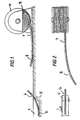
- Figure 1 is a side view of a site with one pipe length already in a trench and another length being unwound from the coiler,
- Figure 2 is an aerial view of Figure 1 with the curved end of the coiled pipe length lying parallel to the ground,
- Figure 3 is an aerial view similar to Figure 2 with a pipe clamp secured to the coiled pipe length and connected to a hoisting apparatus in the form of a mechanical excavator,
- Figure 4 is a side view similar to Figure 1 with the coiled pipe length lifted and rotated 90° from its position in Figure 2 so that the pipe end is now downwardly curving,
- Figure 5 is an isometric view of the closed pipe clamp secured to a pipe,
- Figure 6 is an end view of the clamp in an open position for securing to a pipe,
- Figure 7 is a view similar to Figure 6 with the pipe now clamped in position,
- Figure 8 is a view of Figure 7 from the bolted side, and
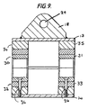
- Figure 9 is a sectional view of the closed clamp showing segments located for different diameters of pipe.
-
- Referring to Figure 1 a trench 1 is dug and in it is located a
first length 2 of previously coiled pipe of approximately 100 metres in length, thelength 2 having been cut from acoil 3 of pipe wound onto the reel, coiler ordrum 4 distanced from thenear end 5 of the trench 1. Thelength 2 of pipe, which is of a suitable plastics material such as polyethylene, is manhandled into the trench 1 and a near end 6 of the length 2 (with respect to the reel 4) projects from thenear end 5 of the trench with an upwardly directed curve to terminate above ground level. As previously explained the curve is caused because the pipe is stored as a coil on thereel 4. - A
second length 7 of pipe is wound from thereel 4 and has anend 8 which also curves in upward direction but opposite to that of thefirst length 2. Under normal conditions, it would be either impossible or extremely difficult to join the twoends 6 and 8 of thelengths length adjacent ends 6 and 8 oflengths - However, referring to Figure 2, in our technique, a
length 7 of pipe is wound from thereel 4 sufficient that itsend 8 lies adjacent thelength 2 and thelength 7 is then allowed to rest on the ground, its weight causing it to rotate about its axis by 90° so that its curve lies parallel to the ground. - Then, referring to Figure 3, a pipe clamp 10 (to be described fully later) is clamped around the
end 8 oflength 7 with the connecting plate 11 of theclamp 10 positioned on the side of thepipe length 7 opposite to the centre of a notional circle which thepipe end 8 would form if its curve continued endlessly. The plate 11 is then connected by a rope orstrop 12 to thebucket 13 of a mechanical excavator (not shown). - Finally, referring to Figure 4, the
excavator bucket 13 is raised to hoist theend 8 oflength 7 so that thepipe end 8 is caused to rotate about its axis by a further 90° as theclamp 10 is itself rotated by thestrop 12. - The
pipe end 8 of thelength 7 now curves in a downward direction and therefore in a substantially opposite sense to the upward curve of the end 6 oflength 2. This enables the two ends to be brought together quite easily and joined by any convenient technique such as butt-fusion welding or the like. - After the
pipe lengths clamp 10 removed. The trench can now be extended rearwardly and a further length of pipe reeled from the coiler, cuts off, and laid in the trench before being joined to a further length of pipe and so on until a pipeline comprising several lengths has been laid. - Referring to Figures 5 to 9, the
pipe clamp 10 is cylindrical and comprises twosemi-circular jaws pipe 7 and which are connected together on one side by ahinge 15, a pair of clamping bolt andnut assemblies jaws plate 18 for releasably connecting the clamp to a hoisting apparatus whereby, in use, the clamp can be raised or lowered to raise and lower the pipe length. - Each
jaw collar members sides jaws shanks respective bolts assemblies - After the pipe has been located in one of the jaws (see Figure 6) when the clamp is in the open position, the jaws are closed together and the
bolts shanks collars jaws purpose nuts respective bolt shank respective collar - Welded to the uppermost (in this embodiment)
jaw 13 of theclamp 10 is aplate 18 located midway between the sides of thejaw 13 which has aneyelet 29 by means of which theplate 18 can be connected to the bucket of a mechanical excavator to lift the clamp and thereby the pipe. - Referring to Figure 9, in order to clamp pipes of differing diameters, the clamp may be provided with internal rings to reduce the diameter of the throat formed by the jaws. As shown there are pairs of
identical rings screw 36 which connects each ring via an aperture to thelowermost jaw 14. - In Figure 9, all the rings are in position so that a pipe of the smallest suitable diameter can be clamped. Removing
rings rings rings
Claims (2)
- A cylindrical pipe clamp (10) comprising two hingeably connected semi-circular member (13,14) which can be brought together around the circumference of a length of pipe (7), means for releasably securing the members together, characterised in that means (18) mounted on one of the members for releasably connecting the clamp (10) to a hoisting apparatus are provided whereby, in use, the clamp (10) can be raised and lowered to raise and lower the pipe length (7) and internal rings (31,32,33,34) to reduce the diameter of the throat formed by the two hingeably connected semi-circular members (13,14) to enable the members to clamp pipes (7) of different external diameters.
- A clamp as claimed in claim 1 in which the means for releasably connecting the clamp to a hoisting apparatus comprises a plate (18) having an eyelet (29) by which the clamp (10) can be releasably tied in use to the hoisting apparatus by means of a strop.
Applications Claiming Priority (3)
| Application Number | Priority Date | Filing Date | Title |
|---|---|---|---|
| GB9604610 | 1996-03-04 | ||
| GB9604610A GB2310906B (en) | 1996-03-04 | 1996-03-04 | Improvements in permitting two adjacent pipe lengths to be joined together |
| EP97103094A EP0794374B1 (en) | 1996-03-04 | 1997-02-26 | Method of joining two adjacent pipe lengths |
Related Parent Applications (1)
| Application Number | Title | Priority Date | Filing Date |
|---|---|---|---|
| EP97103094A Division EP0794374B1 (en) | 1996-03-04 | 1997-02-26 | Method of joining two adjacent pipe lengths |
Publications (3)
| Publication Number | Publication Date |
|---|---|
| EP1054201A2 EP1054201A2 (en) | 2000-11-22 |
| EP1054201A3 EP1054201A3 (en) | 2000-12-13 |
| EP1054201B1 true EP1054201B1 (en) | 2002-12-04 |
Family
ID=10789838
Family Applications (2)
| Application Number | Title | Priority Date | Filing Date |
|---|---|---|---|
| EP97103094A Expired - Lifetime EP0794374B1 (en) | 1996-03-04 | 1997-02-26 | Method of joining two adjacent pipe lengths |
| EP00113142A Expired - Lifetime EP1054201B1 (en) | 1996-03-04 | 1997-02-26 | Pipe clamp |
Family Applications Before (1)
| Application Number | Title | Priority Date | Filing Date |
|---|---|---|---|
| EP97103094A Expired - Lifetime EP0794374B1 (en) | 1996-03-04 | 1997-02-26 | Method of joining two adjacent pipe lengths |
Country Status (5)
| Country | Link |
|---|---|
| US (2) | US5967698A (en) |
| EP (2) | EP0794374B1 (en) |
| DE (2) | DE69717685T2 (en) |
| ES (2) | ES2188450T3 (en) |
| GB (3) | GB2310906B (en) |
Families Citing this family (16)
| Publication number | Priority date | Publication date | Assignee | Title |
|---|---|---|---|---|
| FR2768362B1 (en) * | 1997-09-16 | 2002-09-06 | Puls Action | PROCESS AND DEVICE FOR STRAIGHTENING A LONGILINE ELEMENT AND POSITIONING IN THE SPACE OF THE FREE END OF THIS ELEMENT IN RELATION TO THE FREE END OF AT LEAST ONE OTHER ELEMENT FOR THEIR ASSEMBLY |
| US20030108391A1 (en) * | 2001-12-12 | 2003-06-12 | Lee Essay | Passive irrigation pipe installation reel stand |
| US7226434B2 (en) | 2003-10-31 | 2007-06-05 | Tyco Healthcare Group Lp | Safety shield |
| US7988664B2 (en) | 2004-11-01 | 2011-08-02 | Tyco Healthcare Group Lp | Locking clip with trigger bushing |
| US8747387B2 (en) | 2005-10-11 | 2014-06-10 | Covidien Lp | IV catheter with in-line valve and methods related thereto |
| GB0701223D0 (en) | 2007-01-22 | 2007-02-28 | Airbus Uk Ltd | Cable routing clip |
| WO2009042874A1 (en) | 2007-09-27 | 2009-04-02 | Tyco Healthcare Group Lp | I.v. catheter assembly and needle safety device |
| ATE482738T1 (en) | 2007-12-20 | 2010-10-15 | Tyco Healthcare | CAP ASSEMBLY WITH SPRING-LOADED CUFF |
| US8727024B2 (en) * | 2009-02-13 | 2014-05-20 | Board Of Regents Of The Nevada System Of Higher Education, On Behalf Of The Desert Research Institute | Sampling system and method |
| US20150072081A1 (en) * | 2013-09-10 | 2015-03-12 | Ryan Winston MONCHAMP | External coating method and apparatus |
| EP2539617A1 (en) * | 2010-02-23 | 2013-01-02 | Christopher Charles Macey | Pipe clamp |
| US9851025B2 (en) * | 2015-09-21 | 2017-12-26 | Syncrude Canada Ltd. In Trust For The Owners Of The Syncrude Project As Such Owners Exist Now And In The Future | Polymer-lined pipes and fittings with replaceable components |
| US10139019B2 (en) * | 2015-09-21 | 2018-11-27 | Syncrude Canada Ltd. | Polymer-lined pipes and fittings with replaceable components |
| US9719611B1 (en) | 2016-01-29 | 2017-08-01 | Borehead, Llc | Underground pipe pulling process and pipe pull head |
| CA2978207A1 (en) | 2016-08-31 | 2018-02-28 | Ellingson Companies | Pullhead device and method for use |
| US10844587B2 (en) | 2017-09-26 | 2020-11-24 | Christopher Lombardo | System for stormwater discharge |
Family Cites Families (46)
| Publication number | Priority date | Publication date | Assignee | Title |
|---|---|---|---|---|
| US955342A (en) * | 1909-06-14 | 1910-04-19 | Walter H Maxwell | Pendent sprayer-support. |
| US1558878A (en) * | 1923-02-10 | 1925-10-27 | James E Hitchcock | Safety attachment for rotary hose |
| US1671706A (en) * | 1925-03-21 | 1928-05-29 | Evans William Hooper | Reenforcement for fabric hose |
| US2700988A (en) * | 1951-06-27 | 1955-02-01 | Aeroquip Corp | Hose fitting |
| GB822025A (en) * | 1956-02-25 | 1959-10-21 | Talbot Stead Tube Company Ltd | Pipe coupling |
| US3165286A (en) * | 1961-05-24 | 1965-01-12 | Hewitt Robins Inc | Hinged saddle for hose |
| US3428092A (en) * | 1966-11-02 | 1969-02-18 | Hewitt Robins Inc | Marine hose connector and spacer device |
| US3424415A (en) * | 1967-02-03 | 1969-01-28 | Illinois Railway Equipment Co | Chain locks and chain detachable therefrom for supporting a railway car air brake hose |
| US3540762A (en) * | 1968-08-16 | 1970-11-17 | Jerald V Dunlap | Segmented thread coupling |
| GB1299371A (en) * | 1969-01-15 | 1972-12-13 | Q V F Ltd | Improvements in and relating to clamping devices |
| US3598430A (en) * | 1969-07-24 | 1971-08-10 | Hurricane Pipe Mfg Inc | Pipe connector |
| US3769836A (en) * | 1972-03-09 | 1973-11-06 | Heldies Portable Pipe Service | Apparatus for straightening, untwisting and testing tubular elements |
| AU6148173A (en) * | 1972-10-27 | 1975-04-17 | Johns-Manville Corporation | Plastic pipe thrust resistant joint |
| US3838712A (en) * | 1972-11-30 | 1974-10-01 | Bendix Corp | Structural fitting for filament composite tubular member |
| US3938234A (en) * | 1974-07-15 | 1976-02-17 | George Price | Pipe joining method |
| SE7603676L (en) * | 1976-03-26 | 1977-09-27 | Oberg Karl Erik | METHODS AND SYSTEMS FOR MANUFACTURE AND LAYING OF OIL OR GAS PIPES PIPE ON THE SEA BOTTOM |
| US4113286A (en) * | 1976-09-17 | 1978-09-12 | United States Pipe And Foundry Company | Hanger for pipe |
| US4039087A (en) * | 1976-11-17 | 1977-08-02 | Sandvick Robert M Sen | Pipe laying apparatus |
| US4157023A (en) * | 1977-10-14 | 1979-06-05 | Martech International, Inc. | Apparatus and method for laying pipelines |
| DE2806386A1 (en) * | 1978-02-15 | 1979-08-23 | Hilti Ag | PIPE CLAMP |
| GB2051279B (en) * | 1979-06-15 | 1983-08-10 | Plessey Co Ltd | Couplings |
| DE3044008C1 (en) * | 1980-11-20 | 1982-06-03 | Hubert 1000 Berlin Combé | Pipe clamp |
| US4445255A (en) * | 1982-05-19 | 1984-05-01 | Koomey, Inc. | Hose clamp for supporting a vertically extending control line |
| EP0102161B1 (en) * | 1982-08-18 | 1987-05-20 | Imperial Chemical Industries Plc | Coupling |
| US4521042A (en) * | 1983-07-05 | 1985-06-04 | Hydril Company | Threaded connection |
| FR2563607B1 (en) * | 1984-04-27 | 1986-09-05 | Novatome | ANTI-VIBRATORY SUPPORT DEVICE FOR PIPING WITH A LOW THICKNESS IN RELATION TO THE DIAMETER |
| FR2587272B1 (en) * | 1985-09-19 | 1988-04-15 | Gaz De France | METHOD AND DEVICE FOR STRAIGHTENING AND ALIGNING A FIRST PIECE IN PLASTIC MATERIAL FOR EXAMPLE THERMOSOUDABLE WITH A SECOND PIECE IN SIMILAR PLASTIC MATERIAL WHICH CAN ALSO BE STRAIGHTENED FOR THEIR END-TO-END ASSEMBLY |
| US4647715A (en) * | 1986-01-24 | 1987-03-03 | Butler David O | Aerial communication cable closure |
| US4890957A (en) * | 1986-02-18 | 1990-01-02 | Rinas David E | Cable laying apparatus |
| GB8612383D0 (en) * | 1986-02-21 | 1986-06-25 | Advotec Inc | Pipe handling apparatus |
| DE3622965C1 (en) * | 1986-07-09 | 1987-11-05 | Zueblin Ag | Prefabricated pipe or pipe ring |
| DE8806645U1 (en) * | 1988-05-20 | 1989-09-14 | Lisega Kraftwerkstechnik GmbH, 2730 Zeven | Support bearings for pipes of piping systems |
| GB8826149D0 (en) * | 1988-11-08 | 1988-12-14 | Advanced Mechanics & Eng Ltd | Method for installing pipelines on seabed using reel in conjunction with launch guide stinger |
| US4906131A (en) * | 1989-06-26 | 1990-03-06 | George Savoka | Method for installing sprinkler heads |
| GB2252386B (en) * | 1991-02-01 | 1994-11-30 | North West Water Ltd | Improvements in pipe handling |
| GB2254393A (en) * | 1991-04-03 | 1992-10-07 | Advanced Mechanics & Engineeri | Reeling systems for undersea pipe |
| FR2678530B1 (en) * | 1991-07-05 | 1993-10-29 | Sauron Materiel Indl Joseph | PORTABLE TUBE STRAIGHTENING APPARATUS. |
| DE4123430C1 (en) * | 1991-07-15 | 1992-06-17 | Trw United-Carr Gmbh & Co Kg, 6753 Enkenbach-Alsenborn, De | |
| US5136757A (en) * | 1991-08-13 | 1992-08-11 | Armand Labonville | Releasable and adjustable fire hose clamp |
| DE9204390U1 (en) * | 1992-03-31 | 1992-07-30 | Lisega GmbH, 2730 Zeven | Pipe clamp |
| FR2703707B1 (en) * | 1993-04-08 | 1995-09-29 | Pirelli Cables | Method for laying a product of great length in the ground, and devices for its implementation. |
| US5413063A (en) * | 1994-01-21 | 1995-05-09 | King; William E. | Rail fitting for marine applications |
| GB9412538D0 (en) * | 1994-06-22 | 1994-08-10 | North West Water Group Plc | Reverse pipe bending |
| US5641246A (en) * | 1995-02-06 | 1997-06-24 | Rinas; David Edward | Cable laying apparatus |
| JP3422452B2 (en) * | 1995-12-08 | 2003-06-30 | テルモ株式会社 | Tube connection device |
| US5853030A (en) * | 1997-03-11 | 1998-12-29 | Walding; Larry | Pipe coupling with a disinfectant injection port |
-
1996
- 1996-03-04 GB GB9604610A patent/GB2310906B/en not_active Revoked
- 1996-03-04 GB GB9917358A patent/GB2337312A/en not_active Withdrawn
- 1996-03-04 GB GB9917357A patent/GB2337095B/en not_active Expired - Fee Related
-
1997
- 1997-02-26 EP EP97103094A patent/EP0794374B1/en not_active Expired - Lifetime
- 1997-02-26 ES ES00113142T patent/ES2188450T3/en not_active Expired - Lifetime
- 1997-02-26 EP EP00113142A patent/EP1054201B1/en not_active Expired - Lifetime
- 1997-02-26 DE DE69717685T patent/DE69717685T2/en not_active Expired - Fee Related
- 1997-02-26 ES ES97103094T patent/ES2180833T3/en not_active Expired - Lifetime
- 1997-02-26 DE DE69714319T patent/DE69714319T2/en not_active Expired - Fee Related
- 1997-03-04 US US08/811,020 patent/US5967698A/en not_active Expired - Fee Related
-
1999
- 1999-02-17 US US09/250,610 patent/US6148864A/en not_active Expired - Fee Related
Also Published As
| Publication number | Publication date |
|---|---|
| EP0794374A1 (en) | 1997-09-10 |
| GB9917357D0 (en) | 1999-09-22 |
| US5967698A (en) | 1999-10-19 |
| DE69717685T2 (en) | 2003-10-02 |
| EP1054201A2 (en) | 2000-11-22 |
| GB2310906B (en) | 2000-05-03 |
| ES2180833T3 (en) | 2003-02-16 |
| US6148864A (en) | 2000-11-21 |
| GB9604610D0 (en) | 1996-05-01 |
| GB2337095A (en) | 1999-11-10 |
| DE69714319T2 (en) | 2003-03-20 |
| DE69714319D1 (en) | 2002-09-05 |
| EP1054201A3 (en) | 2000-12-13 |
| GB2337095B (en) | 2000-05-03 |
| ES2188450T3 (en) | 2003-07-01 |
| GB2310906A (en) | 1997-09-10 |
| GB2337312A (en) | 1999-11-17 |
| DE69717685D1 (en) | 2003-01-16 |
| EP0794374B1 (en) | 2002-07-31 |
| GB9917358D0 (en) | 1999-09-22 |
Similar Documents
| Publication | Publication Date | Title |
|---|---|---|
| US5967698A (en) | Permitting two adjacent pipe lengths to be joined together | |
| CA2188102C (en) | Pipe rehabilitation system and methods | |
| US7490814B2 (en) | Cable pulling machine | |
| US11619336B2 (en) | Pipe slitting machine with rope storage reel | |
| US12126149B2 (en) | Cable puller and method of use | |
| NL9400517A (en) | Method and device for laying a pipeline on an underwater ground. | |
| US7128499B2 (en) | Method for extracting underground pipe | |
| US4538937A (en) | Marine continuous pipe laying system | |
| BR112012020150B1 (en) | METHOD FOR LAYING A HYBRID PIPELINE | |
| US8336937B2 (en) | Pipe pile sling | |
| EP2689173B1 (en) | Abandon / recovery method for pipelines and apparatus therefor | |
| CN113639098B (en) | Krah pipe socket joint electric melting connection structure and construction method thereof | |
| CN221118529U (en) | Cross-sea bridge cofferdam installation device | |
| US6830235B2 (en) | Hydraulic powered capstan attachment | |
| CN113373922B (en) | Geothermal energy pile construction equipment and construction method thereof | |
| US10132102B2 (en) | Adapter device | |
| CN117071615A (en) | A cross-sea bridge cofferdam installation device and its construction method | |
| US11434706B1 (en) | Pipe handling assembly for use in horizontal directional drilling | |
| JP2026060138A (en) | PC steel wire insertion device for shield tunneling. | |
| EP0963798A1 (en) | Pipe-bending machine suitable for operating on the seabed | |
| GB1592455A (en) | Methods of installing an outer pipe on an existing pipeline | |
| JPH053591Y2 (en) | ||
| JP2004169428A (en) | Downhole drilling system controller | |
| JPH0710456A (en) | Method of suspending a plurality of pipe members, and clampers used therefor | |
| JPH0736661B2 (en) | Guidance device |
Legal Events
| Date | Code | Title | Description |
|---|---|---|---|
| PUAI | Public reference made under article 153(3) epc to a published international application that has entered the european phase |
Free format text: ORIGINAL CODE: 0009012 |
|
| PUAL | Search report despatched |
Free format text: ORIGINAL CODE: 0009013 |
|
| AC | Divisional application: reference to earlier application |
Ref document number: 794374 Country of ref document: EP |
|
| AK | Designated contracting states |
Kind code of ref document: A2 Designated state(s): BE DE ES FR GB IT NL SE |
|
| AK | Designated contracting states |
Kind code of ref document: A3 Designated state(s): BE DE ES FR GB IT NL SE |
|
| RIC1 | Information provided on ipc code assigned before grant |
Free format text: 7F 16L 1/20 A, 7F 16L 1/028 B, 7F 16L 1/06 B |
|
| 17P | Request for examination filed |
Effective date: 20010102 |
|
| AKX | Designation fees paid |
Free format text: BE DE ES FR GB IT NL SE |
|
| RAP1 | Party data changed (applicant data changed or rights of an application transferred) |
Owner name: LATTICE INTELLECTUAL PROPERTY LIMITED |
|
| GRAG | Despatch of communication of intention to grant |
Free format text: ORIGINAL CODE: EPIDOS AGRA |
|
| RTI1 | Title (correction) |
Free format text: PIPE CLAMP |
|
| RTI1 | Title (correction) |
Free format text: PIPE CLAMP |
|
| 17Q | First examination report despatched |
Effective date: 20020225 |
|
| GRAG | Despatch of communication of intention to grant |
Free format text: ORIGINAL CODE: EPIDOS AGRA |
|
| GRAG | Despatch of communication of intention to grant |
Free format text: ORIGINAL CODE: EPIDOS AGRA |
|
| GRAH | Despatch of communication of intention to grant a patent |
Free format text: ORIGINAL CODE: EPIDOS IGRA |
|
| GRAH | Despatch of communication of intention to grant a patent |
Free format text: ORIGINAL CODE: EPIDOS IGRA |
|
| GRAA | (expected) grant |
Free format text: ORIGINAL CODE: 0009210 |
|
| AC | Divisional application: reference to earlier application |
Ref document number: 794374 Country of ref document: EP |
|
| AK | Designated contracting states |
Kind code of ref document: B1 Designated state(s): BE DE ES FR GB IT NL SE |
|
| PG25 | Lapsed in a contracting state [announced via postgrant information from national office to epo] |
Ref country code: NL Free format text: LAPSE BECAUSE OF FAILURE TO SUBMIT A TRANSLATION OF THE DESCRIPTION OR TO PAY THE FEE WITHIN THE PRESCRIBED TIME-LIMIT Effective date: 20021204 |
|
| REG | Reference to a national code |
Ref country code: GB Ref legal event code: FG4D |
|
| PGFP | Annual fee paid to national office [announced via postgrant information from national office to epo] |
Ref country code: FR Payment date: 20030113 Year of fee payment: 7 |
|
| PGFP | Annual fee paid to national office [announced via postgrant information from national office to epo] |
Ref country code: GB Payment date: 20030116 Year of fee payment: 7 |
|
| REF | Corresponds to: |
Ref document number: 69717685 Country of ref document: DE Date of ref document: 20030116 |
|
| PGFP | Annual fee paid to national office [announced via postgrant information from national office to epo] |
Ref country code: SE Payment date: 20030120 Year of fee payment: 7 Ref country code: NL Payment date: 20030120 Year of fee payment: 7 Ref country code: DE Payment date: 20030120 Year of fee payment: 7 |
|
| PGFP | Annual fee paid to national office [announced via postgrant information from national office to epo] |
Ref country code: BE Payment date: 20030203 Year of fee payment: 7 |
|
| PGFP | Annual fee paid to national office [announced via postgrant information from national office to epo] |
Ref country code: ES Payment date: 20030210 Year of fee payment: 7 |
|
| ET | Fr: translation filed | ||
| NLV1 | Nl: lapsed or annulled due to failure to fulfill the requirements of art. 29p and 29m of the patents act | ||
| REG | Reference to a national code |
Ref country code: ES Ref legal event code: FG2A Ref document number: 2188450 Country of ref document: ES Kind code of ref document: T3 |
|
| PLBE | No opposition filed within time limit |
Free format text: ORIGINAL CODE: 0009261 |
|
| STAA | Information on the status of an ep patent application or granted ep patent |
Free format text: STATUS: NO OPPOSITION FILED WITHIN TIME LIMIT |
|
| 26N | No opposition filed |
Effective date: 20030905 |
|
| PG25 | Lapsed in a contracting state [announced via postgrant information from national office to epo] |
Ref country code: GB Free format text: LAPSE BECAUSE OF NON-PAYMENT OF DUE FEES Effective date: 20040226 |
|
| PG25 | Lapsed in a contracting state [announced via postgrant information from national office to epo] |
Ref country code: SE Free format text: LAPSE BECAUSE OF NON-PAYMENT OF DUE FEES Effective date: 20040227 Ref country code: ES Free format text: LAPSE BECAUSE OF NON-PAYMENT OF DUE FEES Effective date: 20040227 |
|
| PG25 | Lapsed in a contracting state [announced via postgrant information from national office to epo] |
Ref country code: BE Free format text: LAPSE BECAUSE OF NON-PAYMENT OF DUE FEES Effective date: 20040228 |
|
| BERE | Be: lapsed |
Owner name: *LATTICE INTELLECTUAL PROPERTY LTD Effective date: 20040228 |
|
| PG25 | Lapsed in a contracting state [announced via postgrant information from national office to epo] |
Ref country code: DE Free format text: LAPSE BECAUSE OF NON-PAYMENT OF DUE FEES Effective date: 20040901 |
|
| EUG | Se: european patent has lapsed | ||
| GBPC | Gb: european patent ceased through non-payment of renewal fee |
Effective date: 20040226 |
|
| PG25 | Lapsed in a contracting state [announced via postgrant information from national office to epo] |
Ref country code: FR Free format text: LAPSE BECAUSE OF NON-PAYMENT OF DUE FEES Effective date: 20041029 |
|
| REG | Reference to a national code |
Ref country code: FR Ref legal event code: ST |
|
| PG25 | Lapsed in a contracting state [announced via postgrant information from national office to epo] |
Ref country code: IT Free format text: LAPSE BECAUSE OF NON-PAYMENT OF DUE FEES Effective date: 20050226 |
|
| REG | Reference to a national code |
Ref country code: ES Ref legal event code: FD2A Effective date: 20040227 |