EP1054106A2 - Box girder structure for bridge provided with outer cable and method of building the box girder - Google Patents
Box girder structure for bridge provided with outer cable and method of building the box girder Download PDFInfo
- Publication number
- EP1054106A2 EP1054106A2 EP00110193A EP00110193A EP1054106A2 EP 1054106 A2 EP1054106 A2 EP 1054106A2 EP 00110193 A EP00110193 A EP 00110193A EP 00110193 A EP00110193 A EP 00110193A EP 1054106 A2 EP1054106 A2 EP 1054106A2
- Authority
- EP
- European Patent Office
- Prior art keywords
- sheath
- box girder
- grout
- transparent
- cable
- Prior art date
- Legal status (The legal status is an assumption and is not a legal conclusion. Google has not performed a legal analysis and makes no representation as to the accuracy of the status listed.)
- Withdrawn
Links
- 238000000034 method Methods 0.000 title claims description 22
- 239000011440 grout Substances 0.000 claims abstract description 79
- 238000002347 injection Methods 0.000 claims abstract description 15
- 239000007924 injection Substances 0.000 claims abstract description 15
- 229920005989 resin Polymers 0.000 claims abstract description 14
- 239000011347 resin Substances 0.000 claims abstract description 14
- -1 polypropylene Polymers 0.000 claims abstract description 12
- BZHJMEDXRYGGRV-UHFFFAOYSA-N Vinyl chloride Chemical compound ClC=C BZHJMEDXRYGGRV-UHFFFAOYSA-N 0.000 claims abstract description 8
- 239000004743 Polypropylene Substances 0.000 claims abstract description 4
- 229920013716 polyethylene resin Polymers 0.000 claims abstract description 4
- 229920001155 polypropylene Polymers 0.000 claims abstract description 4
- 229910000831 Steel Inorganic materials 0.000 claims description 37
- 239000010959 steel Substances 0.000 claims description 37
- 239000000463 material Substances 0.000 claims description 28
- 210000002435 tendon Anatomy 0.000 claims description 21
- 239000004567 concrete Substances 0.000 claims description 20
- 238000007689 inspection Methods 0.000 claims description 13
- 239000004698 Polyethylene Substances 0.000 claims description 8
- 229920000573 polyethylene Polymers 0.000 claims description 8
- 230000000007 visual effect Effects 0.000 claims description 7
- 239000004809 Teflon Substances 0.000 claims description 3
- 229920006362 Teflon® Polymers 0.000 claims description 3
- 239000002131 composite material Substances 0.000 claims description 3
- 229920005668 polycarbonate resin Polymers 0.000 claims description 3
- 239000004431 polycarbonate resin Substances 0.000 claims description 3
- 239000011800 void material Substances 0.000 abstract 1
- 230000009467 reduction Effects 0.000 description 8
- 238000010276 construction Methods 0.000 description 5
- 238000005260 corrosion Methods 0.000 description 5
- 239000004568 cement Substances 0.000 description 4
- 239000008267 milk Substances 0.000 description 4
- 210000004080 milk Anatomy 0.000 description 4
- 235000013336 milk Nutrition 0.000 description 4
- 230000008859 change Effects 0.000 description 3
- 238000012790 confirmation Methods 0.000 description 3
- 238000007796 conventional method Methods 0.000 description 3
- 230000000694 effects Effects 0.000 description 3
- 238000012423 maintenance Methods 0.000 description 3
- 238000012986 modification Methods 0.000 description 3
- 230000004048 modification Effects 0.000 description 3
- 239000011513 prestressed concrete Substances 0.000 description 3
- UQSXHKLRYXJYBZ-UHFFFAOYSA-N Iron oxide Chemical compound [Fe]=O UQSXHKLRYXJYBZ-UHFFFAOYSA-N 0.000 description 2
- 230000005540 biological transmission Effects 0.000 description 2
- 238000004040 coloring Methods 0.000 description 2
- 238000002474 experimental method Methods 0.000 description 2
- AMWRITDGCCNYAT-UHFFFAOYSA-L hydroxy(oxo)manganese;manganese Chemical compound [Mn].O[Mn]=O.O[Mn]=O AMWRITDGCCNYAT-UHFFFAOYSA-L 0.000 description 2
- 230000008439 repair process Effects 0.000 description 2
- 238000012360 testing method Methods 0.000 description 2
- 229920000049 Carbon (fiber) Polymers 0.000 description 1
- QPLDLSVMHZLSFG-UHFFFAOYSA-N Copper oxide Chemical compound [Cu]=O QPLDLSVMHZLSFG-UHFFFAOYSA-N 0.000 description 1
- 239000005751 Copper oxide Substances 0.000 description 1
- 229920002430 Fibre-reinforced plastic Polymers 0.000 description 1
- 239000011398 Portland cement Substances 0.000 description 1
- WGLPBDUCMAPZCE-UHFFFAOYSA-N Trioxochromium Chemical compound O=[Cr](=O)=O WGLPBDUCMAPZCE-UHFFFAOYSA-N 0.000 description 1
- 230000005856 abnormality Effects 0.000 description 1
- 230000004075 alteration Effects 0.000 description 1
- 238000004873 anchoring Methods 0.000 description 1
- 238000005452 bending Methods 0.000 description 1
- 239000006229 carbon black Substances 0.000 description 1
- 239000004917 carbon fiber Substances 0.000 description 1
- 229910000423 chromium oxide Inorganic materials 0.000 description 1
- 239000000470 constituent Substances 0.000 description 1
- 229910000431 copper oxide Inorganic materials 0.000 description 1
- 230000007797 corrosion Effects 0.000 description 1
- 238000005336 cracking Methods 0.000 description 1
- 238000013461 design Methods 0.000 description 1
- 238000005516 engineering process Methods 0.000 description 1
- 230000002708 enhancing effect Effects 0.000 description 1
- 239000011151 fibre-reinforced plastic Substances 0.000 description 1
- 239000000945 filler Substances 0.000 description 1
- VNWKTOKETHGBQD-UHFFFAOYSA-N methane Chemical compound C VNWKTOKETHGBQD-UHFFFAOYSA-N 0.000 description 1
- 230000019612 pigmentation Effects 0.000 description 1
- 230000008569 process Effects 0.000 description 1
- 230000000644 propagated effect Effects 0.000 description 1
- 239000012783 reinforcing fiber Substances 0.000 description 1
- 125000006850 spacer group Chemical group 0.000 description 1
- 239000000126 substance Substances 0.000 description 1
- 239000012780 transparent material Substances 0.000 description 1
- XLYOFNOQVPJJNP-UHFFFAOYSA-N water Substances O XLYOFNOQVPJJNP-UHFFFAOYSA-N 0.000 description 1
Images



Classifications
-
- E—FIXED CONSTRUCTIONS
- E01—CONSTRUCTION OF ROADS, RAILWAYS, OR BRIDGES
- E01D—CONSTRUCTION OF BRIDGES, ELEVATED ROADWAYS OR VIADUCTS; ASSEMBLY OF BRIDGES
- E01D2/00—Bridges characterised by the cross-section of their bearing spanning structure
- E01D2/04—Bridges characterised by the cross-section of their bearing spanning structure of the box-girder type
-
- E—FIXED CONSTRUCTIONS
- E01—CONSTRUCTION OF ROADS, RAILWAYS, OR BRIDGES
- E01D—CONSTRUCTION OF BRIDGES, ELEVATED ROADWAYS OR VIADUCTS; ASSEMBLY OF BRIDGES
- E01D19/00—Structural or constructional details of bridges
- E01D19/16—Suspension cables; Cable clamps for suspension cables ; Pre- or post-stressed cables
-
- E—FIXED CONSTRUCTIONS
- E04—BUILDING
- E04C—STRUCTURAL ELEMENTS; BUILDING MATERIALS
- E04C5/00—Reinforcing elements, e.g. for concrete; Auxiliary elements therefor
- E04C5/08—Members specially adapted to be used in prestressed constructions
- E04C5/10—Ducts
-
- E—FIXED CONSTRUCTIONS
- E01—CONSTRUCTION OF ROADS, RAILWAYS, OR BRIDGES
- E01D—CONSTRUCTION OF BRIDGES, ELEVATED ROADWAYS OR VIADUCTS; ASSEMBLY OF BRIDGES
- E01D2101/00—Material constitution of bridges
- E01D2101/20—Concrete, stone or stone-like material
- E01D2101/24—Concrete
- E01D2101/26—Concrete reinforced
- E01D2101/28—Concrete reinforced prestressed
Definitions
- the present invention relates to a box girder structure for a bridge provided with outer cables and also relates to a method of building the box girder. More particularly, the present invention relates to a box girder structure including outer cables used to a prestressed concrete box girder of a bridge, the outer cables being improved so that grout can be fully filled in the sheaths of the outer cables surely and easily. The present invention also relates to a method of building the box girder.
- Prestressed-concrete structures built by the post-tensioning system include an inner-cable structure in which tendons, e.g. prestressing steel wires or steel strands, covered with sheaths are provided within a concrete member.
- tendons e.g. prestressing steel wires or steel strands
- sheaths are provided within a concrete member.
- an "outer-cable structure" has been adopted to reduce the wall thickness of box girder members, in which prestressing tendons are provided out of the concrete members in cross-section of the girder (i.e. in the space inside the box girder cross-section).
- the use of the outer-cable structure allows the box girder itself to be reduced in weight and also permits a reduction in material cost and a reduction in work volume required for construction, plus enabling the maintenance and repair of prestressing cables, advantageously.
- the reduction in weight of the superstructure leads to a reduction in cost of the substructure (the foundation and piers of a bridge) supporting the superstructure.
- a prestressing tendon that is made up of a large number of prestressing steel wires or steel strands is inserted into a sheath to form an outer cable.
- tensile stress is applied to the tendon at anchorages provided at both ends of the box girder through anchoring devices to induce compressive stress (prestress) in the concrete girder, thereby improving the load-carrying capacity of the whole box girder.
- a steel pipe or a black polyethylene pipe is generally used as a sheath from the viewpoint of durability.
- the black polyethylene pipe is formed by mixing an ordinary polyethylene component with carbon black or the like to blacken the polyethylene pipe for the purpose of preventing the material from being deteriorated by ultraviolet exposure.
- tendons which are made of steel, must be subjected to anti-corrosion treatment because of its property.
- anti-corrosion treatment for the tendon in the sheath of each outer cable installed in a box girder at a bridge construction site, cement milk or a resin- or oil-based filler is injected into vacant spaces in the sheath as a grout.
- cement milk is a strongly alkaline inorganic grout. Therefore, if cement milk is satisfactorily filled to enclose prestressing steel or the like, which is sensitive to stress corrosion, best durability is exhibited, and high reliability is obtained.
- a grout is injected into the sheath by a grout pump from a grout injection hole provided in the anchorage at one end of the sheath, and it is judged that filling of the grout has been completed when the grout has reached the anchorage at the other end of the sheath.
- the filling condition of the grout injected into the sheath can be confirmed only indirectly by making a visual check as to whether or not excess grout has been discharged from the upper ends of discharge hoses provided at several positions in an intermediate portion of the sheath.
- the object in injecting a grout into the sheath of an outer cable is to fill vacant spaces in the sheath with a homogeneous grout and to enclose a tendon made of prestressing steel or the like satisfactorily, thereby taking anti-corrosion measures. That is, in the grout injection operation, reliable and elaborate filling is important. In the conventional method, however, a black polyethylene pipe or a steel pipe is used as a sheath pipe, and it is therefore difficult to inspect or confirm the filling condition of the grout either during or after the grouting operation. In particular, the filling condition of the grout cannot readily be confirmed or inspected by visual observation. Accordingly, the conventional method suffers from serious problems in terms of reliability and so forth.
- outer cables are designed so that they are not only disposed in parallel longitudinally in a box girder but also caused to change in direction vertically by deflectors provided in the box girder. This is done to prestress the box girder not only in the longitudinal direction but also in the vertical direction so as to cope with various stresses induced in the whole concrete structure.
- size of a tendon has been increased so as to reduce costs of labor relative to post-tensioning operation including pre and post works such as placing ducts and injecting grout.
- the use of outer cables with an increased outer diameter requires a special consideration to be given to the deflector structure.
- outer cable structure is applicable not only to concrete box girders but also to steel box girders.
- An object of the present invention is to provide a technique whereby the filling condition of a grout in the sheath of an outer cable can be observed reliably and easily.
- the present invention provides the following.
- reference numeral 1 denotes a web
- 2 denotes outer cables
- 3 denotes an upper floor slab (flange);
- 4 denotes a lower floor slab (flange);
- 5 denotes deflectors;
- 5' denotes through-holes;
- 6 denotes anchorages;
- 7 denotes a transparent sheath;
- 8 denotes a tendon;
- 9 denotes a grout;
- 10 denotes a grout injection pipe connecting opening;
- 11 denotes a drainage hose connecting opening;
- 71 denotes a spiral crest portion;
- 72 denotes a spiral shallow groove portion (root portion);
- 12 denotes diabolos (curved steel pipes);
- 13 denotes sheath joints; and 100 denotes a box girder.
- the present invention provides a box girder structure including outer cables disposed in a box girder of a box girder bridge to prestress the box girder, wherein each outer cable is disposed in a transparent sheath so that inspection during injection of a grout into the sheath or inspection of the condition in the sheath and refilling of the grout into a vacant space in the sheath can be performed reliably and easily, and also provides a method of building the box girder structure.
- box girder means, as shown in Fig. 1, a beam having a box-shaped cross-section (hollow closed cross-section) 100 formed by upper and lower flanges 3 and 4 and vertical or slant webs 1 joining the flanges 3 and 4.
- box girder 100 include a single-box girder and a multiple-box girder.
- Parts (a), (b) and (c) of Fig. 6 show examples of the sectional configurations of such box girders.
- the present invention is not necessarily limited to the illustrated box girders but may include any bridge structure suitable for disposing outer cables for prestressing.
- box girder bridge means a bridge of the type in which a box girder is supported by abutments or piers.
- the present invention may include any type of bridge that is known to those skilled in the art or readily available, provided that the bridge can use a transparent sheath for an outer cable for prestressing.
- pretressing means previously applying stress to cancel the tensile stress to concrete in a direction opposite to a direction in which tensile stress may be applied to the concrete, that is, previously applying compressive stress (tensioning force of prestressing steel that is introduced into the girder cross-section).
- outer cable means a cable made of steel or the like which is provided to prestress concrete. More specifically, the outer cable is provided out of the concrete member in cross-section of a girder (i.e. in the space inside the box girder cross-section).
- the term "transparent” used in the term “transparent sheath” means, for example, that the filling condition of a grout being filled into the sheath can be visually observed from the outside of the sheath. It is possible to use a sheath having any property as long as it performs the above-described function.
- the term “transparent sheath” may mean a sheath having light transmission properties, for example. Light in this case may mean visible light.
- the term “sheath” means a hollow, typically tubular, or duct member that can pass a prestressing steel in the hollow portion thereof. The sheath performs the function of sheathing the prestressing steel extending through the hollow portion. There is no particular restriction on the shape of the sheath. It is possible to use any type of sheath that is known to those skilled in the art or readily available, provided that the selected sheath can pass a prestressing steel in the hollow portion thereof.
- Fig. 1 is a sectional view of a box girder constituting a bridge
- Fig. 2 is a vertically sectioned perspective view showing a central portion of the box girder, which is partly sectioned in the longitudinal direction.
- Fig. 3 is a vertical sectional view showing various constituent elements present between two anchorages of a single outer cable, in which the distance between the two anchorages is reduced.
- Fig. 4 is a sectional view of a sheath formed into a bellows-shaped member, particularly a bellows-shaped member having a spiral shallow groove, to impart flexibility to the sheath.
- Fig. 5 is a view showing the external appearance of the sheath illustrated in Fig. 4.
- Fig. 4 is a sectional view showing various constituent elements present between two anchorages of a single outer cable, in which the distance between the two anchorages is reduced.
- Fig. 4 is a sectional view of a sheath formed into a bellows-shaped member, particularly a bellows-shaped member having a spiral shallow groove, to impart flexibility to the sheath.
- Fig. 5 is a view showing the external appearance of the sheath illustrated in Fig. 4.
- Fig. 5 is a view showing the external appearance of the she
- part (a) is a sectional view of a single-box girder
- part (b) is a sectional view of a multiple-box girder
- part (c) is a sectional view of another multiple-box girder having a different configuration.
- a large number of outer cables 2 are disposed in the space inside the webs 1 of a box girder 100 constituting a bridge, which is formed from a concrete structure.
- a box girder 100 constituting a bridge, which is formed from a concrete structure.
- An upper floor slab 3 is provided at the top of the box girder to form a road surface on which vehicles will drive.
- Concrete structures constituting deflectors 5 are provided on the side surfaces of the box girder at intervals necessary. The concrete structures are integral with the webs 1.
- Each of the outer cables 2 for prestressing the box girder extends through a through-hole 5' provided in a deflector 5 to change its stretching direction and then passes through a through-hole 5' in another deflector 5 to reach an anchorage 6 at each end of the cable 2 where it is secured.
- the cable deflectors 5 are provided to change the cable stretching direction so as to produce prestressing forces in the vertical direction of the structure through contacting pressures at deflectors.
- a cable used in a box girder for an ordinary bridge includes one or a plurality of prestressing steel wires or steel strands each consisting of a large number of thin steel wires, which are bundled to form a tendon 8.
- the tendon 8 is inserted into a sheath 7. Vacant spaces in the sheath 7 are fully filled with a grout 9. Thus, the cable looks like a thick rope. Tensioning force is applied to the cable at the anchorages 6 provided at both ends of the box girder. The tensioning force is constantly maintained even in actual use to maintain the load-carrying capacity of the concrete structure and to prevent failure due to harmful cracking or the like.
- the transparent sheath 7 is a transparent pipe made of a transparent resin material selected from among a vinyl chloride resin material, a polyethylene resin material, a polypropylene resin material, a polycarbonate resin material, a Teflon resin material and so forth, or a composite material consisting of two or more of these materials, or other transparent materials.
- a transparent resin material selected from among a vinyl chloride resin material, a polyethylene resin material, a polypropylene resin material, a polycarbonate resin material, a Teflon resin material and so forth, or a composite material consisting of two or more of these materials, or other transparent materials.
- a vinyl chloride pipe is suitable from the viewpoint of economy and properties.
- a reeled vinyl chloride pipe of continuous length (about 50 meters at maximum) is unreeled at the site of construction when installed.
- cut lengths of vinyl chloride pipe may be connected together to form the whole length of sheath at the site of construction.
- the sheath transparent and flexible. It is particularly preferable to form the sheath into a bellows-shaped member having a spiral shallow groove as shown in Figs. 4 and 5. By doing so, the sheath is improved in handling properties required in a bending operation and so forth.
- reference numeral 71 denotes a spiral crest portion
- reference numeral 72 denotes a spiral shallow groove portion (root portion).
- the crest portion of the bellows-shaped member, which constitutes the sheath 7 is formed by the spiral crest portion 71, and the root portion of the bellows-shaped member is formed by the spiral shallow groove portion 72. Therefore, as grout is filled into the sheath 7 from one end thereof, air at the inner surface of the sheath pipe wall spirally moves toward the other end along the inner side of the spiral crest portion 71. As a result, no air collects at the inner surface of the sheath pipe wall. Accordingly, the effect of the sheath 7 further improves.
- the tendon 8 constituting the cable it is also possible to use a fiber-reinforced plastic material, which is reinforced with reinforcing fiber, e.g. carbon fiber, in addition to steel.
- a fiber-reinforced plastic material which is reinforced with reinforcing fiber, e.g. carbon fiber
- steel is often used from the viewpoint of economy.
- an appropriate steel material may be selected from those which are widely known to those skilled in the art as prestressing steel or from those developed for use as prestressing steel.
- a plurality of deflectors 5 are provided inside the central portion of the box girder of the bridge.
- a curved steel pipe known as a diabolo 12 is provided in each deflector 5 for each cable.
- the curved steel pipe allows the cable to be brought into surface contact with the sheath 7 forming the outer surface of the cable, thereby reducing frictional resistance and thus allowing the cable to move smoothly during prestressing. It should be noted that an effective way of further reducing the frictional resistance is to form a polyethylene sheet on the surface of the diabolo 12.
- Contacting pressure occurring at the deflector 5 is likely to impose a load locally on sheathing enveloping the tendon 8 in the sheath 7.
- spacers for reducing friction are placed through the curved steel pipe. To reduce cost of material and labor transparent resin sheathing can be cast directly in concrete of the deflector.
- an injection hose is attached to a connecting opening for grouting provided at an endmost portion 10 of the sheath 7 at the anchorage 6.
- cement or resin milk is used as a grout, and it is injected by using a grout pump (with a maximum capacity of about 15 atm pressure, in general).
- An effective way of allowing the sheath to be smoothly exhausted of air during grouting is to provide an exhaust opening in the sheath at a relatively high cable position. The condition of the grout being filled into the sheath 7 can be observed through the transparent sheath 7 at any time.
- a colored grout prepared by mixing a grout with a small amount of an inorganic coloring material, e.g. chromium oxide, iron oxide, copper oxide, or manganese oxide, or an organic coloring material. By doing so, the filling condition of the grout in the transparent sheath can be grasped even more clearly. It is preferable to adjust the degree of pigmentation so that the color of the grout is not very deep but sufficiently noticeable to allow a vacant space to be readily found.
- an inorganic coloring material e.g. chromium oxide, iron oxide, copper oxide, or manganese oxide
- An anchorage for the Anderson method was installed at one end of the sheath, and a water stop jig was installed at the other end of the sheath. Strands (19 strands) were inserted into the sheath. Then, the grout was injected into the sheath, and the process of injection was observed. After a collection of air had been found above deflectors, a discharge hose was opened to remove the air. After the sheath had been injected with the grout, it was possible to check the injected condition over the entire length of the sheath. Further, a colored grout was injected into the sheath. As a result, it became markedly easy to check movement of the grout in the sheath.
- each cable that extends along the lower floor slab of the box girder is likely to be fully filled with the grout because air bubbles getting mixed therein during grouting and vacant spaces produced in the sheath are likely to move upwardly and be replaced by the grout. Therefore, an opaque sheath, which is less costly, can be used for the sheath at this portion.
Landscapes
- Engineering & Computer Science (AREA)
- Architecture (AREA)
- Civil Engineering (AREA)
- Structural Engineering (AREA)
- Bridges Or Land Bridges (AREA)
Abstract
Description
- The present invention relates to a box girder structure for a bridge provided with outer cables and also relates to a method of building the box girder. More particularly, the present invention relates to a box girder structure including outer cables used to a prestressed concrete box girder of a bridge, the outer cables being improved so that grout can be fully filled in the sheaths of the outer cables surely and easily. The present invention also relates to a method of building the box girder.
- Prestressed-concrete structures built by the post-tensioning system include an inner-cable structure in which tendons, e.g. prestressing steel wires or steel strands, covered with sheaths are provided within a concrete member. In such an inner-cable structure, when a grout is filled in the sheaths after prestressing has been done, it is extremely difficult to detect the filling condition of the grout.
- In compliance with the demand for a reduction in weight of prestressed-concrete box girders, an "outer-cable structure" has been adopted to reduce the wall thickness of box girder members, in which prestressing tendons are provided out of the concrete members in cross-section of the girder (i.e. in the space inside the box girder cross-section).
- The use of the outer-cable structure allows the box girder itself to be reduced in weight and also permits a reduction in material cost and a reduction in work volume required for construction, plus enabling the maintenance and repair of prestressing cables, advantageously. In addition, the reduction in weight of the superstructure leads to a reduction in cost of the substructure (the foundation and piers of a bridge) supporting the superstructure.
- In the outer-cable structure, a prestressing tendon that is made up of a large number of prestressing steel wires or steel strands is inserted into a sheath to form an outer cable.
- As in the case of the inner-cable structure, tensile stress is applied to the tendon at anchorages provided at both ends of the box girder through anchoring devices to induce compressive stress (prestress) in the concrete girder, thereby improving the load-carrying capacity of the whole box girder.
- In the outer cable, a steel pipe or a black polyethylene pipe is generally used as a sheath from the viewpoint of durability. The black polyethylene pipe is formed by mixing an ordinary polyethylene component with carbon black or the like to blacken the polyethylene pipe for the purpose of preventing the material from being deteriorated by ultraviolet exposure.
- Incidentally, tendons, which are made of steel, must be subjected to anti-corrosion treatment because of its property. To carry out anti-corrosion treatment for the tendon in the sheath of each outer cable installed in a box girder at a bridge construction site, cement milk or a resin- or oil-based filler is injected into vacant spaces in the sheath as a grout.
- Above all, cement milk is a strongly alkaline inorganic grout. Therefore, if cement milk is satisfactorily filled to enclose prestressing steel or the like, which is sensitive to stress corrosion, best durability is exhibited, and high reliability is obtained.
- In general, a grout is injected into the sheath by a grout pump from a grout injection hole provided in the anchorage at one end of the sheath, and it is judged that filling of the grout has been completed when the grout has reached the anchorage at the other end of the sheath.
- On this occasion, the filling condition of the grout injected into the sheath can be confirmed only indirectly by making a visual check as to whether or not excess grout has been discharged from the upper ends of discharge hoses provided at several positions in an intermediate portion of the sheath. There has heretofore been no technique for directly and reliably confirming or inspecting the filling condition of the grout in the sheath.
- There are some advantages in adopting the outer-cable structure for a box girder bridge: reduction in weight of the concrete member; reduction in time and labor required for steel assembling and concrete placing operations; ease of replacing prestressing steel; and ease of improving an existing bridge in maintenance plus load-carrying capacity. To allow these advantages to be surely exhibited, a design of high accuracy and a reliable operation are required at each step of the outer cable installing operation. Above all, an operation of injecting a grout into a sheath enclosing a tendon is one of important factors influencing the performance of a structure with outer cables.
- The object in injecting a grout into the sheath of an outer cable is to fill vacant spaces in the sheath with a homogeneous grout and to enclose a tendon made of prestressing steel or the like satisfactorily, thereby taking anti-corrosion measures. That is, in the grout injection operation, reliable and elaborate filling is important. In the conventional method, however, a black polyethylene pipe or a steel pipe is used as a sheath pipe, and it is therefore difficult to inspect or confirm the filling condition of the grout either during or after the grouting operation. In particular, the filling condition of the grout cannot readily be confirmed or inspected by visual observation. Accordingly, the conventional method suffers from serious problems in terms of reliability and so forth.
- There has also been proposed a method of inspecting the filling condition of the grout in which ultrasonic waves are transmitted from one end of a sheath at an anchorage and received at the other end to detect an abnormality when the filling is insufficient [for example, (e.g. JP-A- 4-182568). There has also been proposed a method in which elastic waves are propagated from the sheath surface, and the filling condition of the grout is detected from the way in which the elastic waves are received (e.g. JP-A- 10-54140). However, it cannot be denied that any of the conventional methods involves problems in terms of practicality, e.g. difficulty in installing terminals for transmission and reception, and need of an advanced measuring device and a high level of signal analyzing capacity.
- Moreover, outer cables are designed so that they are not only disposed in parallel longitudinally in a box girder but also caused to change in direction vertically by deflectors provided in the box girder. This is done to prestress the box girder not only in the longitudinal direction but also in the vertical direction so as to cope with various stresses induced in the whole concrete structure. Recently, however, size of a tendon has been increased so as to reduce costs of labor relative to post-tensioning operation including pre and post works such as placing ducts and injecting grout. The use of outer cables with an increased outer diameter requires a special consideration to be given to the deflector structure. That is, it is desirable to provide a structure in which the cable surface and the contact surface of each deflector should rub against each other smoothly without producing unnecessary frictional force transmitted through contacting pressure occurring at the deflector to the concrete structure. Accordingly, it has been desired eagerly that outer cables should be capable of meeting such a structural demand appropriately.
- It will be apparent that the above-described outer cable structure is applicable not only to concrete box girders but also to steel box girders.
- An object of the present invention is to provide a technique whereby the filling condition of a grout in the sheath of an outer cable can be observed reliably and easily.
- To solve the above-described problem, the present invention provides the following.
- (1) A box girder structure including outer cables disposed in a box girder of a box girder bridge to prestress the box girder, the outer cables each having a transparent sheath.
- (2) A box girder structure as stated in the above paragraph (1), wherein the sheath covers the outer cable and makes it possible to perform reliably and readily through visual observation an operation selected from the group consisting of inspection during injection of a grout into the sheath, inspection of the condition in the sheath and refilling of the grout into a vacant space in the sheath.
- (3) A box girder structure including outer cables disposed in a box girder of a box girder bridge to prestress the box girder, the outer cables each having a transparent sheath injected with a colored grout.
- (4) A box girder structure as stated in the above paragraph (3), wherein the sheath covers the outer cable and makes it possible to perform reliably and readily through visual observation an operation selected from the group consisting of inspection during injection of the grout into the sheath, inspection of the condition in the sheath and refilling of the grout into a vacant space in the sheath.
- (5) A box girder structure as stated in any of the above paragraphs (1) to (4), wherein the transparent sheath is made of a material selected from the group consisting of a polyethylene resin material, a vinyl chloride resin material, a polypropylene resin material, a polycarbonate resin material and a Teflon resin material, or a composite material consisting of two or more of these materials.
- (6) A box girder structure as stated in any of the above paragraphs (1) to (5), wherein transparent sheathing is directly cast in concrete of the deflector or curved steel pipes are provided in deflectors to dispose the outer cables.
- (7) A box girder structure as stated in the above paragraph (6), wherein the curved steel pipes each have an inner surface coated with polyethylene.
- (8) A method of building a box girder of a box girder bridge, which includes the steps of disposing outer cables each having a transparent sheath to install tendons for prestressing the box girder, and injecting a grout into the sheath while observing and inspecting the filling condition in the sheath from the outside thereof.
- (9) A box girder building method as stated in the above paragraph (8), wherein the filling condition in the sheath covering the outer cable is observed and inspected from the outside of the sheath during the injection of the grout or after the grout has hardened.
- (10) A method of building a box girder of a box girder bridge, which includes the steps of disposing outer cables each having a transparent sheath to install tendons for prestressing the box girder in the longitudinal direction of the box girder bridge, and injecting a colored grout into the sheath while observing and inspecting the filling condition in the sheath from the outside thereof.
- (11) A box girder building method as stated in the above paragraph (10), wherein the filling condition in the sheath covering the outer cable is observed and inspected from the outside of the sheath during the injection of the grout or after the grout has hardened.
-
- Other objects, features and advantages of the present invention will become apparent to those skilled in the art from the following description. It should be understood, however, that the description of the specification of this application, including the following description and specific examples, shows preferred embodiments of the present invention, and the description is for illustrative purposes only. It will become readily apparent to those skilled in the art from the following description and knowledge from other portions of this specification that various changes and/or alterations (modifications) may be made without departing from the spirit or scope of the present invention disclosed in this specification.
- Fig. 1 is a sectional view of a box girder bridge provided with outer cables.
- Fig. 2 is a perspective view showing the way in which the outer cables are disposed in the box girder bridge.
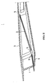
- Fig. 3 is a longitudinal sectional view showing various elements present between one anchorage and the other anchorage of an outer cable.
- Fig. 4 is a sectional view of a sheath formed into a bellows-shaped member having a spiral shallow groove.
- Fig. 5 is a view showing the external appearance of the sheath illustrated in Fig. 4.
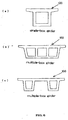
- Fig. 6 show the sectional configurations of typical box girder structures, in which: part (a) is a sectional view of a single-box girder; part (b) is a sectional view of a multiple-box girder; and part (c) is a sectional view of another multiple-box girder having a different configuration.
-
- In the drawings: reference numeral 1 denotes a web; 2 denotes outer cables; 3 denotes an upper floor slab (flange); 4 denotes a lower floor slab (flange); 5 denotes deflectors; 5' denotes through-holes; 6 denotes anchorages; 7 denotes a transparent sheath; 8 denotes a tendon; 9 denotes a grout; 10 denotes a grout injection pipe connecting opening; 11 denotes a drainage hose connecting opening; 71 denotes a spiral crest portion; 72 denotes a spiral shallow groove portion (root portion); 12 denotes diabolos (curved steel pipes); 13 denotes sheath joints; and 100 denotes a box girder.
- The present invention provides a box girder structure including outer cables disposed in a box girder of a box girder bridge to prestress the box girder, wherein each outer cable is disposed in a transparent sheath so that inspection during injection of a grout into the sheath or inspection of the condition in the sheath and refilling of the grout into a vacant space in the sheath can be performed reliably and easily, and also provides a method of building the box girder structure.
- In this specification, the term "box girder" means, as shown in Fig. 1, a beam having a box-shaped cross-section (hollow closed cross-section) 100 formed by upper and
lower flanges flanges box girder 100 include a single-box girder and a multiple-box girder. Parts (a), (b) and (c) of Fig. 6 show examples of the sectional configurations of such box girders. However, the present invention is not necessarily limited to the illustrated box girders but may include any bridge structure suitable for disposing outer cables for prestressing. - In this specification, the term "box girder bridge" means a bridge of the type in which a box girder is supported by abutments or piers. However, there is no particular restriction on the type of bridge. The present invention may include any type of bridge that is known to those skilled in the art or readily available, provided that the bridge can use a transparent sheath for an outer cable for prestressing. The term "prestressing" means previously applying stress to cancel the tensile stress to concrete in a direction opposite to a direction in which tensile stress may be applied to the concrete, that is, previously applying compressive stress (tensioning force of prestressing steel that is introduced into the girder cross-section). The term "outer cable" means a cable made of steel or the like which is provided to prestress concrete. More specifically, the outer cable is provided out of the concrete member in cross-section of a girder (i.e. in the space inside the box girder cross-section).
- In this specification, the term "transparent" used in the term "transparent sheath" means, for example, that the filling condition of a grout being filled into the sheath can be visually observed from the outside of the sheath. It is possible to use a sheath having any property as long as it performs the above-described function. The term "transparent sheath" may mean a sheath having light transmission properties, for example. Light in this case may mean visible light. The term "sheath" means a hollow, typically tubular, or duct member that can pass a prestressing steel in the hollow portion thereof. The sheath performs the function of sheathing the prestressing steel extending through the hollow portion. There is no particular restriction on the shape of the sheath. It is possible to use any type of sheath that is known to those skilled in the art or readily available, provided that the selected sheath can pass a prestressing steel in the hollow portion thereof.
- Embodiments of the present invention will be described below with reference to the accompanying drawings.
- Fig. 1 is a sectional view of a box girder constituting a bridge, and Fig. 2 is a vertically sectioned perspective view showing a central portion of the box girder, which is partly sectioned in the longitudinal direction.
- Fig. 3 is a vertical sectional view showing various constituent elements present between two anchorages of a single outer cable, in which the distance between the two anchorages is reduced. Fig. 4 is a sectional view of a sheath formed into a bellows-shaped member, particularly a bellows-shaped member having a spiral shallow groove, to impart flexibility to the sheath. Fig. 5 is a view showing the external appearance of the sheath illustrated in Fig. 4. Fig. 6 show the sectional configurations of typical box girder structures, in which: part (a) is a sectional view of a single-box girder; part (b) is a sectional view of a multiple-box girder; and part (c) is a sectional view of another multiple-box girder having a different configuration.
- First, as shown in Figs. 1 and 2, a large number of
outer cables 2 are disposed in the space inside the webs 1 of abox girder 100 constituting a bridge, which is formed from a concrete structure. Thus, it is possible to reduce the thickness of the webs 1 and hence possible to achieve a reduction in weight of the box girder structure. - An
upper floor slab 3 is provided at the top of the box girder to form a road surface on which vehicles will drive. Concretestructures constituting deflectors 5 are provided on the side surfaces of the box girder at intervals necessary. The concrete structures are integral with the webs 1. - Each of the
outer cables 2 for prestressing the box girder extends through a through-hole 5' provided in adeflector 5 to change its stretching direction and then passes through a through-hole 5' in anotherdeflector 5 to reach ananchorage 6 at each end of thecable 2 where it is secured. Thecable deflectors 5 are provided to change the cable stretching direction so as to produce prestressing forces in the vertical direction of the structure through contacting pressures at deflectors. Referring to the sectional view of a cable shown in Fig. 3, a cable used in a box girder for an ordinary bridge includes one or a plurality of prestressing steel wires or steel strands each consisting of a large number of thin steel wires, which are bundled to form atendon 8. Thetendon 8 is inserted into asheath 7. Vacant spaces in thesheath 7 are fully filled with a grout 9. Thus, the cable looks like a thick rope. Tensioning force is applied to the cable at theanchorages 6 provided at both ends of the box girder. The tensioning force is constantly maintained even in actual use to maintain the load-carrying capacity of the concrete structure and to prevent failure due to harmful cracking or the like. - The
transparent sheath 7 according to the present invention is a transparent pipe made of a transparent resin material selected from among a vinyl chloride resin material, a polyethylene resin material, a polypropylene resin material, a polycarbonate resin material, a Teflon resin material and so forth, or a composite material consisting of two or more of these materials, or other transparent materials. - A vinyl chloride pipe is suitable from the viewpoint of economy and properties. Usually, a reeled vinyl chloride pipe of continuous length (about 50 meters at maximum) is unreeled at the site of construction when installed. However, cut lengths of vinyl chloride pipe may be connected together to form the whole length of sheath at the site of construction.
- In view of the installing operation at the site of construction, it is preferable to make the sheath transparent and flexible. It is particularly preferable to form the sheath into a bellows-shaped member having a spiral shallow groove as shown in Figs. 4 and 5. By doing so, the sheath is improved in handling properties required in a bending operation and so forth. In the figures,
reference numeral 71 denotes a spiral crest portion, andreference numeral 72 denotes a spiral shallow groove portion (root portion). - In the
sheath 7 shown in Figs. 4 and 5, the crest portion of the bellows-shaped member, which constitutes thesheath 7, is formed by thespiral crest portion 71, and the root portion of the bellows-shaped member is formed by the spiralshallow groove portion 72. Therefore, as grout is filled into thesheath 7 from one end thereof, air at the inner surface of the sheath pipe wall spirally moves toward the other end along the inner side of thespiral crest portion 71. As a result, no air collects at the inner surface of the sheath pipe wall. Accordingly, the effect of thesheath 7 further improves. - For the
tendon 8 constituting the cable, it is also possible to use a fiber-reinforced plastic material, which is reinforced with reinforcing fiber, e.g. carbon fiber, in addition to steel. However, steel is often used from the viewpoint of economy. As steel used for thetendon 8, an appropriate steel material may be selected from those which are widely known to those skilled in the art as prestressing steel or from those developed for use as prestressing steel. - A plurality of
deflectors 5 are provided inside the central portion of the box girder of the bridge. A curved steel pipe known as adiabolo 12 is provided in eachdeflector 5 for each cable. The curved steel pipe allows the cable to be brought into surface contact with thesheath 7 forming the outer surface of the cable, thereby reducing frictional resistance and thus allowing the cable to move smoothly during prestressing. It should be noted that an effective way of further reducing the frictional resistance is to form a polyethylene sheet on the surface of thediabolo 12. Contacting pressure occurring at thedeflector 5 is likely to impose a load locally on sheathing enveloping thetendon 8 in thesheath 7. To prevent this problem, spacers for reducing friction are placed through the curved steel pipe. To reduce cost of material and labor transparent resin sheathing can be cast directly in concrete of the deflector. - Next, the substance of operations based on the present invention will be described.
- After the
outer cables 2 have been tensioned to effect prestressing and anchored at both ends of the box girder, in a typical example, an injection hose is attached to a connecting opening for grouting provided at anendmost portion 10 of thesheath 7 at theanchorage 6. Usually, cement or resin milk is used as a grout, and it is injected by using a grout pump (with a maximum capacity of about 15 atm pressure, in general). An effective way of allowing the sheath to be smoothly exhausted of air during grouting is to provide an exhaust opening in the sheath at a relatively high cable position. The condition of the grout being filled into thesheath 7 can be observed through thetransparent sheath 7 at any time. Thus, it is possible to continue the operation while appropriately controlling or changing grouting conditions so that air bubbles will not remain in thesheath 7. When the injected grout has been fully filled in thesheath 7 and reached the other end of the cable, the completion of filling can be confirmed by ascertaining that a grout component has been discharged from a discharge hose connecting opening 11 provided at theanchorage 6, or finally ascertaining that the grout has been discharged from an exhaust opening separately provided at a high cable position. A vacant space occurring in the cable during use can be readily discovered by usual routine inspection performed in the box girder. If necessary, repair may be executed by locally carrying out additional grouting in the vicinity of a portion where a vacant space has occurred, thereby making it possible to improve durability and to increase the lifetime. - It is even more desirable to inject a colored grout prepared by mixing a grout with a small amount of an inorganic coloring material, e.g. chromium oxide, iron oxide, copper oxide, or manganese oxide, or an organic coloring material. By doing so, the filling condition of the grout in the transparent sheath can be grasped even more clearly. It is preferable to adjust the degree of pigmentation so that the color of the grout is not very deep but sufficiently noticeable to allow a vacant space to be readily found.
- When a vacant space is found in a transparent sheath already filled with a grout, it is preferable to carry out regrouting by sticking a needle portion of an injector-shaped grouting device into the transparent sheath as far as the vacant space and injecting it with the grout.
- The present invention will be described below more specifically by way of an example. It should be understood, however, that the present invention is not necessarily limited to the example but includes various embodiments.
- To confirm the validity of the present invention, we carried out an actual-scale experiment. The outline of the experiment is as follows:
-
- Sheath:
- Transparent vinyl chloride pipe (outer diameter: 114 millimeters; length: 13.5 meters)
- Anchorage:
- Anchorage for the Anderson method (Anderson Technology)
- Steel:
- Bare strands of 15.2 mm outside dia. (19 strands of 13.5 m length)
- Grout:
- Portland cement mixed with Pozzolis GF-1720 (admixture; trade name)
-
- An anchorage for the Anderson method was installed at one end of the sheath, and a water stop jig was installed at the other end of the sheath. Strands (19 strands) were inserted into the sheath. Then, the grout was injected into the sheath, and the process of injection was observed. After a collection of air had been found above deflectors, a discharge hose was opened to remove the air. After the sheath had been injected with the grout, it was possible to check the injected condition over the entire length of the sheath. Further, a colored grout was injected into the sheath. As a result, it became markedly easy to check movement of the grout in the sheath.
- The above-described results proved that the application of the transparent sheath makes it possible to reliably confirm the grouting condition while following the movement of the grout in the sheath and hence possible to fill the grout fully. In particular, it was proved that inspection and confirmation can be made easily and reliably by visual observation.
- It should be noted that, in the cable configuration, a portion of each cable that extends along the lower floor slab of the box girder is likely to be fully filled with the grout because air bubbles getting mixed therein during grouting and vacant spaces produced in the sheath are likely to move upwardly and be replaced by the grout. Therefore, an opaque sheath, which is less costly, can be used for the sheath at this portion.
- According to the present invention described above, it becomes possible to perform inspection and confirmation extremely reliably and easily when prestressing is newly done and also when the occurrence of a vacant space in cables being used is inspected and confirmed in the field of outer cables for box girder bridges where it has heretofore been difficult to grasp the filling condition of a grout in the sheath of each outer cable. In particular, when a colored grout is injected, the confirmation of the filling condition is further facilitated.
- When prestressing steel is used as tendons, fully filling of a grout is indispensable for enhancing anti-corrosion effect. In this regard, because it is possible to readily discover partial fracture or other damage to tendons of various kinds, the reliability of cable maintenance is improved to a considerable extent, and the lifetime of the box girder bridge itself can be increased.
- It will be apparent that the present invention can also be carried out in fonts other than those stated specifically in the foregoing description and example. Various changes and modifications of the present invention may be made in light of the above-described teachings. Accordingly, such changes and modifications also fall within the scope of the appended claims.
- In addition, it will be apparent that the technique of the invention in this application is applicable not only to concrete girders but also to girder structures made of steel as it is.
Claims (11)
- A box girder structure comprising outer cables disposed in a box girder of a box girder bridge to prestress said box girder, said outer cables each having a transparent sheath.
- A box girder structure according to claim 1, wherein said sheath covers the outer cable and makes it possible to perform reliably and readily through visual observation an operation selected from the group consisting of inspection during injection of a grout into said sheath, inspection of condition in said sheath and refilling of the grout into a vacant space in said sheath.
- A box girder structure comprising outer cables disposed in a box girder of a box girder bridge to prestress said box girder, said outer cables each having a transparent sheath injected with a colored grout.
- A box girder structure according to claim 3, wherein said sheath covers the outer cable and makes it possible to perform reliably and readily through visual observation an operation selected from the group consisting of inspection during injection of the grout into said sheath, inspection of condition in said sheath and refilling of the grout into a vacant space in said sheath.
- A box girder structure according to any of claims 1 to 4, wherein said transparent sheath is made of a material selected from the group consisting of a polyethylene resin material, a vinyl chloride resin material, a polypropylene resin material, a polycarbonate resin material and a Teflon resin material, or a composite material consisting of two or more of these materials.
- A box girder structure according to any of claims 1 to 5, wherein transparent sheath is directly cast in concrete of deflector or curved steel pipes are provided in deflectors to dispose said outer cables.
- A box girder structure according to claim 6, wherein said curved steel pipes each have an inner surface coated with polyethylene.
- A method of building a box girder of a box girder bridge, said method comprising the steps of:disposing outer cables each having a transparent sheath to install tendons for prestressing said box girder; andinjecting a grout into said sheath while observing and inspecting a filling condition in said sheath from an outside thereof.
- A method according to claim 8, wherein the filling condition in said sheath covering the outer cable is observed and inspected from the outside of said sheath during injection of the grout or after the grout has hardened.
- A method of building a box girder of a box girder bridge, said method comprising the steps of:disposing outer cables each having a transparent sheath to install tendons for prestressing said box girder in a longitudinal direction of said box girder bridge; andinjecting a colored grout into said sheath while observing and inspecting a filling condition in said sheath from an outside thereof.
- A method according to claim 10, wherein the filling condition in said sheath covering the outer cable is observed and inspected from the outside of said sheath during injection of the grout or after the grout has hardened, and if found, an unfilled portion is refilled with the grout.
Applications Claiming Priority (4)
| Application Number | Priority Date | Filing Date | Title |
|---|---|---|---|
| JP13587899 | 1999-05-17 | ||
| JP13587899 | 1999-05-17 | ||
| JP2000114353 | 2000-04-14 | ||
| JP2000114353A JP2001032211A (en) | 1999-05-17 | 2000-04-14 | Box girder structure of bridge with external cables and method of building the same |
Publications (2)
| Publication Number | Publication Date |
|---|---|
| EP1054106A2 true EP1054106A2 (en) | 2000-11-22 |
| EP1054106A3 EP1054106A3 (en) | 2002-07-03 |
Family
ID=26469619
Family Applications (1)
| Application Number | Title | Priority Date | Filing Date |
|---|---|---|---|
| EP00110193A Withdrawn EP1054106A3 (en) | 1999-05-17 | 2000-05-16 | Box girder structure for bridge provided with outer cable and method of building the box girder |
Country Status (4)
| Country | Link |
|---|---|
| US (1) | US7104017B1 (en) |
| EP (1) | EP1054106A3 (en) |
| JP (1) | JP2001032211A (en) |
| KR (1) | KR20000077301A (en) |
Cited By (13)
| Publication number | Priority date | Publication date | Assignee | Title |
|---|---|---|---|---|
| EP1239084A3 (en) * | 2001-03-06 | 2003-11-19 | VORSPANN-TECHNIK Ges.m.b.H. & Co. KG | Building structure with concrete walls and formwork for a building structure |
| EP1191164A4 (en) * | 2000-03-02 | 2004-03-10 | Anderson Technology Corp | Pc steel stranded wire connection structure and construction method thereof |
| KR100432494B1 (en) * | 2001-09-07 | 2004-05-22 | (주)스틸엔콘크리트 | wide precast concrete girder block and construction method of a bridge using the same girder block |
| EP1441070A4 (en) * | 2001-10-29 | 2005-03-16 | Anderson Technology Corp | TRANSPARENT PROTECTION TUBE FOR EXTERNAL CABLE |
| WO2006007660A1 (en) * | 2004-07-21 | 2006-01-26 | Murray Ellen | Building methods |
| FR2880638A1 (en) * | 2005-01-12 | 2006-07-14 | Jean Marie Beauthier | Bridge for sparing passage under e.g. railway lane, has side sections extending beyond its junction with inclined wall and including two ears that are articulated between vertical and stable positions in extension of side sections |
| US8443572B2 (en) | 2004-07-21 | 2013-05-21 | S2 Holdings Pty Limited | Building methods |
| CN104675023A (en) * | 2013-11-29 | 2015-06-03 | 甘肃路桥建设集团有限公司 | Accurate positioning device for corrugated pipe |
| CN105648890A (en) * | 2016-03-18 | 2016-06-08 | 大连理工大学 | U-shaped prestressed structure for webs and bottom board of concrete box beam |
| CN108517783A (en) * | 2018-04-28 | 2018-09-11 | 中交航局第工程有限公司 | A kind of 200m box beams duct relay grouting process |
| CN110374004A (en) * | 2019-07-10 | 2019-10-25 | 江苏镇江路桥工程有限公司 | A kind of presstressed reinforcing steel mud-jacking technology |
| CN110453603A (en) * | 2019-07-16 | 2019-11-15 | 中冶交通建设集团有限公司 | Overpass crossbeam construction method |
| CN114855617A (en) * | 2022-04-18 | 2022-08-05 | 中交二公局东萌工程有限公司 | External prestress construction method for newly-built variable-cross-section continuous beam bridge |
Families Citing this family (12)
| Publication number | Priority date | Publication date | Assignee | Title |
|---|---|---|---|---|
| KR100466017B1 (en) * | 2001-09-21 | 2005-01-13 | 명보산공 주식회사 | The Method of Reinforce Steel Box Girder type Bridge and The Structure thereof |
| US6955013B2 (en) * | 2002-09-26 | 2005-10-18 | Thompson Harry A | End cap locking mechanism for connecting pre-cast concrete structures |
| WO2005116366A1 (en) * | 2004-05-31 | 2005-12-08 | Anderson Technology Corporation | Grout injection construction method including evacuation process in cable sheath of outer cable type pc structure |
| EP1802813A4 (en) * | 2004-09-25 | 2013-03-20 | Univ Ajou Ind Coop Foundation | PRECONTRAINT CAVERNEUX CONCRETE BEAM (HPC) AND METHOD FOR CONSTRUCTING A BRIDGE WITH PRECONTRATED SPINNED CAWN CONCRETE BEAM (S-HPC) |
| KR100935636B1 (en) * | 2008-05-19 | 2010-01-07 | (주)유진기업 | Flexural relaxation method and device for prestressed concrete girder reinforcement |
| JP2010174423A (en) * | 2009-01-30 | 2010-08-12 | Sumitomo Denko Steel Wire Kk | Inspectable polyethylene-coated epoxy strand |
| KR100969357B1 (en) * | 2010-02-18 | 2010-07-09 | 주식회사 대산시빌테크날러지 | Psc girder with open upper part and support internal wall and single or continuous bridge construction method therewith |
| JP6315384B2 (en) * | 2014-12-22 | 2018-04-25 | 株式会社富士ピー・エス | PC grout filling status monitoring method and PC grout construction management method |
| EP3543418B1 (en) * | 2018-03-23 | 2021-05-12 | Soletanche Freyssinet | Method for connecting precast segments tendon ducts and resulting structure |
| CN111677190A (en) * | 2020-01-15 | 2020-09-18 | 柳州市桥厦工程管材有限公司 | a flat cord |
| CN112049027A (en) * | 2020-09-04 | 2020-12-08 | 上海市机械施工集团有限公司 | Remediation method for prestressed duct |
| CN119777274B (en) * | 2025-03-10 | 2025-07-04 | 陕西高速机械化工程有限公司 | A cast-in-place box girder steel strand threading device and threading method |
Citations (2)
| Publication number | Priority date | Publication date | Assignee | Title |
|---|---|---|---|---|
| JPH04182568A (en) | 1990-11-16 | 1992-06-30 | Nippon Kensetsu Kikaika Kyokai | Interposal state detecting method of filling grout in concrete structure and device thereof |
| JPH1054140A (en) | 1996-08-09 | 1998-02-24 | Hihakai Kensa Kk | Grout filling condition inspection method |
Family Cites Families (16)
| Publication number | Priority date | Publication date | Assignee | Title |
|---|---|---|---|---|
| AT320243B (en) * | 1970-11-03 | 1975-01-27 | Schmitter Adolf | Box girder and process for its manufacture |
| US3979896A (en) * | 1975-02-24 | 1976-09-14 | The United States Of America As Represented By The Secretary Of The Navy | Impregnated and encapsulated wire rope and cable |
| DE3109414A1 (en) * | 1981-03-12 | 1982-10-21 | Heilit + Woerner Bau-AG, 8000 München | Device for the installation of movable prestressing-member couplings |
| DE3523747A1 (en) * | 1985-07-03 | 1987-01-15 | Paul Larsen Roenne A S | CONTAINER WITH A RING-SHAPED TERMINAL BUILT ON A FLOOR PANEL |
| DE3734953C2 (en) | 1987-03-13 | 1994-02-24 | Dyckerhoff & Widmann Ag | Spacer for a tension member |
| CH676617A5 (en) | 1987-03-13 | 1991-02-15 | Dyckerhoff & Widmann Ag | |
| FI79588C (en) * | 1987-05-05 | 1990-01-10 | Kautar Oy | Pre-tensioned building element with composite construction and method of manufacture thereof |
| ES2042271T5 (en) | 1989-04-12 | 1997-11-01 | Vorspann Technik Gmbh | TENSIONING GROUP OF VARIOUS TENSIONING ELEMENTS SUCH AS LACES, RODS OR WIRES. |
| US5437072A (en) * | 1992-01-23 | 1995-08-01 | J. Muller International | Rapid transit viaduct with post-tensioning cable system |
| FR2717465B1 (en) | 1994-03-21 | 1996-04-26 | Rhone Poulenc Chimie | Injection grout to coat a reinforcement, in particular a prestressing reinforcement. |
| US5540030A (en) * | 1994-07-01 | 1996-07-30 | Morrow; Jack A. | Process for the grouting of unbonded post-tensioned cables |
| JPH08100530A (en) * | 1994-09-30 | 1996-04-16 | P C Kyoryo Kk | Post-tensioning grout injection method for prestressed concrete and injection confirmation method and injection method |
| IT1275096B (en) * | 1994-12-19 | 1997-07-30 | Pellegrino Gallo | "EARTHQUAKE-PROOF SYSTEM FOR STRUCTURES SUCH BUILDINGS, VIADUCTS, SIMILAR TANKS" |
| DE19634682C2 (en) * | 1996-08-28 | 1999-07-08 | Dyckerhoff & Widmann Ag | Seal for delimiting areas to be filled with a sealing compound on a bundle tension member for prestressed concrete |
| FR2775492B1 (en) * | 1998-02-27 | 2000-05-05 | Freyssinet Int Stup | PREFABRICATED CONSTRUCTION ELEMENTS, PRE-STRESSED STRUCTURE MADE OF SUCH ELEMENTS AND METHOD FOR MANUFACTURING SUCH ELEMENTS |
| JP3519311B2 (en) * | 1999-05-07 | 2004-04-12 | 日本道路公団 | Synthetic resin pipe for cable protection |
-
2000
- 2000-04-14 JP JP2000114353A patent/JP2001032211A/en active Pending
- 2000-05-15 US US09/571,321 patent/US7104017B1/en not_active Expired - Fee Related
- 2000-05-16 EP EP00110193A patent/EP1054106A3/en not_active Withdrawn
- 2000-05-17 KR KR1020000026374A patent/KR20000077301A/en not_active Withdrawn
Patent Citations (2)
| Publication number | Priority date | Publication date | Assignee | Title |
|---|---|---|---|---|
| JPH04182568A (en) | 1990-11-16 | 1992-06-30 | Nippon Kensetsu Kikaika Kyokai | Interposal state detecting method of filling grout in concrete structure and device thereof |
| JPH1054140A (en) | 1996-08-09 | 1998-02-24 | Hihakai Kensa Kk | Grout filling condition inspection method |
Cited By (19)
| Publication number | Priority date | Publication date | Assignee | Title |
|---|---|---|---|---|
| EP1191164A4 (en) * | 2000-03-02 | 2004-03-10 | Anderson Technology Corp | Pc steel stranded wire connection structure and construction method thereof |
| EP1239084A3 (en) * | 2001-03-06 | 2003-11-19 | VORSPANN-TECHNIK Ges.m.b.H. & Co. KG | Building structure with concrete walls and formwork for a building structure |
| KR100432494B1 (en) * | 2001-09-07 | 2004-05-22 | (주)스틸엔콘크리트 | wide precast concrete girder block and construction method of a bridge using the same girder block |
| EP1441070A4 (en) * | 2001-10-29 | 2005-03-16 | Anderson Technology Corp | TRANSPARENT PROTECTION TUBE FOR EXTERNAL CABLE |
| GB2431175B (en) * | 2004-07-21 | 2009-12-02 | Murray Ellen | Building Methods |
| GB2431175A (en) * | 2004-07-21 | 2007-04-18 | Murray Ellen | Building Methods |
| WO2006007660A1 (en) * | 2004-07-21 | 2006-01-26 | Murray Ellen | Building methods |
| US8443572B2 (en) | 2004-07-21 | 2013-05-21 | S2 Holdings Pty Limited | Building methods |
| US8607528B2 (en) | 2004-07-21 | 2013-12-17 | Murray Ellen | Building methods |
| FR2880638A1 (en) * | 2005-01-12 | 2006-07-14 | Jean Marie Beauthier | Bridge for sparing passage under e.g. railway lane, has side sections extending beyond its junction with inclined wall and including two ears that are articulated between vertical and stable positions in extension of side sections |
| EP1681396A3 (en) * | 2005-01-12 | 2006-10-25 | Freyssinet | Bridge the upper slab of which comprises ears |
| CN104675023A (en) * | 2013-11-29 | 2015-06-03 | 甘肃路桥建设集团有限公司 | Accurate positioning device for corrugated pipe |
| CN104675023B (en) * | 2013-11-29 | 2017-08-04 | 甘肃路桥建设集团有限公司 | A kind of bellows accurate positioning device |
| CN105648890A (en) * | 2016-03-18 | 2016-06-08 | 大连理工大学 | U-shaped prestressed structure for webs and bottom board of concrete box beam |
| CN108517783A (en) * | 2018-04-28 | 2018-09-11 | 中交航局第工程有限公司 | A kind of 200m box beams duct relay grouting process |
| CN108517783B (en) * | 2018-04-28 | 2020-08-04 | 中交一航局第一工程有限公司 | Relay grouting process for 200m box girder channel |
| CN110374004A (en) * | 2019-07-10 | 2019-10-25 | 江苏镇江路桥工程有限公司 | A kind of presstressed reinforcing steel mud-jacking technology |
| CN110453603A (en) * | 2019-07-16 | 2019-11-15 | 中冶交通建设集团有限公司 | Overpass crossbeam construction method |
| CN114855617A (en) * | 2022-04-18 | 2022-08-05 | 中交二公局东萌工程有限公司 | External prestress construction method for newly-built variable-cross-section continuous beam bridge |
Also Published As
| Publication number | Publication date |
|---|---|
| JP2001032211A (en) | 2001-02-06 |
| KR20000077301A (en) | 2000-12-26 |
| US7104017B1 (en) | 2006-09-12 |
| EP1054106A3 (en) | 2002-07-03 |
Similar Documents
| Publication | Publication Date | Title |
|---|---|---|
| US7104017B1 (en) | Box girder structure for bridge provided with outer cable and method of building the box girder | |
| EP1219757B1 (en) | Tendon-receiving duct with longitudinal channels | |
| US10077554B2 (en) | Corrosion protection of cables in a concrete structure | |
| CN101215822A (en) | Method and device for anchoring changeable prestressing force of suspension bridge | |
| US20160305140A1 (en) | Method and apparatus for repairing post-tensioned concrete | |
| Soudki et al. | Transfer length of carbon fiber rods in precast pretensioned concrete beams | |
| JP2012112690A (en) | Method for measuring strain of concrete structure | |
| CN115262626B (en) | Construction method of underground space prestress steel reinforced concrete top cover under ultra-large span heavy load | |
| US20050108981A1 (en) | Work method for filling grout into inner cable of post tension system pc structure | |
| HK1034755A (en) | Box girder structure for bridge provided with outer cable and method of building the box girder | |
| RU2131010C1 (en) | Prestressed ferroconcrete constructions | |
| EP3951066B1 (en) | A method of testing a structure, an assembly for testing a structure, and use of an assembly for testing a structure | |
| CN116291637A (en) | Anchor cable reinforcement method | |
| KR100402367B1 (en) | Steel wire for retension of bridge and its retension method | |
| CN108797343B (en) | A semi-grouting sleeve connected prefabricated FRP reinforced concrete central anti-collision guardrail | |
| CN114855617A (en) | External prestress construction method for newly-built variable-cross-section continuous beam bridge | |
| Khalafalla | Development of sustainable concrete bridge deck slab systems using corrosion-resistant GRFP bars | |
| KR100549044B1 (en) | Tensile part reinforcement device and its installation method for load capacity reinforcement on the section under tension of concrete structure | |
| JP7191719B2 (en) | PCaPC floor slab with double-tube structure sheath | |
| JP7760102B1 (en) | Existing pipe rehabilitation method | |
| JP7760103B1 (en) | Existing pipe rehabilitation method | |
| Kamaitis | Field investigation of joints in precast post-tensioned segmental concrete bridges | |
| KR200184685Y1 (en) | Apparatus preventing damage sheath tube of steel wire to restress prestress structure | |
| JP4085726B2 (en) | Reinforcement method for existing structures | |
| JP2739562B2 (en) | Anchor fixing body, method of manufacturing the same, and method of assembling anchor |
Legal Events
| Date | Code | Title | Description |
|---|---|---|---|
| PUAI | Public reference made under article 153(3) epc to a published international application that has entered the european phase |
Free format text: ORIGINAL CODE: 0009012 |
|
| AK | Designated contracting states |
Kind code of ref document: A2 Designated state(s): AT BE CH CY DE DK ES FI FR GB GR IE IT LI LU MC NL PT SE |
|
| AX | Request for extension of the european patent |
Free format text: AL;LT;LV;MK;RO;SI |
|
| PUAL | Search report despatched |
Free format text: ORIGINAL CODE: 0009013 |
|
| AK | Designated contracting states |
Kind code of ref document: A3 Designated state(s): AT BE CH CY DE DK ES FI FR GB GR IE IT LI LU MC NL PT SE |
|
| AX | Request for extension of the european patent |
Free format text: AL;LT;LV;MK;RO;SI |
|
| 17P | Request for examination filed |
Effective date: 20021220 |
|
| AKX | Designation fees paid |
Designated state(s): DE FR GB |
|
| STAA | Information on the status of an ep patent application or granted ep patent |
Free format text: STATUS: THE APPLICATION HAS BEEN WITHDRAWN |
|
| 18W | Application withdrawn |
Effective date: 20050413 |
|
| REG | Reference to a national code |
Ref country code: HK Ref legal event code: WD Ref document number: 1034755 Country of ref document: HK |