EP1053736B1 - Heater door mechanism for infant warming apparatus - Google Patents
Heater door mechanism for infant warming apparatus Download PDFInfo
- Publication number
- EP1053736B1 EP1053736B1 EP00303014A EP00303014A EP1053736B1 EP 1053736 B1 EP1053736 B1 EP 1053736B1 EP 00303014 A EP00303014 A EP 00303014A EP 00303014 A EP00303014 A EP 00303014A EP 1053736 B1 EP1053736 B1 EP 1053736B1
- Authority
- EP
- European Patent Office
- Prior art keywords
- heater
- infant
- doors
- canopy
- door
- Prior art date
- Legal status (The legal status is an assumption and is not a legal conclusion. Google has not performed a legal analysis and makes no representation as to the accuracy of the status listed.)
- Expired - Lifetime
Links
Images


Classifications
-
- A—HUMAN NECESSITIES
- A61—MEDICAL OR VETERINARY SCIENCE; HYGIENE
- A61G—TRANSPORT, PERSONAL CONVEYANCES, OR ACCOMMODATION SPECIALLY ADAPTED FOR PATIENTS OR DISABLED PERSONS; OPERATING TABLES OR CHAIRS; CHAIRS FOR DENTISTRY; FUNERAL DEVICES
- A61G11/00—Baby-incubators; Couveuses
-
- H—ELECTRICITY
- H05—ELECTRIC TECHNIQUES NOT OTHERWISE PROVIDED FOR
- H05B—ELECTRIC HEATING; ELECTRIC LIGHT SOURCES NOT OTHERWISE PROVIDED FOR; CIRCUIT ARRANGEMENTS FOR ELECTRIC LIGHT SOURCES, IN GENERAL
- H05B3/00—Ohmic-resistance heating
-
- A—HUMAN NECESSITIES
- A61—MEDICAL OR VETERINARY SCIENCE; HYGIENE
- A61G—TRANSPORT, PERSONAL CONVEYANCES, OR ACCOMMODATION SPECIALLY ADAPTED FOR PATIENTS OR DISABLED PERSONS; OPERATING TABLES OR CHAIRS; CHAIRS FOR DENTISTRY; FUNERAL DEVICES
- A61G11/00—Baby-incubators; Couveuses
- A61G11/001—Baby-incubators; Couveuses with height-adjustable elements
- A61G11/002—Baby-incubators; Couveuses with height-adjustable elements height-adjustable patient support
-
- A—HUMAN NECESSITIES
- A61—MEDICAL OR VETERINARY SCIENCE; HYGIENE
- A61G—TRANSPORT, PERSONAL CONVEYANCES, OR ACCOMMODATION SPECIALLY ADAPTED FOR PATIENTS OR DISABLED PERSONS; OPERATING TABLES OR CHAIRS; CHAIRS FOR DENTISTRY; FUNERAL DEVICES
- A61G11/00—Baby-incubators; Couveuses
- A61G11/001—Baby-incubators; Couveuses with height-adjustable elements
- A61G11/003—Baby-incubators; Couveuses with height-adjustable elements height-adjustable heater
-
- A—HUMAN NECESSITIES
- A61—MEDICAL OR VETERINARY SCIENCE; HYGIENE
- A61G—TRANSPORT, PERSONAL CONVEYANCES, OR ACCOMMODATION SPECIALLY ADAPTED FOR PATIENTS OR DISABLED PERSONS; OPERATING TABLES OR CHAIRS; CHAIRS FOR DENTISTRY; FUNERAL DEVICES
- A61G11/00—Baby-incubators; Couveuses
- A61G11/005—Baby-incubators; Couveuses with movable walls, e.g. for accessing the inside, removable walls
- A61G11/006—Baby-incubators; Couveuses with movable walls, e.g. for accessing the inside, removable walls by pivoting
-
- A—HUMAN NECESSITIES
- A61—MEDICAL OR VETERINARY SCIENCE; HYGIENE
- A61G—TRANSPORT, PERSONAL CONVEYANCES, OR ACCOMMODATION SPECIALLY ADAPTED FOR PATIENTS OR DISABLED PERSONS; OPERATING TABLES OR CHAIRS; CHAIRS FOR DENTISTRY; FUNERAL DEVICES
- A61G11/00—Baby-incubators; Couveuses
- A61G11/009—Baby-incubators; Couveuses with hand insertion windows, e.g. in the walls
Definitions
- the present invention relates to an infant warming apparatus and, more particularly, to an apparatus for providing the combined functions of an infant incubator and an infant warmer and which includes a radiant heater contained within a housing having a doors that are operable to automatically open and close in accordance with a mechanism.
- infant warmers that are basically planar surfaces on which the infant is positioned and which planar surfaces generally include side guards to keep the infant safely within the confines of the apparatus.
- Infant warmers normally have an overhead radiant heater that is located above the infant and which thus radiates energy in the infrared spectrum to impinge upon the infant to maintain the infant at a warm, predetermined temperature. Since the infant is otherwise totally exposed to the surroundings, there is almost unlimited access to the infant by the attending personnel to perform various procedures on that infant. At typical infant warmer is shown and described in U.S. Patent 5,474,517 of Falk et al as prior art to that patent.
- infant incubators which are more confined enclosures that contain the infant within an enclosed controlled atmosphere in an infant compartment that provides heat to the infant and also may provide control of humidity in the enclosed environment.
- Such incubators maintain the infant for long periods of time and include handholes to access the infant and/or there is normally a larger access door that can be opened to access the infant or to insert or remove the infant to and from the incubator.
- Such devices provide a good atmosphere to the infant and control that local environment within which the infant is located, however, it is sometime difficult to perform a wide variety of procedures on the infant due to the somewhat limited access to that infant.
- a typical infant incubator is shown and described in U.S. Patent 4,936,824 of Koch et al.
- the heater when the heater is lowered, there are still surfaces of the heater and its housing that are hot spots and which continue to radiate heat that is focused in the direction of the infant only at that point, the heater is located at a close proximity to the infant.
- those hot spots can cause localized heated areas of the infant and the effect potentially harmful to the infant. It is therefore, important that some means be provided to prevent those surfaces from radiating to the infant or from being inadvertent touched by the infant or any of the attending personnel.
- W097/11664 and WO 99/12512 disclose an infant care apparatus that combines the functions of an infant care warmer and an incubator, the hood of the incubator can be raised to form a radiant heater.
- the hood is formed in two parts and, when raised, the two parts are pivoted.
- the present invention relates to an infant care apparatus as defined in the accompanying claims; more especially, it combines the functions of an infant care warmer and an incubator but in addition, has a door or doors that can close when the canopy including the radiant heater is lowered toward the infant and open when the canopy and heater are again raised to the upper position.
- the heater itself as well as the surrounding housing adjacent surfaces that are heated by the conduction from the radiant heater are concealed from the user and the infant when in its lower position and the doors thus block further radiant heat and convective heat from reaching the infant.
- that closed status is automatically achieved by the mechanism as the heater canopy progresses from its upper position to its lower position and the door or doors are safely closed without some reminder or action on the part of a user.
- the door or doors automatically open so that the heater can be energized to direct radiant infrared energy to impinge upon the infant.
- the operation of the mechanism is automatic and needs no action on the part of a user other than to indicate to the infant warming apparatus what warmer position is desired at the time.
- each door that open and close to contain the heater as with only one door, it is possible in a failure mode, that if the door does not close upon reaching its lower position, the door has sufficient width that it may actually touch the infant. With two doors, each door is reduced in width such that the danger of the door touching the infant in the lower position is eliminated.
- a mechanism is provided that is a mechanical system that opens and closes the doors as the heater moves, respectively, to the upper position and to the lower position.
- the actual opening and closing take place at or near the upper position. It is preferable that the mechanism operate such that the doors open and close at a point within no more than about 12 inches (30 cm) from the upper position, and more preferably 6-8 inches (15-20 cm). In that manner, there is some assurance that the door does not open as the heater canopy is moving upwards until the heater canopy has reached almost to its upper position so that the doors do not open to present a hazard at a low position where the heater could still be within the reach of the infant or other persons. More importantly, the heater doors close immediately upon being lowered, again within 6-8 inches (15-20 cm) and thus insures that the doors are fully closed before the heater can reach any lower height where it could be reached by the infant and the attending personnel.
- vent opening in the heater housing that allows the natural convective circulation of air when the radiant heater is activated.
- the convective cooling prevents the heater from overheating within the heater housing. While it is an important function to allow such cooling when the radiant heater is activated, the presence of a vent opening in its open position can also be a hazard without some protection when the heater canopy is in its lower position.
- a vent flap is provided that opens and closes the vent opening so that the vent flap, at the lower position of the heater canopy, effectively closes the vent opening so that the internal components of the heater housing cannot be reached by persons in proximity to the infant warming apparatus.
- the opening and dosing of the vent flap is automatic and operates without any action on the part of the user.
- the vent flap automatically closes in a positive manner and, conversely, as the heater canopy is raised, the vent flap opens so that the natural convective flow of cooling air is available wherever the radiant heater is activated.
- both the vent flap is biased toward its open, or safest position, while the doors protecting the heater are biased toward their closed position, again , the safest position of the doors in the even of a failure of any one or more of the actuating mechanisms.
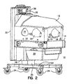
- FIG. 1 there is shown a perspective view of an infant warming apparatus 10 constructed in accordance with the present invention with the heater canopy 12 in its upper position.
- Figure 2 there is a perspective view of the infant warming apparatus 10 as shown in Figure 1 but with the heater canopy 12 in its lower position.
- the infant warming apparatus 10 acts as an infant warmer with considerable access to the infant for performing interventions on the infant and in the Figure 2 configuration, the infant warming apparatus 10 acts as an incubator with the infant confined within a protective environment and having a controlled atmosphere to provide warmth as well as controlled humidity.
- the infant warming apparatus 10 includes an infant pedestal 14 that underlies and supports an infant.
- a plurality of walls 16 are provided to contain the infant safely within the infant warming apparatus 10 and are located at all of the four sides of the infant pedestal 14.
- the walls 16 are preferable constructed of transparent plastic material and, as will be explained, cooperate with other components in order to provide an incubator function to the infant warming apparatus 10 when in the Figure 2 configuration.
- the infant pedestal 14 is mounted to a vertical movable base member 18 which, in the preferred embodiment, is movably affixed to a stationary vertical base member 20, which, in turn, is mounted to a base 22 having wheels 24 for ready movement of the infant warming apparatus 10.
- the vertical movable base member 18 is preferably mounted so that the user can adjust the height of the infant pedestal 14 by raising and lowering the movable vertical member 18 as desired, thus the infant pedestal 14 can be adjusted to the preferred height by the user.
- the walls 16 have handholes 26 to afford access to the infant when in the incubator configuration of Figure 2, and which generally have doors 28 that can be opened to obtain access to the infant and, of course, closed when the particular intervention has been completed to preserve the desired environment within the incubator configuration.
- Another convenient feature includes a drawer 30 to retain supplies or other devices needed to carry out some operation on the infant and which is normally located beneath the infant pedestal 14.
- Other features include the maneuverability of the walls 16 that are pivotally mounted at their bases to the infant pedestal 14 such that the doors can be swung outwardly and downwardly and, as a further alternative, can be easily fully removed from the infant pedestal 14. As such, therefore, when the heater canopy 12 of the infant warming apparatus 10 is in its upper position as shown in Fig 1, the walls 16 can be dropped downwardly or removed altogether so that the attending personnel can have unlimited access to an infant resting on the infant pedestal 14 to perform interventions on that infant.
- FIG. 10 Further structural components of the infant warming apparatus 10 include stationary frame members 32 that are affixed to the vertical movable base member 20 and, as shown, there are two vertical stationary frame members 32 in the preferred embodiment although there may be only one or there may be further numbers of such members.
- Two movable frame members 34 are movably fitted into the stationary frame members 32 and which can be moved upwardly and downwardly by the user as will be explained.
- a control module 36 is conveniently positioned intermediate the stationary frame members 32 and may include displays of various monitored parameters as well as include the various controls for operation of the functions of the infant warming apparatus 10.
- the heater canopy 12 houses a radiant heater (not shown in Figures 1 and 2) as will be later explained.
- the heater canopy 12 can be moved between its lower position as shown in Figure 2 and its upper position as shown in Figure 1 depending upon the mode of operation desired by the user.
- the infant care apparatus 10 functions as an infant warmer where there is full access to the infant and where an overhead radiant warmer supplies heat to maintain the infant with sufficient warmth.
- the infant warming apparatus 10 functions as a normal incubator, since the outer periphery of the infant canopy 12 fits fully over the upper edges of the walls 16 to form therein an infant compartment that is provided with warm air and controlled humidity in the normal functioning of an incubator.
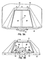
- FIG. 3A a bottom isometric view of the heater canopy 12 and an end isometric view of the heater canopy 12 where the heater canopy 12 is in its tower position, that is, in the position as shown in Figure 2.
- Fig. 3A there is a pair of doors 38 that are shown in the closed position and where the doors 38 overlap to a certain degree at overlap 40.
- two doors 38 are used in carrying out the present invention.
- There is a disadvantage with only one door in that the door needs to have a considerable width and so, if a fault occurs and the door does not fully close during its descent to its lower position, it can extend into the infant compartment when in the lowered position.
- the radiant heater not shown in Fig. 3A, is safely contained within the heater canopy 12 and is protected by the doors 38 from being touched by the infant within the infant warming apparatus 10; the doors also any further radiant or convective heat being directed toward the infant from heated surfaces within the heater canopy 12.
- the infant canopy 12 can, at this point, be safely in its lower position since any further heat is blocked by the doors 38 from reaching the infant and the radiant heater is protected from inadvertenttouching by the infant or by any of the attending personnel.
- the doors 38 are pivotally mounted to the heater canopy 12 at pivot points 42 and 44 at one side of the doors and at pivot points 46 and 48 at the other side of the doors 38 so that the doors 38 can move between their open and closed positions.
- Each door has a door pivot arm 50 that is connected to and causes the movement of the doors 38, that is, as the door pivot arm 50 is rotated, the corresponding door 38 also pivots so that the door pivot arms 50 basically are rotated to move the doors 38 between their open and closed positions.
- Further connected to the door pivot arms 50 are a pair of door links 52 and which, in turn cause the door pivot arms 50 to rotate.
- both of the door links 52 are pivotally connected to a cable spool 54 and which, itself, is rotatably affixed to the heater canopy 12 at the centerpoint 56 of the cable spool 54 such that the points of affixation of both of the door links 52 are at predetermined radii from that centerpoint 56.
- the cable spool 54 rotates about its centerpoint 56, the door links 52 move and thereby cause the door pivot arms 50 to correspondingly move to pivot the doors 38 between open and closed positions.
- the cable spool 54 is rotatable to open and close the doors 38 by means of the linkages, i.e. door links 52 and door pivot arms 50.
- a cable 58 is partially wrapped about the outer periphery of the cable spool 54 and its use will be later explained, it being enough to note that the pulling of the cable 58 serves to rotate the cable spool 54 and thus operate the doors 38.
- the cable spool 54 is also spring biased toward its clockwise or closed door position by means of a spiral spring, not shown in Figs. 3 and 3A.
- FIGs 4A and 4B there is shown, respectively, a bottom isometric view of the heater canopy 12 and an end isometric view of the heater canopy 12 showing the doors 38 in their open position, that is, when the heater canopy 12 is in its upper position as shown In Figure 1.
- the cable spool 54 has been rotated from its position in Figures 3A and 3B, resulting in the doors 38 being rotated to their open position and which increases the tension on the spring 55 to cause the spring 55 to more tightly coil and create a bias in the clockwise direction of the cable spool 54 biasing the doors 38 toward their closed positions.
- a radiant heater 60 is present and which provides the radiant energy in the infrared spectrum to impinge upon an infant when positioned in the infant warming apparatus 10.
- the radiant heater 60 of the preferred embodiment includes an infrared emitter 62 that provides the infrared radiation and which is reflected towards an infant by means of reflector 64.
- the reflector 64 is preferable of a particular geometric configuration such as an ellipsoid, a paraboloid or an hyperboloid.
- a deflector 66 is used to deflect some of the infrared energy otherwise directed toward an infant back toward and then re-reflected from the reflector 64.
- a heat shield 68 is mounted on the downward side of the deflector 66 to prevent the high temperature of the deflector 66 from being accessible by the user.
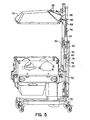
- FIG. 5 there is shown a side view, partly in cross section, to illustrate the operation of the mechanism to operate the doors 38 as the heater canopy 12 is moved between its extreme positions, that is, from the upper position to the lower position and vice versa.
- a heater door activation rod 70 that is fixed at its base to a bracket 72.
- Activation rod 70 is contained within one of the stationary frame member 32 and thus is internal of the unit itself.
- a heater door activation tube 74 is coaxially, slidingly positioned around the activation rod 70 such that the activation tube 74 can slide along the activation rod 70 about the external surface thereof.
- a spring 76 fixed at its upper end to the top of the activation rod 70 and its lower end is suspended downwardly and is free standing.
- the bottom of the activation tube 74 is fitted with a cup 78 that is adapted to contact the lower end of the spring 76 in a manner that will be explained.
- the cable 58 is affixed to the upper end of the activation tube and the cable thereafter passes through a cable slide 80 in the movable frame member 34 to be affixed to the periphery of the cable spool 54 (Figs. 3B and 4B).
- the operation of the door actuating mechanism can now be described.
- the movable frame member 34 moves upwardly guided by a plurality of rollers 82. Since the actuation rod 70 is fixed at its lower end to the bracket 72, the activation rod 70 is stationary but the activation tube 74, being fixed to the movable frame member 34 moves upwardly.
- the cup 78 at the bottom of the actuation tube 74 engages the lower end of the spring 76 and thus the further upward movement of the activation tube 74 is constrained.
- the cable 58 does not start to activate the doors 38 to move the doors 38 to their open position until the activation tube 74 has moved upwardly a predetermined distance.
- the advantage of such mechanism is that the doors 38 do not start to open immediately upon the initiation of the upward movement of the heater canopy 12 and thus the movement of the doors 38 is delayed until the heater canopy 12 is safely out of the reach of an infant positioned on the infant pedestal 14 or the attending personnel.
- the mechanism is dimensioned such that the doors 38 open and close within the upper 6-8 inches (15-20 cm) of travel with respect to the upper position of the heater canopy 12.
- FIG. 6A and 6B there are shown side cross-sectional views of the heater canopy 12 constructed in accordance with the present invention and illustrating a further feature of the subject invention.
- vent flap 84 that is pivotally movable and which is in its open position in Fig. 6A indicative of the position of Fig. 1 where the heater canopy is in its upper position and in the closed position in Fig. 6B indicative of the heater canopy 12 in the lower position as shown in Fig. 2.
- the vent flap 84 is biased toward its open position by means of a vent spring 86, shown schematically, acting against the vent flap 84.
- a vent spring 86 shown schematically, acting against the vent flap 84.
- vent opening 88 formed in the heater housing 90 and which, when open, provides a venting of the heated surfaces within the heater housing to prevent overheating of the radiant heater 60 and its associated structure.
- the vent flap 84 is in it open position so that it is in that position when the radiant heater 60 is activated so that the natural convection will provide a cooling effect to the components within the heater housing.
- the vent flap 84 covers the vent opening 88 and therefore there is no such natural convective cooling.
- the heater canopy 12 is in its lower position and the radiant heater 60 is inactivated. In that position, there is a possibility of an attending person inadvertently touching any one or more of the components internal of the heater housing 90 and which component may still be heated.
- vent flap 84 the natural convective cooling can take place with the radiant heater 60 contained within the heater canopy 12 when in its upper position out of reach of the attending personnel but the vent flap 84 is closed when the heater canopy 12 is in its lower position to provide protection against the inadvertent touching by such personnel.
- vent flap 84 is automatically in the proper position when the heater canopy 12 is in its upper or its lower positions.
- the operation of that mechanism is based upon the stationary frame member 32 (Fig. 1) actually encountering the outside surface 92 of the vent flap 84 and forcing the vent flap 84 against the spring bias to the closed position.
- the wedge shaped outside surface 92 of the vent flap 84 encounters an upper cap 94 ( Figure 1) that is atop one of the stationary frame members 32.
- upper cap 94 to force the vent flap 84 against the spring bias to its closed position as shown in Fig. 6B.
- the outside surface 92 continues to ride along an exterior of the stationary frame member 32 to maintain the vent flap 84 in its closed position.
- the outside surface 92 of the vent flap 84 rides along the exterior surface of one of the stationary frame members 32 until it reaches the upper cap 94 where it disengages from the stationary frame member 32 and the bias of vent spring 86 causes the vent flap 84 to open.
- the heater canopy 12 is at a height where it is safe from intrusion by the user.
- the vent flap 84 thus opens automatically to a maximum opening and is stopped for further opening by the abutting of the flat surface 96 on the pivotal end of the vent flap 84 with the outside flat surface of the heater housing 90.
- both the vent flap 84 and the doors 38 are biased toward the safer position, that is, the doors 38 are biased toward their closed position where the infant is safe and the vent flap 84 is biased toward its open position to vent the heater in the event of a failure of any one or more of the various mechanisms.
- FIG. 7 there is shown a schematic view of the present invention and illustrating a powered system for raising and lowering the heater canopy 12.
- an electric motor 98 is shown schematically and is used to power a threaded screw 100 that extends upwardly within the interior of the stationary frame member 32 and engages with a threaded lug 102a that is affixed to one of the movable frame members 34.
- the one set of movable and stationary members can be used to house the door operating mechanism that is the subject of the present invention and the other set of stationary and movable frame members can be used to house the mechanism utilized to raise and lower the heater canopy 12.
- the electric motor 98 is coupled to the lower end of the threaded screw 100 by means of a gear train or other coupling and therefore the rotation of the electric motor 98 will cause the movable frame members 34 to raise and lower and thus raise and lower the heater canopy 12.
- the doors 38 can be moved between the open and the closed position by means of a pair of servomotors 102, shown schematically, that can act to rotate the doors 38 or door, in the case of a single door.
- a pair of servomotors 102 shown schematically, that can act to rotate the doors 38 or door, in the case of a single door.
- a limit switch 104 that is activated by the heater canopy 12 when it reaches it upper position that is tripped to activate the servomotor to open the doors at that upper position.
- the closing of the door or doors can be effected through the use of a conventional switch (not shown) that is activated when the user energizes the electric motor 98 to move the heater canopy 12 from the upper position to the lower position.
- a delay can allow the doors 38 to close before the electric motor 98 commences the downward movement of the heater canopy 12.
- a means can be provided to open and close the doors 38 when the heater canopy 12 is actually in the upper position.
Landscapes
- Health & Medical Sciences (AREA)
- General Health & Medical Sciences (AREA)
- Veterinary Medicine (AREA)
- Pregnancy & Childbirth (AREA)
- Life Sciences & Earth Sciences (AREA)
- Animal Behavior & Ethology (AREA)
- Gynecology & Obstetrics (AREA)
- Public Health (AREA)
- Pediatric Medicine (AREA)
- Accommodation For Nursing Or Treatment Tables (AREA)
- Electric Stoves And Ranges (AREA)
- Closing And Opening Devices For Wings, And Checks For Wings (AREA)
- Power-Operated Mechanisms For Wings (AREA)
- Air-Conditioning For Vehicles (AREA)
- Control Of Resistance Heating (AREA)
Abstract
Description
- The present invention relates to an infant warming apparatus and, more particularly, to an apparatus for providing the combined functions of an infant incubator and an infant warmer and which includes a radiant heater contained within a housing having a doors that are operable to automatically open and close in accordance with a mechanism.
- There are, of course, many devices or apparatus for the warming of an infant and to supply the necessary heat to maintain the infant at a predetermined temperature. Of the various apparatus, there are infant warmers that are basically planar surfaces on which the infant is positioned and which planar surfaces generally include side guards to keep the infant safely within the confines of the apparatus. Infant warmers normally have an overhead radiant heater that is located above the infant and which thus radiates energy in the infrared spectrum to impinge upon the infant to maintain the infant at a warm, predetermined temperature. Since the infant is otherwise totally exposed to the surroundings, there is almost unlimited access to the infant by the attending personnel to perform various procedures on that infant. At typical infant warmer is shown and described in U.S. Patent 5,474,517 of Falk et al as prior art to that patent.
- There are also infant incubators and which are more confined enclosures that contain the infant within an enclosed controlled atmosphere in an infant compartment that provides heat to the infant and also may provide control of humidity in the enclosed environment. Such incubators maintain the infant for long periods of time and include handholes to access the infant and/or there is normally a larger access door that can be opened to access the infant or to insert or remove the infant to and from the incubator. Such devices provide a good atmosphere to the infant and control that local environment within which the infant is located, however, it is sometime difficult to perform a wide variety of procedures on the infant due to the somewhat limited access to that infant. A typical infant incubator is shown and described in U.S. Patent 4,936,824 of Koch et al.
- At the present, there are also certain infant care apparatus that combine the functions of an infant warmer and an incubator. One such apparatus is shown and described in U.S. Patent 5,453,077 of Donnelly et al and which has an overhead canopy including an infrared heater and the canopy and heater are raisable and lowerable with respect to an infant positioned in the apparatus. Therefore, the device can operate as an incubator when the canopy and heater are in the lowered position and can act as an infant warmer when the canopy and the heater are in the upper position.
- One difficulty, however, is in the raising and lowering of the heater. It is important to insure that the infant as well as the attending personnel are not subjected to the possibility of touching any of the heated surfaces of the heater or components that are warmed by contact or close proximity to that heater. In addition, it is also important that radiant energy from the various heated surfaces connected with the heater, as well as convective heat not continue to be emitted from those surfaces when the heater is in close proximity to the infant. As such, therefore it is advantageous that the heater be lowered fairly rapidly when the user decides to convert the operation from that of an infant warmer to that of an infant incubator and where the heater is lowered to the incubator position in close proximity to the infant. The heater itself takes a certain period of time to cool down and normal lowering of the heater does not afford sufficient time for that cool-down to take place.
- Accordingly, when the heater is lowered, there are still surfaces of the heater and its housing that are hot spots and which continue to radiate heat that is focused in the direction of the infant only at that point, the heater is located at a close proximity to the infant. Thus those hot spots can cause localized heated areas of the infant and the effect potentially harmful to the infant. It is therefore, important that some means be provided to prevent those surfaces from radiating to the infant or from being inadvertent touched by the infant or any of the attending personnel.
- As a further difficulty, there may be other openings in the housing containing the radiant heater that suffer from the same infirmity, that is, when the radiant heater canopy is lowered to a position in dose proximity to the personnel using the infant warming apparatus, there is a possibility of inadvertent touching of the warmed components of the radiant heater and its surrounding surfaces. Such additional openings may be vent openings that are generally needed to prevent overheating of the radiant heater and are, thus, of necessity, required to be open when the heater canopy is in it upper position and the radiant heater is energized but can pose a hazard if left open when in the lower position accessible by personnel.
- W097/11664 and WO 99/12512 disclose an infant care apparatus that combines the functions of an infant care warmer and an incubator, the hood of the incubator can be raised to form a radiant heater. The hood is formed in two parts and, when raised, the two parts are pivoted.
- Accordingly, the present invention relates to an infant care apparatus as defined in the accompanying claims; more especially, it combines the functions of an infant care warmer and an incubator but in addition, has a door or doors that can close when the canopy including the radiant heater is lowered toward the infant and open when the canopy and heater are again raised to the upper position.
- Thus, the heater itself as well as the surrounding housing adjacent surfaces that are heated by the conduction from the radiant heater are concealed from the user and the infant when in its lower position and the doors thus block further radiant heat and convective heat from reaching the infant. By use of the present invention, that closed status is automatically achieved by the mechanism as the heater canopy progresses from its upper position to its lower position and the door or doors are safely closed without some reminder or action on the part of a user. In reverse, as the heater is raised when the user desires the apparatus to be used as a radiant infant warmer, the door or doors automatically open so that the heater can be energized to direct radiant infrared energy to impinge upon the infant. Again, the operation of the mechanism is automatic and needs no action on the part of a user other than to indicate to the infant warming apparatus what warmer position is desired at the time.
- In the preferred embodiment, there are two doors that open and close to contain the heater as with only one door, it is possible in a failure mode, that if the door does not close upon reaching its lower position, the door has sufficient width that it may actually touch the infant. With two doors, each door is reduced in width such that the danger of the door touching the infant in the lower position is eliminated.
- As a further refinement, a mechanism is provided that is a mechanical system that opens and closes the doors as the heater moves, respectively, to the upper position and to the lower position.
- It is preferred, that the actual opening and closing take place at or near the upper position. It is preferable that the mechanism operate such that the doors open and close at a point within no more than about 12 inches (30 cm) from the upper position, and more preferably 6-8 inches (15-20 cm). In that manner, there is some assurance that the door does not open as the heater canopy is moving upwards until the heater canopy has reached almost to its upper position so that the doors do not open to present a hazard at a low position where the heater could still be within the reach of the infant or other persons. More importantly, the heater doors close immediately upon being lowered, again within 6-8 inches (15-20 cm) and thus insures that the doors are fully closed before the heater can reach any lower height where it could be reached by the infant and the attending personnel.
- As a further feature of the operation of the invention, there is a vent opening in the heater housing that allows the natural convective circulation of air when the radiant heater is activated. In such manner, the convective cooling prevents the heater from overheating within the heater housing. While it is an important function to allow such cooling when the radiant heater is activated, the presence of a vent opening in its open position can also be a hazard without some protection when the heater canopy is in its lower position.
- Accordingly, in accordance with the present invention, a vent flap is provided that opens and closes the vent opening so that the vent flap, at the lower position of the heater canopy, effectively closes the vent opening so that the internal components of the heater housing cannot be reached by persons in proximity to the infant warming apparatus. Again, the opening and dosing of the vent flap is automatic and operates without any action on the part of the user. As the heater canopy is lowered, the vent flap automatically closes in a positive manner and, conversely, as the heater canopy is raised, the vent flap opens so that the natural convective flow of cooling air is available wherever the radiant heater is activated.
- Thus, as safety features, both the vent flap is biased toward its open, or safest position, while the doors protecting the heater are biased toward their closed position, again , the safest position of the doors in the even of a failure of any one or more of the actuating mechanisms.
- These and other features and advantages of the present invention will become more readily apparent during the following detailed description taken in conjunction with the drawings herein.
-
- FIG. 1 of a perspective view of the infant warming apparatus constructed in accordance with the present invention wherein the radiant heater is shown in its upper position;
- FIG. 2 is a schematic view of the apparatus of Fig. 1 but showing the radiant heater in its lower position;
- FIG. 3A is a bottom isometric view of the heater canopy used with the present invention with the heater doors in the closed position and FIG. 3B is an end isometric view showing the heater doors in the position of Figure 3A;
- Figure 4A is a bottom isometric view of the heater canopy used with the present invention with the heater doors in the open position and FIG. 4B is an end isometric view showing the heater doors in the position of FIG. 4A;
- FIG. 5 is a side perspective view of the infant warming apparatus, partly in section, showing the heater in its upper position;
- FIG. 6A and 6B are enlarged, side cross sectional views of the heater canopy constructed in accordance with the present invention; and
- FIG. 7 is a schematic view of a mechanism to raise and lower the radiant heater that can be used with the present invention.
-
- Referring now to FIG. 1, there is shown a perspective view of an
infant warming apparatus 10 constructed in accordance with the present invention with theheater canopy 12 in its upper position. Referring also to Figure 2, there is a perspective view of theinfant warming apparatus 10 as shown in Figure 1 but with theheater canopy 12 in its lower position. As will be understood, in the Figure 1 position, theinfant warming apparatus 10 acts as an infant warmer with considerable access to the infant for performing interventions on the infant and in the Figure 2 configuration, theinfant warming apparatus 10 acts as an incubator with the infant confined within a protective environment and having a controlled atmosphere to provide warmth as well as controlled humidity. - As shown, the
infant warming apparatus 10 includes aninfant pedestal 14 that underlies and supports an infant. As is also seen, a plurality ofwalls 16 are provided to contain the infant safely within theinfant warming apparatus 10 and are located at all of the four sides of theinfant pedestal 14. Thewalls 16 are preferable constructed of transparent plastic material and, as will be explained, cooperate with other components in order to provide an incubator function to theinfant warming apparatus 10 when in the Figure 2 configuration. - The
infant pedestal 14 is mounted to a verticalmovable base member 18 which, in the preferred embodiment, is movably affixed to a stationaryvertical base member 20, which, in turn, is mounted to a base 22 havingwheels 24 for ready movement of theinfant warming apparatus 10. - The vertical
movable base member 18 is preferably mounted so that the user can adjust the height of theinfant pedestal 14 by raising and lowering the movablevertical member 18 as desired, thus theinfant pedestal 14 can be adjusted to the preferred height by the user. As further standard features, thewalls 16 have handholes 26 to afford access to the infant when in the incubator configuration of Figure 2, and which generally havedoors 28 that can be opened to obtain access to the infant and, of course, closed when the particular intervention has been completed to preserve the desired environment within the incubator configuration. - Another convenient feature includes a
drawer 30 to retain supplies or other devices needed to carry out some operation on the infant and which is normally located beneath theinfant pedestal 14. Other features include the maneuverability of thewalls 16 that are pivotally mounted at their bases to theinfant pedestal 14 such that the doors can be swung outwardly and downwardly and, as a further alternative, can be easily fully removed from theinfant pedestal 14. As such, therefore, when theheater canopy 12 of theinfant warming apparatus 10 is in its upper position as shown in Fig 1, thewalls 16 can be dropped downwardly or removed altogether so that the attending personnel can have unlimited access to an infant resting on theinfant pedestal 14 to perform interventions on that infant. - Further structural components of the
infant warming apparatus 10 includestationary frame members 32 that are affixed to the verticalmovable base member 20 and, as shown, there are two verticalstationary frame members 32 in the preferred embodiment although there may be only one or there may be further numbers of such members. Twomovable frame members 34 are movably fitted into thestationary frame members 32 and which can be moved upwardly and downwardly by the user as will be explained. - A
control module 36 is conveniently positioned intermediate thestationary frame members 32 and may include displays of various monitored parameters as well as include the various controls for operation of the functions of theinfant warming apparatus 10. - As may now be seen in general, in the operation of the
infant warming apparatus 10, theheater canopy 12 houses a radiant heater (not shown in Figures 1 and 2) as will be later explained. Theheater canopy 12 can be moved between its lower position as shown in Figure 2 and its upper position as shown in Figure 1 depending upon the mode of operation desired by the user. In the upper position of Fig. 1, theinfant care apparatus 10 functions as an infant warmer where there is full access to the infant and where an overhead radiant warmer supplies heat to maintain the infant with sufficient warmth. In the lower position of Figure 2, theinfant warming apparatus 10 functions as a normal incubator, since the outer periphery of theinfant canopy 12 fits fully over the upper edges of thewalls 16 to form therein an infant compartment that is provided with warm air and controlled humidity in the normal functioning of an incubator. - Turning now to Figures 3A and 3B, there is shown, respectively, a bottom isometric view of the
heater canopy 12 and an end isometric view of theheater canopy 12 where theheater canopy 12 is in its tower position, that is, in the position as shown in Figure 2. In Fig. 3A, as can be seen, there is a pair ofdoors 38 that are shown in the closed position and where thedoors 38 overlap to a certain degree atoverlap 40. As explained, in the preferred embodiment, twodoors 38 are used in carrying out the present invention. However, there may be only one door or even more than two. There is a disadvantage with only one door in that the door needs to have a considerable width and so, if a fault occurs and the door does not fully close during its descent to its lower position, it can extend into the infant compartment when in the lowered position. - In this position, the radiant heater, not shown in Fig. 3A, is safely contained within the
heater canopy 12 and is protected by thedoors 38 from being touched by the infant within theinfant warming apparatus 10; the doors also any further radiant or convective heat being directed toward the infant from heated surfaces within theheater canopy 12. Thus, theinfant canopy 12 can, at this point, be safely in its lower position since any further heat is blocked by thedoors 38 from reaching the infant and the radiant heater is protected from inadvertenttouching by the infant or by any of the attending personnel. - Taking Figure 3A along with the Figure 3B, it can be seen that the
doors 38 are pivotally mounted to theheater canopy 12 at pivot points 42 and 44 at one side of the doors and at pivot points 46 and 48 at the other side of thedoors 38 so that thedoors 38 can move between their open and closed positions. Each door has adoor pivot arm 50 that is connected to and causes the movement of thedoors 38, that is, as thedoor pivot arm 50 is rotated, the correspondingdoor 38 also pivots so that thedoor pivot arms 50 basically are rotated to move thedoors 38 between their open and closed positions. Further connected to thedoor pivot arms 50 are a pair ofdoor links 52 and which, in turn cause thedoor pivot arms 50 to rotate. - As can be seen, both of the door links 52 are pivotally connected to a
cable spool 54 and which, itself, is rotatably affixed to theheater canopy 12 at the centerpoint 56 of thecable spool 54 such that the points of affixation of both of the door links 52 are at predetermined radii from that centerpoint 56. Thus, as thecable spool 54 rotates about its centerpoint 56, the door links 52 move and thereby cause thedoor pivot arms 50 to correspondingly move to pivot thedoors 38 between open and closed positions. Thus, in summary, thecable spool 54 is rotatable to open and close thedoors 38 by means of the linkages, i.e. door links 52 anddoor pivot arms 50. Acable 58 is partially wrapped about the outer periphery of thecable spool 54 and its use will be later explained, it being enough to note that the pulling of thecable 58 serves to rotate thecable spool 54 and thus operate thedoors 38. Thecable spool 54 is also spring biased toward its clockwise or closed door position by means of a spiral spring, not shown in Figs. 3 and 3A. - Turning now to Figures 4A and 4B, there is shown, respectively, a bottom isometric view of the
heater canopy 12 and an end isometric view of theheater canopy 12 showing thedoors 38 in their open position, that is, when theheater canopy 12 is in its upper position as shown In Figure 1. As seen in this Figure, thecable spool 54 has been rotated from its position in Figures 3A and 3B, resulting in thedoors 38 being rotated to their open position and which increases the tension on thespring 55 to cause thespring 55 to more tightly coil and create a bias in the clockwise direction of thecable spool 54 biasing thedoors 38 toward their closed positions. As also can be seen, specifically, in Figure 4A, aradiant heater 60 is present and which provides the radiant energy in the infrared spectrum to impinge upon an infant when positioned in theinfant warming apparatus 10. - Various types of radiant heaters may be used, however, the preferred radiant heater is shown and described in European patent application EP-A-1 060 727. Briefly, however, the
radiant heater 60 of the preferred embodiment, includes aninfrared emitter 62 that provides the infrared radiation and which is reflected towards an infant by means ofreflector 64. Thereflector 64 is preferable of a particular geometric configuration such as an ellipsoid, a paraboloid or an hyperboloid. Adeflector 66 is used to deflect some of the infrared energy otherwise directed toward an infant back toward and then re-reflected from thereflector 64. For added safety, aheat shield 68 is mounted on the downward side of thedeflector 66 to prevent the high temperature of thedeflector 66 from being accessible by the user. - Of note in the Figure 4B illustration is that the
cable 58 has pulled thedoors 38 to the open position of that Figure by rotating thecable spool 54 in the counterclockwise direction against the bias exerted byspring 55. Accordingly, the bias of thespring 55 tends to move the doors toward their closed position and which is the safest position in the event of a failure of any of the mechanisms and the infant would be protected in such event. - Turning now to Fig. 5, there is shown a side view, partly in cross section, to illustrate the operation of the mechanism to operate the
doors 38 as theheater canopy 12 is moved between its extreme positions, that is, from the upper position to the lower position and vice versa. In this figure, there can be seen a heaterdoor activation rod 70 that is fixed at its base to abracket 72.Activation rod 70 is contained within one of thestationary frame member 32 and thus is internal of the unit itself. A heaterdoor activation tube 74 is coaxially, slidingly positioned around theactivation rod 70 such that theactivation tube 74 can slide along theactivation rod 70 about the external surface thereof. At the upper end of theactivation rod 70 there is there is located aspring 76, fixed at its upper end to the top of theactivation rod 70 and its lower end is suspended downwardly and is free standing. Likewise, the bottom of theactivation tube 74 is fitted with acup 78 that is adapted to contact the lower end of thespring 76 in a manner that will be explained. - The
cable 58 is affixed to the upper end of the activation tube and the cable thereafter passes through acable slide 80 in themovable frame member 34 to be affixed to the periphery of the cable spool 54 (Figs. 3B and 4B). - Accordingly, the operation of the door actuating mechanism can now be described. As the
heater canopy 12 is moved from lower position as shown in Fig. 2 to the upper position as shown in Fig. 1, and returning to Fig. 5, themovable frame member 34 moves upwardly guided by a plurality ofrollers 82. Since theactuation rod 70 is fixed at its lower end to thebracket 72, theactivation rod 70 is stationary but theactivation tube 74, being fixed to themovable frame member 34 moves upwardly. As theheater canopy 12 nears its upper position, thecup 78 at the bottom of theactuation tube 74 engages the lower end of thespring 76 and thus the further upward movement of theactivation tube 74 is constrained. - At this point, therefore, the end of the cable affixed to the upper end of the
actuation tube 74 is prevented from continuing upwardly and thus thecable 58 begins to rotate the cable spool 54 (see Figs 3B and 4B) since thecable 58 is fixed but theheater canopy 12 continues upwardly. As theheater canopy 12 thus continues its upward travel, fixedcable 58 rotates thecable spool 54 and, as explained, also rotates the pivotably mounteddoors 38 so that they are rotated to the open position and theradiant heater 60 can be activated. - Accordingly, as previously outlined, by the use the
actuation tube 74 that slides over theactivation rod 70 for a predetermined distance, thecable 58 does not start to activate thedoors 38 to move thedoors 38 to their open position until theactivation tube 74 has moved upwardly a predetermined distance. The advantage of such mechanism is that thedoors 38 do not start to open immediately upon the initiation of the upward movement of theheater canopy 12 and thus the movement of thedoors 38 is delayed until theheater canopy 12 is safely out of the reach of an infant positioned on theinfant pedestal 14 or the attending personnel. - The same is true upon moving the
heater canopy 12 from its upper position to its lower position. As theheater canopy 12 is initially moved downwardly, thedoors 38 immediately rotate toward their closed position by the spring bias that causes thecable spool 54 to rotate toward that position. Thus, as theheater canopy 12 moves downwardly, thedoors 38 are immediately moved to the closed position as thecable 58 is loosened and thecable spool 54 is able to rotate. As theheat canopy 12 moves further downwardly, eventually, it will reach the upper end of theactivation tube 74 and cause it to move downwardly over theactivation rod 70 to eventually reach a lower position where the lower end of theactivation tube 74 rests against thebracket 72. - As can be seen, however, again the initial movement of the
heater canopy 12 quickly closes the doors at the upper range of movement and by the time theactivation tube 74 commences its movement downwardly, thedoors 38 have already closed so that there is no danger of the heated surfaces within theheater canopy 12 reaching a position where those surfaces could be touched by an infant or by the attending personnel. In the preferred embodiment, the mechanism is dimensioned such that thedoors 38 open and close within the upper 6-8 inches (15-20 cm) of travel with respect to the upper position of theheater canopy 12. - Turning now to Figs. 6A and 6B, there are shown side cross-sectional views of the
heater canopy 12 constructed in accordance with the present invention and illustrating a further feature of the subject invention. In this Fig., there isvent flap 84 that is pivotally movable and which is in its open position in Fig. 6A indicative of the position of Fig. 1 where the heater canopy is in its upper position and in the closed position in Fig. 6B indicative of theheater canopy 12 in the lower position as shown in Fig. 2. As may be seen, thevent flap 84 is biased toward its open position by means of avent spring 86, shown schematically, acting against thevent flap 84. Obviously, there are other means of providing a bias to thevent flap 84 that would bias that component toward the open position. - There is a
vent opening 88 formed in theheater housing 90 and which, when open, provides a venting of the heated surfaces within the heater housing to prevent overheating of theradiant heater 60 and its associated structure. As shown in Fig 6A position, thevent flap 84 is in it open position so that it is in that position when theradiant heater 60 is activated so that the natural convection will provide a cooling effect to the components within the heater housing. In the position of Fig. 6B, thevent flap 84 covers thevent opening 88 and therefore there is no such natural convective cooling. In the position of Fig. 6B, theheater canopy 12 is in its lower position and theradiant heater 60 is inactivated. In that position, there is a possibility of an attending person inadvertently touching any one or more of the components internal of theheater housing 90 and which component may still be heated. - Accordingly, with the use of the
vent flap 84, the natural convective cooling can take place with theradiant heater 60 contained within theheater canopy 12 when in its upper position out of reach of the attending personnel but thevent flap 84 is closed when theheater canopy 12 is in its lower position to provide protection against the inadvertent touching by such personnel. - There is also a mechanism to insure that the
vent flap 84 is automatically in the proper position when theheater canopy 12 is in its upper or its lower positions. The operation of that mechanism is based upon the stationary frame member 32 (Fig. 1) actually encountering theoutside surface 92 of thevent flap 84 and forcing thevent flap 84 against the spring bias to the closed position. In practice, as, for example, theheater canopy 12 moves toward its lower position, the wedge shaped outsidesurface 92 of thevent flap 84 encounters an upper cap 94 (Figure 1) that is atop one of thestationary frame members 32. Further lowering of theheater canopy 12 causes that upper cap 94 to force thevent flap 84 against the spring bias to its closed position as shown in Fig. 6B. As theheater canopy 12 continues its downward progress, theoutside surface 92 continues to ride along an exterior of thestationary frame member 32 to maintain thevent flap 84 in its closed position. - In the reverse, as the
heater canopy 12 is moved by the user from its lower position where it acts the function of an incubator to its upper position where it becomes an infant warmer, theoutside surface 92 of thevent flap 84 rides along the exterior surface of one of thestationary frame members 32 until it reaches the upper cap 94 where it disengages from thestationary frame member 32 and the bias ofvent spring 86 causes thevent flap 84 to open. At this point theheater canopy 12 is at a height where it is safe from intrusion by the user. Thevent flap 84 thus opens automatically to a maximum opening and is stopped for further opening by the abutting of theflat surface 96 on the pivotal end of thevent flap 84 with the outside flat surface of theheater housing 90. - As can therefore be seen, both the
vent flap 84 and thedoors 38 are biased toward the safer position, that is, thedoors 38 are biased toward their closed position where the infant is safe and thevent flap 84 is biased toward its open position to vent the heater in the event of a failure of any one or more of the various mechanisms. - Turning, finally, to Fig. 7, there is shown a schematic view of the present invention and illustrating a powered system for raising and lowering the
heater canopy 12. In this Fig, anelectric motor 98 is shown schematically and is used to power a threadedscrew 100 that extends upwardly within the interior of thestationary frame member 32 and engages with a threaded lug 102a that is affixed to one of themovable frame members 34. As a practice, it will be apparent that since there are preferably twostationary frame members 32 and twomovable frame members 34, the one set of movable and stationary members can be used to house the door operating mechanism that is the subject of the present invention and the other set of stationary and movable frame members can be used to house the mechanism utilized to raise and lower theheater canopy 12. - In any event, the
electric motor 98 is coupled to the lower end of the threadedscrew 100 by means of a gear train or other coupling and therefore the rotation of theelectric motor 98 will cause themovable frame members 34 to raise and lower and thus raise and lower theheater canopy 12. As can be seen, the are obviously many different ways of providing a mechanism to raise and lower theheater canopy 12, the present illustration being only one of the possible constructions. - As a still further embodiment, the
doors 38 can be moved between the open and the closed position by means of a pair ofservomotors 102, shown schematically, that can act to rotate thedoors 38 or door, in the case of a single door. As such, there may be one ormore servomotors 102, depending on the number of doors, and eachservomotor 102 can be automatically activated. In the case of opening thedoors 38, there can be alimit switch 104 that is activated by theheater canopy 12 when it reaches it upper position that is tripped to activate the servomotor to open the doors at that upper position. The closing of the door or doors can be effected through the use of a conventional switch (not shown) that is activated when the user energizes theelectric motor 98 to move theheater canopy 12 from the upper position to the lower position. A delay can allow thedoors 38 to close before theelectric motor 98 commences the downward movement of theheater canopy 12. As such, therefore, a means can be provided to open and close thedoors 38 when theheater canopy 12 is actually in the upper position. - As can be seen, other controls may be used to activate the servomotor to carryout the opening and closing of the doors while in the upper position.
Claims (15)
- An infant care apparatus that combines the functions of an infant care warmer and an incubator comprising means (14) for supporting an infant, a canopy (12) containing a radiant heater (60) that can be lowered toward the infant support and raised to an upper position, characterised in that the apparatus has a door or doors (38) that can close when the canopy including the radiant heater (60) is lowered toward the infant to block heat from the radiant heater from reaching the infant support means and can open when the canopy and heater (60) are again raised to the upper position.
- An infant care apparatus as claimed in claim 1 wherein the canopy has surfaces adjacent to the heater (60) that are heated by conduction from the radiant heater (60) and wherein the heater (60) as well as the said surfaces adjacent to the heater are concealed from the user and the infant when in its lower position and the doors (38) thus block further radiant heat and convective heat from reaching the infant.
- An infant care apparatus as claimed in claim 1 or claim 2 which includes a mechanism for closing the doors (38) and wherein the doors (38) are closed automatically by the mechanism as the heater canopy progresses from its upper position to its lower position.
- An infant care apparatus as claimed in claim 3 wherein the mechanism also opens the doors (38) and wherein, as the heater (60) is raised so that the apparatus can to be used as a radiant infant warmer, the door or doors (38) are automatically opened by the mechanism so that the heater (60) can be energized to direct radiant infrared energy to impinge upon the infant.
- An infant care apparatus as claimed in any one of claims 1 to 4 wherein there are two doors (38) that open and close to contain the heater (60).
- An infant care apparatus as claimed in any one of claims 1 to 5 wherein the opening and closing takes place at or near the upper position and preferably no more than about 12 inches (30 cm) from the upper position, and more preferably 6-8 inches (15-20 cm) from the upper position.
- An infant care apparatus as claimed in claim 1, wherein said infant supporting means (14) comprises a surface (14) on which an infant can be positioned, wherein the apparatus includes a vertical member (34) extending upwardly from said surface, wherein the canopy is a housing (12) containing the heater (60), the housing being mounted to said vertical member and being movable along said vertical member between a lower position near said surface and the said upper position, wherein said heater, when the door or doors (38) are in an open position, is exposed and, when the door or doors (38) are in a closed position, said heater is protectively confined within said housing, wherein the apparatus further includes a door actuator means (46-58) adapted to open said door or doors as said heater (60) moves from said lower position to said upper position and to close said door or doors as said heater moves from said upper position to said lower position.
- An infant care apparatus as defined in Claim 7 wherein said door actuator means (46-58) opens and closes said door or doors (38) when said heater (60) is at or near said upper position.
- An infant care apparatus as defined in Claim 7 or Claim 8 wherein said door actuator means is an electronic actuator (102).
- An infant care apparatus as defined in Claim 9 wherein said door actuator is a servomotor (102) activated by a switch that senses when said heater is in or approaching said upper position.
- An infant care apparatus as defined in claim 1, wherein
said apparatus comprises a base (22),
the means for supporting an infant is a planar infant bed (14) supported by said base for underlying an infant, said infant bed (14) having a plurality of sides (16) forming upwardly extending edges surrounding the periphery of said infant bed to confine an infant within said infant bed,
said apparatus includes a vertical member (32,34) extending upwardly from said base,
the heater canopy (12) is mounted to said vertical member, said heater canopy (12) being movable between a lower position near said planar infant bed and the said upper position where said radiant heater (60) can provide infrared energy to impinge upon an infant resting on said planar infant bed,
said heater canopy (12) has the said door or doors (38) which are movable between an open position wherein said radiant heater (60) is exposed and a closed position wherein said radiant heater is protectively confined within said heater canopy, and
the appararatus further includes a door actuator means (46-58,102) adapted to open and close said door or doors when said radiant heater is at or near said upper position. - An infant care apparatus as defined in claim 11 wherein said heater canopy (12) has a peripheral edge in the same configuration as said upwardly extending edges of said sides (16) and said peripheral edge fits against said upwardly extending edges to form an enclosed infant compartment when said heater canopy is in said lower position.
- An infant care apparatus as defined in Claims 11 or 12 where said door actuator (46-58) comprises a circular cable spool (54) rotatably affixed to said heater canopy (12) and a linkage means (46,50,52) interconnecting between said cable spool and the or each door (38) whereby the rotation of said cable spool causes said door or doors to move between said open and said closed position.
- An infant care apparatus, said apparatus having a surface (14) on which an infant is positioned, a vertical member (32,34) extending upwardly from said surface (14), a housing (12) containing a heater (60) mounted to said vertical member (32,34) and being movable along said vertical member between a lower position near said surface and an upper position, characterised in that said housing (12) has at least one vent (88) adapted to ventilate the housing (12), a vent flap (84) operatively associated with said at least one vent, said vent flap being movable between an open position wherein said housing is vented to the atmosphere and a closed position covering said at least one vent, and vent flap actuator means (86,92) adapted to open said vent flap as said heater moves from said lower position to said upper position and to close said vent flap as said heater moves from said upper position to said lower position.
- An infant care apparatus as defined in Claim 14 wherein said vent flap (84) is biased towards said open position.
Priority Applications (1)
| Application Number | Priority Date | Filing Date | Title |
|---|---|---|---|
| EP01202715A EP1153591A1 (en) | 1999-05-21 | 2000-04-10 | Heater door mechanism for infant warming apparatus |
Applications Claiming Priority (2)
| Application Number | Priority Date | Filing Date | Title |
|---|---|---|---|
| US316356 | 1999-05-21 | ||
| US09/316,356 US6224539B1 (en) | 1999-05-21 | 1999-05-21 | Heater door mechanism for infant warming apparatus |
Related Child Applications (1)
| Application Number | Title | Priority Date | Filing Date |
|---|---|---|---|
| EP01202715A Division EP1153591A1 (en) | 1999-05-21 | 2000-04-10 | Heater door mechanism for infant warming apparatus |
Publications (3)
| Publication Number | Publication Date |
|---|---|
| EP1053736A2 EP1053736A2 (en) | 2000-11-22 |
| EP1053736A3 EP1053736A3 (en) | 2001-10-24 |
| EP1053736B1 true EP1053736B1 (en) | 2003-09-17 |
Family
ID=23228716
Family Applications (2)
| Application Number | Title | Priority Date | Filing Date |
|---|---|---|---|
| EP01202715A Withdrawn EP1153591A1 (en) | 1999-05-21 | 2000-04-10 | Heater door mechanism for infant warming apparatus |
| EP00303014A Expired - Lifetime EP1053736B1 (en) | 1999-05-21 | 2000-04-10 | Heater door mechanism for infant warming apparatus |
Family Applications Before (1)
| Application Number | Title | Priority Date | Filing Date |
|---|---|---|---|
| EP01202715A Withdrawn EP1153591A1 (en) | 1999-05-21 | 2000-04-10 | Heater door mechanism for infant warming apparatus |
Country Status (9)
| Country | Link |
|---|---|
| US (2) | US6224539B1 (en) |
| EP (2) | EP1153591A1 (en) |
| JP (3) | JP4509303B2 (en) |
| AT (1) | ATE249804T1 (en) |
| CA (1) | CA2300484C (en) |
| DE (1) | DE60005243T2 (en) |
| DK (1) | DK1053736T3 (en) |
| ES (1) | ES2207465T3 (en) |
| PT (1) | PT1053736E (en) |
Families Citing this family (31)
| Publication number | Priority date | Publication date | Assignee | Title |
|---|---|---|---|---|
| US6224539B1 (en) * | 1999-05-21 | 2001-05-01 | Datex-Ohmeda, Inc. | Heater door mechanism for infant warming apparatus |
| BR0016294A (en) | 1999-12-10 | 2003-07-15 | Hill Rom Services Inc | Baby care unit, baby incubator and heater combination, baby support device, and method for accessing a baby in a baby care unit |
| US6447442B1 (en) * | 1999-12-11 | 2002-09-10 | Datex-Ohmeda, Inc. | Infant care apparatus canopy force limiting device |
| US6905457B2 (en) | 2002-10-29 | 2005-06-14 | Datex-Ohmeda, Inc. | Radiant field management for infant care apparatus |
| US20050038314A1 (en) | 2003-08-13 | 2005-02-17 | Falk Steven M. | Infrared communication with infant care apparatus |
| US6953427B1 (en) | 2003-09-26 | 2005-10-11 | Datex-Ohmeda, Inc. | Infant care apparatus with object detection sensing |
| US7282022B2 (en) | 2003-09-26 | 2007-10-16 | General Electric Co | Infant care apparatus with fixed overhead heater |
| US6893390B1 (en) | 2003-12-16 | 2005-05-17 | Datex-Ohmeda, Inc. | Movable canopy for infant care apparatus |
| US20050215844A1 (en) | 2004-03-25 | 2005-09-29 | Ten Eyck Lawrence G | Patient carestation |
| US7530942B1 (en) * | 2005-10-18 | 2009-05-12 | Masimo Corporation | Remote sensing infant warmer |
| ES2324447B1 (en) * | 2007-07-04 | 2010-05-24 | Maria Ascension Rodriguez Lopez | INCUBATOR FOR PREMATURE BABIES. |
| JP5021815B2 (en) * | 2007-12-04 | 2012-09-12 | ドレーゲル メディカル システムズ,インコーポレイテッド | Warming treatment device having a rotatable mattress tray |
| CN201139720Y (en) * | 2008-01-18 | 2008-10-29 | 陈再宏 | Radiation warming bench for baby |
| JP5283477B2 (en) * | 2008-10-23 | 2013-09-04 | アトムメディカル株式会社 | Incubator |
| JP5297879B2 (en) * | 2009-05-08 | 2013-09-25 | アトムメディカル株式会社 | Child care equipment |
| US20110124952A1 (en) * | 2009-11-23 | 2011-05-26 | General Electric Company | Infant warmer |
| US9486377B2 (en) * | 2009-12-01 | 2016-11-08 | General Electric Company | Infant care apparatus with multiple user interfaces |
| US8585573B2 (en) * | 2009-12-02 | 2013-11-19 | General Electric Company | Infant warmer |
| RU2459606C1 (en) * | 2011-05-30 | 2012-08-27 | Открытое Акционерное Общество "Производственное Объединение "Уральский Оптико-Механический Завод" Имени Э.С. Яламова" (Оао "По "Уомз") | Incubator-resuscitation system for newborn babies transformer and method of its transformation |
| RU2466702C1 (en) * | 2011-08-18 | 2012-11-20 | Открытое Акционерное Общество "Производственное Объединение "Уральский Оптико-Механический Завод" Имени Э.С. Яламова" (Оао "По "Уомз") | Alarm system integrated in incubator, transformable resuscitation incubator, and open resuscitation system |
| JP5945452B2 (en) * | 2012-05-15 | 2016-07-05 | アトムメディカル株式会社 | Incubator |
| CN103006405A (en) * | 2013-01-11 | 2013-04-03 | 扬州市第一人民医院 | Blue light therapeutic device of movable baby incubator |
| WO2014159951A1 (en) * | 2013-03-14 | 2014-10-02 | The Research Foundation For The State University Of New York | Portable infant incubator |
| KR101314188B1 (en) * | 2013-03-20 | 2013-10-02 | 제이더블유중외메디칼 주식회사 | Hood lifting type baby-incubator with fixed heater |
| KR101599326B1 (en) * | 2014-05-23 | 2016-03-03 | (주)비스토스 | Heat Controller for Infant Warmer |
| US10500116B2 (en) * | 2014-09-23 | 2019-12-10 | International Biomedical, Ltd. | Patient care device with retractable heater element |
| JP6153986B2 (en) * | 2015-11-06 | 2017-06-28 | アトムメディカル株式会社 | Incubator |
| CN110123558A (en) * | 2019-05-21 | 2019-08-16 | 滕玲玲 | A kind of obstetrics' auxiliary monitor device |
| US11371748B2 (en) | 2019-08-05 | 2022-06-28 | The Merchant Of Tennis, Inc. | Portable heater with ceramic substrate |
| CN110664571A (en) * | 2019-09-12 | 2020-01-10 | 信阳职业技术学院 | Novel infant warm-keeping rescue table |
| KR102679440B1 (en) * | 2020-03-25 | 2024-07-01 | 제이더블유중외제약 주식회사 | Incubator |
Family Cites Families (14)
| Publication number | Priority date | Publication date | Assignee | Title |
|---|---|---|---|---|
| US2409083A (en) * | 1943-08-25 | 1946-10-08 | Valverde Robert | Enclosure for bassinets |
| IL75215A (en) * | 1985-05-16 | 1992-07-15 | Israel Atomic Energy Comm | Infant incubator |
| US4936824A (en) | 1987-05-15 | 1990-06-26 | The Boc Group, Inc. | Infant incubator with air curtain |
| US5453077A (en) | 1993-12-17 | 1995-09-26 | Hill-Rom Company, Inc. | Infant thermal support device |
| US5759149A (en) * | 1993-12-17 | 1998-06-02 | Hill-Rom, Inc. | Patient thermal support device |
| US5817003A (en) * | 1993-12-17 | 1998-10-06 | Hill-Rom, Inc. | Controller for a patient warming device |
| US5474517A (en) | 1994-08-15 | 1995-12-12 | Ohmeda Inc. | Heater assembly for infant warmers |
| US5498229A (en) * | 1994-09-09 | 1996-03-12 | Air-Shields, Inc. | Infant radiant warmer |
| JPH09226350A (en) * | 1996-02-28 | 1997-09-02 | Calsonic Corp | Heater unit of air conditioner for vehicle |
| EP0811363A3 (en) * | 1996-06-07 | 1998-08-12 | FISHER & PAYKEL LIMITED | Infant warmer |
| US6022310A (en) * | 1997-09-09 | 2000-02-08 | Hill-Rom, Inc. | Canopy adjustment mechanisms for thermal support apparatus |
| US6245010B1 (en) * | 1999-05-20 | 2001-06-12 | Datex-Ohmeda, Inc. | Radiant heater for infant warmers |
| US6224539B1 (en) * | 1999-05-21 | 2001-05-01 | Datex-Ohmeda, Inc. | Heater door mechanism for infant warming apparatus |
| US6063020A (en) * | 1999-05-21 | 2000-05-16 | Datex-Ohmeda, Inc. | Heater door safety interlock for infant warming apparatus |
-
1999
- 1999-05-21 US US09/316,356 patent/US6224539B1/en not_active Expired - Lifetime
-
2000
- 2000-03-13 CA CA002300484A patent/CA2300484C/en not_active Expired - Lifetime
- 2000-04-10 EP EP01202715A patent/EP1153591A1/en not_active Withdrawn
- 2000-04-10 DK DK00303014T patent/DK1053736T3/en active
- 2000-04-10 ES ES00303014T patent/ES2207465T3/en not_active Expired - Lifetime
- 2000-04-10 DE DE60005243T patent/DE60005243T2/en not_active Expired - Lifetime
- 2000-04-10 EP EP00303014A patent/EP1053736B1/en not_active Expired - Lifetime
- 2000-04-10 PT PT00303014T patent/PT1053736E/en unknown
- 2000-04-10 AT AT00303014T patent/ATE249804T1/en not_active IP Right Cessation
- 2000-05-19 JP JP2000147766A patent/JP4509303B2/en not_active Expired - Lifetime
-
2001
- 2001-04-27 US US09/845,008 patent/US6585636B2/en not_active Expired - Lifetime
-
2009
- 2009-04-08 JP JP2009093899A patent/JP5208038B2/en not_active Expired - Lifetime
-
2011
- 2011-10-05 JP JP2011220585A patent/JP5232281B2/en not_active Expired - Lifetime
Also Published As
| Publication number | Publication date |
|---|---|
| JP2012000511A (en) | 2012-01-05 |
| JP2001008984A (en) | 2001-01-16 |
| ES2207465T3 (en) | 2004-06-01 |
| JP5232281B2 (en) | 2013-07-10 |
| PT1053736E (en) | 2004-02-27 |
| CA2300484C (en) | 2006-11-07 |
| EP1153591A1 (en) | 2001-11-14 |
| JP4509303B2 (en) | 2010-07-21 |
| DK1053736T3 (en) | 2004-01-26 |
| DE60005243T2 (en) | 2004-07-08 |
| US20010027267A1 (en) | 2001-10-04 |
| US6224539B1 (en) | 2001-05-01 |
| JP5208038B2 (en) | 2013-06-12 |
| ATE249804T1 (en) | 2003-10-15 |
| DE60005243D1 (en) | 2003-10-23 |
| JP2009148634A (en) | 2009-07-09 |
| CA2300484A1 (en) | 2000-11-21 |
| US6585636B2 (en) | 2003-07-01 |
| EP1053736A2 (en) | 2000-11-22 |
| EP1053736A3 (en) | 2001-10-24 |
Similar Documents
| Publication | Publication Date | Title |
|---|---|---|
| EP1053736B1 (en) | Heater door mechanism for infant warming apparatus | |
| CA2478285C (en) | Infant care apparatus with fixed overhead heater | |
| JP4792544B2 (en) | Apparatus and method for safely operating an infant care instrument | |
| CA2325814C (en) | Infant warming apparatus | |
| US6905457B2 (en) | Radiant field management for infant care apparatus | |
| US6893390B1 (en) | Movable canopy for infant care apparatus | |
| US6953427B1 (en) | Infant care apparatus with object detection sensing | |
| JP2859261B2 (en) | Heated open doors for incubators | |
| US20220296447A1 (en) | Patient care device with retractable heater element |
Legal Events
| Date | Code | Title | Description |
|---|---|---|---|
| PUAI | Public reference made under article 153(3) epc to a published international application that has entered the european phase |
Free format text: ORIGINAL CODE: 0009012 |
|
| AK | Designated contracting states |
Kind code of ref document: A2 Designated state(s): AT BE CH CY DE DK ES FI FR GB GR IE IT LI LU MC NL PT SE |
|
| AX | Request for extension of the european patent |
Free format text: AL;LT;LV;MK;RO;SI |
|
| PUAL | Search report despatched |
Free format text: ORIGINAL CODE: 0009013 |
|
| AK | Designated contracting states |
Kind code of ref document: A3 Designated state(s): AT BE CH CY DE DK ES FI FR GB GR IE IT LI LU MC NL PT SE |
|
| AX | Request for extension of the european patent |
Free format text: AL;LT;LV;MK;RO;SI |
|
| 17P | Request for examination filed |
Effective date: 20020110 |
|
| 17Q | First examination report despatched |
Effective date: 20020424 |
|
| AKX | Designation fees paid |
Free format text: AT BE CH CY DE DK ES FI FR GB GR IE IT LI LU MC NL PT SE |
|
| GRAH | Despatch of communication of intention to grant a patent |
Free format text: ORIGINAL CODE: EPIDOS IGRA |
|
| GRAH | Despatch of communication of intention to grant a patent |
Free format text: ORIGINAL CODE: EPIDOS IGRA |
|
| RAP1 | Party data changed (applicant data changed or rights of an application transferred) |
Owner name: DATEX-OHMEDA, INC. |
|
| GRAA | (expected) grant |
Free format text: ORIGINAL CODE: 0009210 |
|
| AK | Designated contracting states |
Kind code of ref document: B1 Designated state(s): AT BE CH CY DE DK ES FI FR GB GR IE IT LI LU MC NL PT SE |
|
| PG25 | Lapsed in a contracting state [announced via postgrant information from national office to epo] |
Ref country code: CY Free format text: LAPSE BECAUSE OF FAILURE TO SUBMIT A TRANSLATION OF THE DESCRIPTION OR TO PAY THE FEE WITHIN THE PRESCRIBED TIME-LIMIT Effective date: 20030917 |
|
| REG | Reference to a national code |
Ref country code: GB Ref legal event code: FG4D |
|
| REG | Reference to a national code |
Ref country code: CH Ref legal event code: EP |
|
| REF | Corresponds to: |
Ref document number: 60005243 Country of ref document: DE Date of ref document: 20031023 Kind code of ref document: P |
|
| REG | Reference to a national code |
Ref country code: IE Ref legal event code: FG4D |
|
| REG | Reference to a national code |
Ref country code: GR Ref legal event code: EP Ref document number: 20030404871 Country of ref document: GR |
|
| REG | Reference to a national code |
Ref country code: CH Ref legal event code: NV Representative=s name: KIRKER & CIE SA |
|
| REG | Reference to a national code |
Ref country code: SE Ref legal event code: TRGR |
|
| REG | Reference to a national code |
Ref country code: DK Ref legal event code: T3 |
|
| PG25 | Lapsed in a contracting state [announced via postgrant information from national office to epo] |
Ref country code: MC Free format text: LAPSE BECAUSE OF NON-PAYMENT OF DUE FEES Effective date: 20040430 |
|
| REG | Reference to a national code |
Ref country code: ES Ref legal event code: FG2A Ref document number: 2207465 Country of ref document: ES Kind code of ref document: T3 |
|
| ET | Fr: translation filed | ||
| PLBE | No opposition filed within time limit |
Free format text: ORIGINAL CODE: 0009261 |
|
| STAA | Information on the status of an ep patent application or granted ep patent |
Free format text: STATUS: NO OPPOSITION FILED WITHIN TIME LIMIT |
|
| 26N | No opposition filed |
Effective date: 20040618 |
|
| PGFP | Annual fee paid to national office [announced via postgrant information from national office to epo] |
Ref country code: PT Payment date: 20080324 Year of fee payment: 9 |
|
| PGFP | Annual fee paid to national office [announced via postgrant information from national office to epo] |
Ref country code: CH Payment date: 20080430 Year of fee payment: 9 Ref country code: DK Payment date: 20080429 Year of fee payment: 9 Ref country code: ES Payment date: 20080428 Year of fee payment: 9 Ref country code: LU Payment date: 20080505 Year of fee payment: 9 |
|
| PGFP | Annual fee paid to national office [announced via postgrant information from national office to epo] |
Ref country code: AT Payment date: 20080319 Year of fee payment: 9 |
|
| PGFP | Annual fee paid to national office [announced via postgrant information from national office to epo] |
Ref country code: IT Payment date: 20080424 Year of fee payment: 9 Ref country code: FI Payment date: 20080430 Year of fee payment: 9 Ref country code: BE Payment date: 20080527 Year of fee payment: 9 |
|
| PGFP | Annual fee paid to national office [announced via postgrant information from national office to epo] |
Ref country code: IE Payment date: 20080425 Year of fee payment: 9 Ref country code: NL Payment date: 20080424 Year of fee payment: 9 Ref country code: SE Payment date: 20080429 Year of fee payment: 9 |
|
| PGFP | Annual fee paid to national office [announced via postgrant information from national office to epo] |
Ref country code: GR Payment date: 20080430 Year of fee payment: 9 |
|
| REG | Reference to a national code |
Ref country code: PT Ref legal event code: MM4A Free format text: LAPSE DUE TO NON-PAYMENT OF FEES Effective date: 20091012 |
|
| BERE | Be: lapsed |
Owner name: *DATEX-OHMEDA INC. Effective date: 20090430 |
|
| REG | Reference to a national code |
Ref country code: CH Ref legal event code: PL |
|
| REG | Reference to a national code |
Ref country code: DK Ref legal event code: EBP |
|
| EUG | Se: european patent has lapsed | ||
| NLV4 | Nl: lapsed or anulled due to non-payment of the annual fee |
Effective date: 20091101 |
|
| PG25 | Lapsed in a contracting state [announced via postgrant information from national office to epo] |
Ref country code: LI Free format text: LAPSE BECAUSE OF NON-PAYMENT OF DUE FEES Effective date: 20090430 Ref country code: CH Free format text: LAPSE BECAUSE OF NON-PAYMENT OF DUE FEES Effective date: 20090430 Ref country code: AT Free format text: LAPSE BECAUSE OF NON-PAYMENT OF DUE FEES Effective date: 20090410 Ref country code: FI Free format text: LAPSE BECAUSE OF NON-PAYMENT OF DUE FEES Effective date: 20090410 |
|
| REG | Reference to a national code |
Ref country code: IE Ref legal event code: MM4A |
|
| PG25 | Lapsed in a contracting state [announced via postgrant information from national office to epo] |
Ref country code: NL Free format text: LAPSE BECAUSE OF NON-PAYMENT OF DUE FEES Effective date: 20091101 |
|
| PG25 | Lapsed in a contracting state [announced via postgrant information from national office to epo] |
Ref country code: PT Free format text: LAPSE BECAUSE OF NON-PAYMENT OF DUE FEES Effective date: 20091012 |
|
| PG25 | Lapsed in a contracting state [announced via postgrant information from national office to epo] |
Ref country code: IE Free format text: LAPSE BECAUSE OF NON-PAYMENT OF DUE FEES Effective date: 20090410 Ref country code: DK Free format text: LAPSE BECAUSE OF NON-PAYMENT OF DUE FEES Effective date: 20090430 |
|
| PG25 | Lapsed in a contracting state [announced via postgrant information from national office to epo] |
Ref country code: BE Free format text: LAPSE BECAUSE OF NON-PAYMENT OF DUE FEES Effective date: 20090430 |
|
| REG | Reference to a national code |
Ref country code: ES Ref legal event code: FD2A Effective date: 20090411 |
|
| PG25 | Lapsed in a contracting state [announced via postgrant information from national office to epo] |
Ref country code: GR Free format text: LAPSE BECAUSE OF NON-PAYMENT OF DUE FEES Effective date: 20091104 |
|
| PG25 | Lapsed in a contracting state [announced via postgrant information from national office to epo] |
Ref country code: ES Free format text: LAPSE BECAUSE OF NON-PAYMENT OF DUE FEES Effective date: 20090411 |
|
| PG25 | Lapsed in a contracting state [announced via postgrant information from national office to epo] |
Ref country code: IT Free format text: LAPSE BECAUSE OF NON-PAYMENT OF DUE FEES Effective date: 20090410 |
|
| PG25 | Lapsed in a contracting state [announced via postgrant information from national office to epo] |
Ref country code: LU Free format text: LAPSE BECAUSE OF NON-PAYMENT OF DUE FEES Effective date: 20090410 |
|
| PG25 | Lapsed in a contracting state [announced via postgrant information from national office to epo] |
Ref country code: SE Free format text: LAPSE BECAUSE OF NON-PAYMENT OF DUE FEES Effective date: 20090411 |
|
| REG | Reference to a national code |
Ref country code: FR Ref legal event code: PLFP Year of fee payment: 17 |
|
| REG | Reference to a national code |
Ref country code: FR Ref legal event code: PLFP Year of fee payment: 18 |
|
| REG | Reference to a national code |
Ref country code: FR Ref legal event code: PLFP Year of fee payment: 19 |
|
| PGFP | Annual fee paid to national office [announced via postgrant information from national office to epo] |
Ref country code: FR Payment date: 20190325 Year of fee payment: 20 Ref country code: GB Payment date: 20190325 Year of fee payment: 20 |
|
| PGFP | Annual fee paid to national office [announced via postgrant information from national office to epo] |
Ref country code: DE Payment date: 20190220 Year of fee payment: 20 |
|
| REG | Reference to a national code |
Ref country code: DE Ref legal event code: R071 Ref document number: 60005243 Country of ref document: DE |
|
| REG | Reference to a national code |
Ref country code: GB Ref legal event code: PE20 Expiry date: 20200409 |
|
| PG25 | Lapsed in a contracting state [announced via postgrant information from national office to epo] |
Ref country code: GB Free format text: LAPSE BECAUSE OF EXPIRATION OF PROTECTION Effective date: 20200409 |