EP1053593B1 - Filter with surface acoustic wave resonators - Google Patents
Filter with surface acoustic wave resonators Download PDFInfo
- Publication number
- EP1053593B1 EP1053593B1 EP99901689A EP99901689A EP1053593B1 EP 1053593 B1 EP1053593 B1 EP 1053593B1 EP 99901689 A EP99901689 A EP 99901689A EP 99901689 A EP99901689 A EP 99901689A EP 1053593 B1 EP1053593 B1 EP 1053593B1
- Authority
- EP
- European Patent Office
- Prior art keywords
- acoustic
- resonators
- electrodes
- wave filter
- filter according
- Prior art date
- Legal status (The legal status is an assumption and is not a legal conclusion. Google has not performed a legal analysis and makes no representation as to the accuracy of the status listed.)
- Expired - Lifetime
Links
Images


Classifications
-
- H—ELECTRICITY
- H03—ELECTRONIC CIRCUITRY
- H03H—IMPEDANCE NETWORKS, e.g. RESONANT CIRCUITS; RESONATORS
- H03H9/00—Networks comprising electromechanical or electro-acoustic devices; Electromechanical resonators
- H03H9/0023—Balance-unbalance or balance-balance networks
- H03H9/0028—Balance-unbalance or balance-balance networks using surface acoustic wave devices
-
- H—ELECTRICITY
- H03—ELECTRONIC CIRCUITRY
- H03H—IMPEDANCE NETWORKS, e.g. RESONANT CIRCUITS; RESONATORS
- H03H9/00—Networks comprising electromechanical or electro-acoustic devices; Electromechanical resonators
- H03H9/02—Details
- H03H9/125—Driving means, e.g. electrodes, coils
- H03H9/145—Driving means, e.g. electrodes, coils for networks using surface acoustic waves
- H03H9/14544—Transducers of particular shape or position
- H03H9/14564—Shifted fingers transducers
-
- H—ELECTRICITY
- H03—ELECTRONIC CIRCUITRY
- H03H—IMPEDANCE NETWORKS, e.g. RESONANT CIRCUITS; RESONATORS
- H03H9/00—Networks comprising electromechanical or electro-acoustic devices; Electromechanical resonators
- H03H9/02—Details
- H03H9/125—Driving means, e.g. electrodes, coils
- H03H9/145—Driving means, e.g. electrodes, coils for networks using surface acoustic waves
- H03H9/14517—Means for weighting
- H03H9/14529—Distributed tap
- H03H9/14532—Series weighting; Transverse weighting
-
- H—ELECTRICITY
- H03—ELECTRONIC CIRCUITRY
- H03H—IMPEDANCE NETWORKS, e.g. RESONANT CIRCUITS; RESONATORS
- H03H9/00—Networks comprising electromechanical or electro-acoustic devices; Electromechanical resonators
- H03H9/02—Details
- H03H9/125—Driving means, e.g. electrodes, coils
- H03H9/145—Driving means, e.g. electrodes, coils for networks using surface acoustic waves
- H03H9/14544—Transducers of particular shape or position
- H03H9/14547—Fan shaped; Tilted; Shifted; Slanted; Tapered; Arched; Stepped finger transducers
-
- H—ELECTRICITY
- H03—ELECTRONIC CIRCUITRY
- H03H—IMPEDANCE NETWORKS, e.g. RESONANT CIRCUITS; RESONATORS
- H03H9/00—Networks comprising electromechanical or electro-acoustic devices; Electromechanical resonators
- H03H9/02—Details
- H03H9/125—Driving means, e.g. electrodes, coils
- H03H9/145—Driving means, e.g. electrodes, coils for networks using surface acoustic waves
- H03H9/14544—Transducers of particular shape or position
- H03H9/1455—Transducers of particular shape or position constituted of N parallel or series transducers
Definitions
- the field of the invention is that of wave filters surface acoustics with very selective performance in frequency, i.e. relatively small bandwidths, with large rejection qualities.
- surface waves here is meant not only Rayleigh waves but also any type of wave that can interact with combs of electrodes on the surface of a crystal or at the interface between a crystal and one or more layers of any material. Waves so-called surface pseudo acoustics, transverse surface waves, or SSBW type surface waves can thus be considered as surface waves and the invention applies to this type of wave as well as to any other type of wave satisfying the preceding conditions.
- filters with resonators conventionally made up of transducers included in a cavity formed by two periodic networks, as illustrated in figure 1. More specifically, they are multipole filters obtained by coupling several resonators. We are indeed trying to couple the greater number of resonators since the number of resonators. coupled together generally determines the form factor of the filter, i.e. the ratio between the filter rejection band and its pass band. The increase in the number of resonators makes it possible to approach a aspect ratio 1.
- a configuration of a two-pole surface acoustic wave filter comprising a first pair of IDT 1 resonators with a center frequency f 1 , a second pair of IDT 2 resonators with a center frequency f 2 , the assembly of the two pairs being mounted in an “electric equivalent” bridge structure as illustrated in FIG. 2.
- This type of configuration is described in US Pat. No. 5,508,667.
- the invention proposes a filter structure allowing to overcome the need for coupling inductance in which a single equivalent bridge structure can include a large number of poles, by putting different resonators in parallel in each arm of the bridge.
- the setting in parallel resonators requires connection wires or tracks on the substrate to make the bridges.
- a preferred mode of the invention consists in not physically doing the parallel resonators but rather to use in different bridge arms, surface wave devices behaving like several resonators connected in parallel.
- the surface acoustic wave filter can advantageously include in at least one of the arms of the bridge electric, a single surface wave device with admittance equivalent to paralleling a subset of resonators.
- the filter according to the invention can be characterized in that at least one arm has a structure equivalent to several resonators mounted in parallel, said structure comprising two networks of interdigitated electrodes constituting the transduction part of the resonators, said networks being connected to two buses of different polarities and comprising m acoustic channels inserted between the two buses, the i th acoustic channel having a pitch p i of electrodes, over a length of electrodes w i and 1 ⁇ i ⁇ m.
- the i th acoustic channel may comprise on each side of the transduction part two reflective arrays.
- the acoustic wave filter of surface may include in at least one of the arms of the electric bridge, a structure equivalent to at least two resonators mounted in parallel, said structure comprising two networks of interdigitated electrodes, said networks being connected to a first bus and to a second bus of polarities different, so as to define a transducer having a central axis Z parallel to the electrodes, said networks comprising part of their electrodes positioned symmetrically with respect to the central axis, the transducer also including positioned electrodes symmetrically with respect to the central axis and connected to buses different polarities, so as to excite longitudinal modes symmetrical and asymmetric longitudinal modes.
- Networks electrodes may or may not be inserted between reflective arrays
- the wave filter acoustic surface includes in at least one of the arms of the bridge electric, a DART type resonator with transduction cells sandwiched between reflection cells.
- the DART type resonator can include resonant cavities.
- the distance between the center transduction cell of a transduction cell and the reflection center of the reflection cell adjacent to said transduction cell can preferentially be of the order of (3 ⁇ d) ⁇ / 8 + k ⁇ / 2, with ⁇ length wave corresponding to the center frequency of the filter, d less than 1 and k whole.
- the acoustic wave filter of surface is characterized in that it comprises the placing in series of several sets of resonators, including at least one set of resonators corresponds to those of the invention.
- FIG. 3 The general configuration of a surface acoustic wave filter according to the invention is shown diagrammatically in FIG. 3. It comprises an equivalent bridge-shaped structure composed of four arms, each arm comprising a set of resonators mounted in parallel and connected to a input (E +, E-) and to an output (S +, S-).
- the central frequencies of the resonators f 1 , f 2 ... f N corresponding to the poles of the filter, as well as the "couplings" of the different resonators are chosen to obtain the desired filtering function.
- the coefficient a (proportional to the series capacity of the resonator) determines the “coupling” of the resonance mode considered at the access electric. It will hereinafter be referred to as mode coupling.
- a resonator is therefore characterized by an admittance comprising a damped resonance or not and therefore having a pole on a frequency close to the real axis.
- each of the arms has two resonators mounted in parallel.
- This layout has the advantage of being symmetrical even with regard to the parasitic capacities with respect to the bottom of the case.
- the surfaces of the reflector arrays R i are the same for the two ports + and -.
- the ground is not connected to the filters, since all the networks are connected to one of the input / output ports, which makes it possible to better overcome any imbalances in the electrical circuits of source and charge.
- the invention proposes to replace the implementation parallel of several resonators by the realization of resonators equivalent to this paralleling and using only two bus connection and no longer four in the case of paralleling two resonators (two inputs, two outputs).
- FIG. 5a illustrates an installation possible for mounting two resonators mounted in parallel
- FIG. 5b illustrates an equivalent layout in which the first upper acoustic channel is produced using interdigitated electrodes at step p 1 , the second lower acoustic channel is produced using interdigitated electrodes at step p 2 .
- the two channels are electrically connected by metallizations m 1 , symbolically represented in the figures.
- the steps p 1 and p 2 govern the resonant frequencies of the resonator equivalent to the two resonators mounted in parallel.
- the dimensions w 1 and w 2 condition the coupling of these resonators so as to obtain the characteristics of the filter which it is sought to manufacture.
- Figures 5a and 5b show only the transducer part of the resonators.
- the resonators generally comprise two reflective arrays framing a transducer.
- the reflecting arrays are omitted in the figure, but can be added on each of the channels.
- the networks of each of the channels can be connected to each other or not.
- the invention also proposes another structure illustrated in FIG. 6.
- the central channel which generates a symmetrical excitation with respect to the horizontal axis and is therefore only coupled that waves of symmetrical shapes transversely is inserted between two upper and lower channels corresponding overall to one of the acoustic channels shown in Figure 5b.
- the two resonance frequencies sought, for reconstruct two resonators mounted in parallel can also be obtained thanks to the speed difference of the symmetrical transverse modes and antisymmetric.
- a resonator is a transducer placed between two reflecting arrays.
- the coupling of a mode depends on the integral of the transducer weighting on the amplitude of the mode in the cavity.
- FIG. 8 illustrates an example of a resonator in which it is possible to excite both the symmetrical longitudinal modes and the modes longitudinal asymmetric.
- P r represents the pitch of the constituent elements of networks 1 and 2.
- P t represents the pitch of the electrodes of the transducer.
- ⁇ represents the distance between the transducer and a network.
- the transducer has an asymmetry with respect to the Z axis centered at the level of the transducer.
- the resonance cavity will have several resonance frequencies corresponding to different longitudinal distributions of the energy in the cavity.
- the weighting of the transducer can be broken down into two parts. The symmetric part (with respect to the z axis) of the weighting will excite the symmetrical longitudinal modes while the asymmetric part (with respect to the z axis) will excite the longitudinal asymmetric modes.
- the integral of the symmetrical (or antisymmetric) part of the weighting on the amplitude of the symmetric (antisymmetric) modes will be linked to the coupling of the symmetric (antisymmetric) modes.
- the transducer shown in Figure 8 is neither entirely symmetrical, nor entirely antisymmetrical and allows the excitation of both symmetrical modes and antisymmetric modes so as to reconstruct coupling between modes, and thus equivalence with two resonators mounted in parallel.
- the wave filter surface acoustic includes DART transducers
- transducer This type of transducer, described in the patent application published 2,702,899, is achieved by inserting in a transducer so-called transduction cells and so-called reflection cells and in positioning the cells together so as to have re-phased waves emitted with waves reflected in the useful direction and have phase opposition in the other direction.
- the distance between transduction center and reflection center must be 3 ⁇ / 8 so that the phases are correct.
- a DART can be considered as a transducer in which are distributed electrodes designed so that inside the transducer there is a transduction function, and a reflection function and such that the transducer has a preferred direction. It was shown in the application of published patent 2,702,899 that it was advantageous to produce cavities resonant inside the DART, a resonant cavity being made of changing the sign of the reflection function.
- Figures 10 and 11 show the evolution of the conductances and susceptibility when distance: transduction center / reflection center varies from 3 ⁇ / 8-0.05 ⁇ to 3 ⁇ / 8 + 0.05 ⁇ . We see that we are still in presence of the same two modes but that their relative importance varies depending on the distance. On the other hand, when we change the sign of the offset, the same conductance is obtained except for symmetry. In the case of a filter with 4 poles, it is generally interesting on an arm of the electric bridge to use modes such that their couplings are approximately in a ratio 2.
- the filter according to the invention can comprise, in one of his arms a DART using an offset of -0.025 ⁇ and on the other arm a DART using an offset of +0.025 ⁇ . So as to have four distinct resonant frequencies, we shifted in frequency by about 250 kHz down the transducer using an offset of -0.025 ⁇ .
- the figure 12 shows the transfer function obtained for the tuned filter electrically.
- a 3-pole filter can be obtained using a one mode resonator in one of the arms and a dual-mode resonators in the other arm.
- the two-mode resonators used in the example is an unweighted DART with a reflection distance 3 ⁇ / 8 transduction.
- the DART has 400 wavelengths long.
- the chosen metallization thickness is 0.35 ⁇ m and a reflector of width 3 ⁇ / 8 is used per wavelength.
- the center frequency is 109.8 MHz.
- Figure 13 shows the admittance of DART with its two modes at the entrance and exit of the stop lane.
- For the other arm of the bridge electric we chose to use a DART of the same length (and therefore same static capacity) and resonating at the center frequency.
- Figure 14 shows the admittance of the unweighted DART, included in the other arm of the bridge electric. This was achieved by inserting a sign change from the reflection function in the center of the transducer. We then have a mode unique resonance.
- the resonators used do not have reflective arrays and are therefore reduced to simple transducers with two electrodes per wavelength.
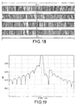
- the layout is of the type illustrated in FIG. 18.
- the lengths of the transducers are 264 periods (ie a length of approximately 4.75 mm).
- FIG. 7 The structure of FIG. 7 has been chosen for the resonators.
- Figure 18 illustrates the representative layout of the bridge electric realized with in two arms the first resonator and in two other arms the second resonator.
- the two E + inputs are connected in parallel by a wire and not a track.
- the filter is designed to operate with an impedance of 4,000 ⁇ with an inductor in parallel. Its transfer function is illustrated in figure 19.
Description
Le domaine de l'invention est celui des filtres à ondes acoustiques de surface présentant des performances très sélectives en fréquence, soit des largeurs de bande relativement faibles, avec de grandes qualités de rejection. Par ondes de surface, on entend ici non seulement des ondes de Rayleigh mais également tout type d'onde pouvant interagir avec des peignes d'électrodes à la surface d'un cristal ou à l'interface entre un cristal et une ou plusieurs couches d'un matériau quelconque. Les ondes dites pseudo acoustiques de surface, les ondes de surface transverses, ou les ondes de surface de type SSBW peuvent ainsi être considérées comme des ondes de surface et l'invention s'applique à ce type d'onde ainsi qu'à tout autre type d'onde vérifiant les conditions précédentes.The field of the invention is that of wave filters surface acoustics with very selective performance in frequency, i.e. relatively small bandwidths, with large rejection qualities. By surface waves here is meant not only Rayleigh waves but also any type of wave that can interact with combs of electrodes on the surface of a crystal or at the interface between a crystal and one or more layers of any material. Waves so-called surface pseudo acoustics, transverse surface waves, or SSBW type surface waves can thus be considered as surface waves and the invention applies to this type of wave as well as to any other type of wave satisfying the preceding conditions.
De manière générale, pour obtenir ce type de performances, on utilise des filtres avec des résonateurs constitués classiquement de transducteurs compris dans une cavité formée de deux réseaux périodiques, comme illustré en figure 1. Plus précisément, il s'agit de filtres multipôles obtenus en couplant plusieurs résonateurs. On cherche en effet à coupler le plus grand nombre de résonateurs puisque le nombre de résonateurs. couplés entre eux détermine en général le facteur de forme du filtre, c'est-à-dire le rapport entre la bande de rejection du filtre et sa bande passante. L'augmentation du nombre de résonateurs permet de se rapprocher d'un rapport de forme 1.In general, to obtain this type of performance, we uses filters with resonators conventionally made up of transducers included in a cavity formed by two periodic networks, as illustrated in figure 1. More specifically, they are multipole filters obtained by coupling several resonators. We are indeed trying to couple the greater number of resonators since the number of resonators. coupled together generally determines the form factor of the filter, i.e. the ratio between the filter rejection band and its pass band. The increase in the number of resonators makes it possible to approach a aspect ratio 1.
A l'heure actuelle, il est connu une configuration de filtre à ondes acoustiques de surface à deux pôles comportant une première paire de résonateurs IDT1 avec une fréquence centrale f1, une seconde paire de résonateurs IDT2 avec une fréquence centrale f2, l'ensemble des deux paires étant monté dans une structure de pont « équivalent électrique » comme illustré en figure 2. Ce type de configuration est décrit dans le brevet US 5 508 667.At present, a configuration of a two-pole surface acoustic wave filter is known, comprising a first pair of IDT 1 resonators with a center frequency f 1 , a second pair of IDT 2 resonators with a center frequency f 2 , the assembly of the two pairs being mounted in an “electric equivalent” bridge structure as illustrated in FIG. 2. This type of configuration is described in US Pat. No. 5,508,667.
L'intérêt de cette structure réside dans le fait que le produit des capacités statiques de la première paire est le même que le produit des capacités statiques de la seconde paire. Cet équilibrage permet d'assurer la rejection du filtre loin de sa fréquence centrale. En effet, loin de cette fréquence, les résonateurs sont électriquement équivalents à leurs capacités statiques et l'équilibrage permet qu'aucun signal ne passe. The interest of this structure lies in the fact that the product of static capabilities of the first pair is the same as the product of static capacities of the second pair. This balancing ensures the rejection of the filter far from its center frequency. Indeed, far from this frequency, the resonators are electrically equivalent to their capacities static and balancing allows no signal to pass.
Pour augmenter encore les performances des filtres à résonateurs il a été envisagé de cascader en série plusieurs structures à ponts « équivalent électrique ». Le plus souvent, on cascade des ponts identiques entre eux. L'inconvénient d'une telle structure réside dans le fait que cette cascade nécessite pour être efficace d'ajouter un élément électrique supplémentaire (inductance ou capacité). D'autre part, l'utilisation de plusieurs « ponts » cascadés représente un obstacle au niveau de l'implantation à l'intérieur du boítier du filtre.To further increase the performance of resonators it has been envisaged to cascade several structures in series at "electric equivalent" bridges. Most often, we cascade bridges identical to each other. The disadvantage of such a structure is that that this cascade requires to be effective to add an element additional electric (inductance or capacity). On the other hand, the use of several cascaded "bridges" represents an obstacle in terms of implantation inside the filter housing.
C'est pourquoi, l'invention propose une structure de filtre permettant de s'affranchir de la nécessité de l'inductance de couplage dans laquelle une unique structure de pont équivalent peut comprendre un grand nombre de pôles, par une mise en parallèle de différents résonateurs dans chaque bras du pont.This is why, the invention proposes a filter structure allowing to overcome the need for coupling inductance in which a single equivalent bridge structure can include a large number of poles, by putting different resonators in parallel in each arm of the bridge.
Plus précisément, l'invention a pour objet un filtre à ondes acoustiques de surface à N pôles, N étant un nombre pair supérieur ou égal à 3, et comportant un ensemble de résonateurs, caractérisé en ce que :
- les résonateurs sont couplés électriquement pour former un pont électrique à 4 bras ;
- 2 bras comportant deux sous-ensembles identiques E1 et E3 de N1 résonateurs chacun montés en parallèle ;
- 2 bras comportant deux sous-ensembles identiques E2 et E4 de N2 résonateurs chacun montés en parallèle ;
- avec N1 + N2 = N ;
- le produit de la capacité statique totale du sous-ensemble E1 par la capacité statique totale du sous-ensemble E3 étant sensiblement équivalent au produit de la capacité statique totale du sous-ensemble E2 par la capacité statique totale du sous-ensemble E4, de manière à équilibrer le pont électrique.
- the resonators are electrically coupled to form an electric bridge with 4 arms;
- 2 arms comprising two identical sub-assemblies E 1 and E 3 of N 1 resonators each mounted in parallel;
- 2 arms comprising two identical subsets E 2 and E 4 of N 2 resonators each mounted in parallel;
- with N 1 + N 2 = N;
- the product of the total static capacity of the subset E 1 by the total static capacity of the subset E 3 being substantially equivalent to the product of the total static capacity of the subset E 2 by the total static capacity of the subset E 4 , so as to balance the electric bridge.
Selon une première variante de . l'invention si N est pair N1 = N2 = N/2.According to a first variant of. the invention if N is even N 1 = N 2 = N / 2.
Selon une seconde variante de l'invention si N est impair N1 =(N-1)/2 et N2 = (N + 1) / 2.According to a second variant of the invention if N is odd N 1 = (N-1) / 2 and N 2 = (N + 1) / 2.
Selon la configuration de filtre proposée dans l'invention, la mise en parallèle des résonateurs nécessite des fils de connexion ou des pistes sur le substrat pour réaliser les ponts. Pour s'affranchir de cet obstacle. un mode préférentiel de l'invention consiste à ne pas faire physiquement la mise en parallèle des résonateurs mais plutôt à utiliser dans les différents bras du pont, des dispositifs à onde de surface se comportant comme plusieurs résonateurs branchés en parallèle.According to the filter configuration proposed in the invention, the setting in parallel resonators requires connection wires or tracks on the substrate to make the bridges. To overcome this obstacle. a preferred mode of the invention consists in not physically doing the parallel resonators but rather to use in different bridge arms, surface wave devices behaving like several resonators connected in parallel.
C'est pourquoi, le filtre à ondes acoustiques de surface peut avantageusement comprendre dans au moins un des bras du pont électrique, un unique dispositif à ondes de surface ayant une admittance équivalente à la mise en parallèle d'un sous-ensemble de résonateurs.Therefore, the surface acoustic wave filter can advantageously include in at least one of the arms of the bridge electric, a single surface wave device with admittance equivalent to paralleling a subset of resonators.
Notamment le filtre selon l'invention peut être caractérisé en ce qu'au moins un bras comporte une structure équivalente à plusieurs résonateurs montés en parallèle, ladite structure comportant deux réseaux d'électrodes interdigitées constitutifs de la partie transduction des résonateurs, lesdits réseaux étant connectés à deux bus de polarités différentes et comprenant m voies acoustiques insérées entre les deux bus, la ième voie acoustique possédant un pas pi d'électrodes, sur une longueur d'électrodes wi et 1 ≤ i ≤ m.In particular, the filter according to the invention can be characterized in that at least one arm has a structure equivalent to several resonators mounted in parallel, said structure comprising two networks of interdigitated electrodes constituting the transduction part of the resonators, said networks being connected to two buses of different polarities and comprising m acoustic channels inserted between the two buses, the i th acoustic channel having a pitch p i of electrodes, over a length of electrodes w i and 1 ≤ i ≤ m.
Selon une variante de l'invention, la ième voie acoustique peut comporter de chaque côté de la partie transduction deux réseaux réflecteurs.According to a variant of the invention, the i th acoustic channel may comprise on each side of the transduction part two reflective arrays.
Selon une variante de l'invention, le filtre à ondes acoustiques de surface peut comprendre dans au moins un des bras du pont électrique, une structure équivalente à au moins deux résonateurs montés en parallèle, ladite structure comportant deux réseaux d'électrodes interdigitées, lesdits réseaux étant connectés à un premier bus et à un second bus de polarités différentes, de manière à définir un transducteur présentant un axe central Z parallèle aux électrodes, lesdits réseaux comprenant une partie de leurs électrodes positionnées symétriquement par rapport à l'axe central, le transducteur comprenant également des électrodes positionnées symétriquement par rapport à l'axe central et connectées à des bus de polarités différentes, de manière à exciter des modes longitudinaux symétriques et des modes longitudinaux antisymétriques. Les réseaux d'électrodes peuvent ou non être insérés entre des réseaux réflecteursAccording to a variant of the invention, the acoustic wave filter of surface may include in at least one of the arms of the electric bridge, a structure equivalent to at least two resonators mounted in parallel, said structure comprising two networks of interdigitated electrodes, said networks being connected to a first bus and to a second bus of polarities different, so as to define a transducer having a central axis Z parallel to the electrodes, said networks comprising part of their electrodes positioned symmetrically with respect to the central axis, the transducer also including positioned electrodes symmetrically with respect to the central axis and connected to buses different polarities, so as to excite longitudinal modes symmetrical and asymmetric longitudinal modes. Networks electrodes may or may not be inserted between reflective arrays
Selon une autre variante de l'invention, le filtre à ondes acoustiques de surface comprend dans au moins un des bras du pont électrique, un résonateur de type DART avec des cellules de transduction intercalées entre des cellules de réflexion.According to another variant of the invention, the wave filter acoustic surface includes in at least one of the arms of the bridge electric, a DART type resonator with transduction cells sandwiched between reflection cells.
Avantageusement, le résonateur de type DART peut comprendre des cavités résonantes.Advantageously, the DART type resonator can include resonant cavities.
Lorsque le nombre de pôles est pair, la distance entre le centre de transduction d'une cellule de transduction et le centre de réflexion de la cellule de réflexion adjacente à ladite cellule de transduction peut de manière préférentielle être de l'ordre de (3 ± d) λ/8 + kλ/2, avec λ longueur d'onde correspondant à la fréquence centrale du filtre, d inférieur à 1 et k entier.When the number of poles is even, the distance between the center transduction cell of a transduction cell and the reflection center of the reflection cell adjacent to said transduction cell can preferentially be of the order of (3 ± d) λ / 8 + kλ / 2, with λ length wave corresponding to the center frequency of the filter, d less than 1 and k whole.
Enfin, selon une autre variante, le filtre à ondes acoustiques de surface est caractérisé en ce qu'il comprend la mise en série de plusieurs ensembles de résonateurs, dont au moins un ensemble de résonateurs correspond à ceux de l'invention.Finally, according to another variant, the acoustic wave filter of surface is characterized in that it comprises the placing in series of several sets of resonators, including at least one set of resonators corresponds to those of the invention.
L'invention sera mieux comprise et d'autres avantages apparaítront à la lecture de la description qui va suivre, donnée à titre non limitatif et grâce aux figures annexées parmi lesquelles :
- la figure 1 schématise un résonateur avec un transducteur inséré entre des réseaux réflecteurs ;
- la figure 2 illustre une configuration de filtre selon l'art connu, monté dans une structure de pont ;
- la figure 3 schématise une configuration générale de filtre à ondes acoustiques de surface selon l'invention ;
- la figure 4 illustre une implantation de filtre à ondes acoustiques de surface de l'art antérieur, à deux pôles ;
- la figure 5a schématise une implantation de filtre à ondes acoustiques de surface comprenant deux résonateurs montés en parallèle ;
- la figure 5b illustre un premier exemple d'implantation de résonateur équivalent à deux résonateurs montés en parallèle représentés en figure 5a ;
- la figure 6 illustre un deuxième exemple d'implantation de résonateur équivalent à deux résonateurs montés en parallèle, utilisant trois voies acoustiques ;
- la figure 7 illustre un troisième exemple d'implantation de résonateur équivalent à deux résonateurs montés en parallèle, utilisant deux voies acoustiques, mais décalés d'un pas pi ;
- la figure 8 illustre un quatrième exemple d'implantation de résonateur équivalent à deux résonateurs montés en parallèle, utilisant l'excitation de modes symétriques et de modes antisymétriques longitudinalement ;
- la figure 9 illustre l'admittance d'un exemple de transducteur de type DART, dans lequel le centre d'une cellule de transduction est séparé du centre d'une cellule de réflexion adjacente, d'une distance 3λ/8 ;
- la figure 10 illustre l'évolution de la conductance du même transducteur de type DART, dans lequel le centre d'une cellule de transduction est séparé du centre d'une cellule de réflexion adjacente, d'une distance variant de (3 - 0,4) λ /8 à (3 + 0,4) λ/8 ;
- la figure 11 illustre l'évolution de la susceptance du même transducteur de type DART, dans lequel le centre d'une cellule de transduction est séparé du centre d'une cellule de réflexion adjacente, d'une distance variant de (3 - 0,4) λ/8 à (3+0,4) λ/8 ;
- la figure 12 illustre la fonction de transfert pour un exemple de filtre selon l'invention, à 4 pôles, utilisant des DART ;
- la figure 13 illustre l'admittance d'un bras de pont électrique, comprenant un DART à deux modes utilisés dans un exemple de filtre selon l'invention, à 3 pôles ;
- la figure 14 illustre l'admittance du deuxième bras de pont électrique, comprenant un DART non pondéré, dans un exemple de filtre selon l'invention à 3 pôles ;
- la figure 15 illustre la fonction de transfert du même exemple de filtre selon l'invention, à 3 pôles, comprenant un résonateur à un mode dans un bras et un résonateur à deux modes dans l'autre bras ;
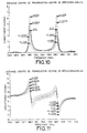
- la figure 16 illustre les conductances de deux résonateurs utilisés dans un exemple de filtre à 87 MHz selon l'invention utilisant des résonateurs du type illustré en figure 6 ;
- la figure 17 illustre les susceptances de deux résonateurs utilisés dans un exemple de filtre à 87 MHz selon l'invention utilisant des résonateurs du type illustré en figure 6 ;
- la figure 18 illustre l'implantation du filtre dont les caractéristiques sont données en figures 15, 16 et 17 ;
- la figure 19 illustre la fonction de transfert du filtre à 87 MHz réalisé selon l'invention.
- Figure 1 shows schematically a resonator with a transducer inserted between reflective arrays;
- FIG. 2 illustrates a filter configuration according to the prior art, mounted in a bridge structure;
- Figure 3 shows schematically a general configuration of surface acoustic wave filter according to the invention;
- FIG. 4 illustrates an implantation of a surface acoustic wave filter of the prior art, with two poles;
- FIG. 5a shows diagrammatically an implantation of a surface acoustic wave filter comprising two resonators mounted in parallel;
- FIG. 5b illustrates a first example of implantation of a resonator equivalent to two resonators mounted in parallel shown in FIG. 5a;
- FIG. 6 illustrates a second example of implantation of a resonator equivalent to two resonators mounted in parallel, using three acoustic channels;
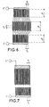
- FIG. 7 illustrates a third example of implantation of a resonator equivalent to two resonators mounted in parallel, using two acoustic channels, but offset by a pitch p i ;
- FIG. 8 illustrates a fourth example of implantation of a resonator equivalent to two resonators mounted in parallel, using the excitation of symmetrical modes and antisymmetric modes longitudinally;
- FIG. 9 illustrates the admittance of an example of a DART type transducer, in which the center of a transduction cell is separated from the center of an adjacent reflection cell, by a distance 3λ / 8;
- FIG. 10 illustrates the evolution of the conductance of the same DART type transducer, in which the center of a transduction cell is separated from the center of an adjacent reflection cell, by a distance varying from (3 - 0, 4) λ / 8 to (3 + 0.4) λ / 8;
- FIG. 11 illustrates the evolution of the susceptance of the same DART type transducer, in which the center of a transduction cell is separated from the center of an adjacent reflection cell, by a distance varying from (3 - 0, 4) λ / 8 to (3 + 0.4) λ / 8;
- FIG. 12 illustrates the transfer function for an example of a filter according to the invention, with 4 poles, using DARTs;
- FIG. 13 illustrates the admittance of an electric bridge arm, comprising a DART with two modes used in an example of a filter according to the invention, with 3 poles;
- FIG. 14 illustrates the admittance of the second electric bridge arm, comprising an unweighted DART, in an example of a filter according to the invention with 3 poles;
- FIG. 15 illustrates the transfer function of the same example of a filter according to the invention, with 3 poles, comprising a one-mode resonator in one arm and a two-mode resonator in the other arm;
- FIG. 16 illustrates the conductances of two resonators used in an example of an 87 MHz filter according to the invention using resonators of the type illustrated in FIG. 6;
- FIG. 17 illustrates the susceptances of two resonators used in an example of an 87 MHz filter according to the invention using resonators of the type illustrated in FIG. 6;
- FIG. 18 illustrates the installation of the filter, the characteristics of which are given in FIGS. 15, 16 and 17;
- FIG. 19 illustrates the transfer function of the 87 MHz filter produced according to the invention.
La configuration générale d'un filtre à ondes acoustiques de surface selon l'invention est schématisée en figure 3. Elle comporte une structure en forme de pont équivalent composée de quatre bras, chaque bras comprenant un ensemble de résonateurs montés en parallèle et relié à une entrée (E+, E-) et à une sortie (S+, S-). Les fréquences centrales des résonateurs f1, f2 ... fN correspondant aux pôles du filtre, ainsi que les « couplages » des différents résonateurs sont choisis pour obtenir la fonction de filtrage désirée.The general configuration of a surface acoustic wave filter according to the invention is shown diagrammatically in FIG. 3. It comprises an equivalent bridge-shaped structure composed of four arms, each arm comprising a set of resonators mounted in parallel and connected to a input (E +, E-) and to an output (S +, S-). The central frequencies of the resonators f 1 , f 2 ... f N corresponding to the poles of the filter, as well as the "couplings" of the different resonators are chosen to obtain the desired filtering function.
Pour bien comprendre le fonctionnement, il est nécessaire de s'intéresser de plus près au fonctionnement d'un résonateur. En général, près de la fréquence de résonance on peut considérer que le schéma équivalent d'un résonateur est donné par une capacité statique en parallèle à un circuit résonnant série à la fréquence fs.To fully understand the operation, it is necessary to take a closer look at the operation of a resonator. In general, near the resonant frequency we can consider that the equivalent diagram of a resonator is given by a static capacitance in parallel with a series resonant circuit at the frequency f s .
L'admittance du résonateur est donc (si l'on néglige la résistance
Rs) où f est la fréquence et ω la pulsation (ω = 2ηf)
On peut donc exprimer l'admittance d'un résonateur sous la forme
de la somme d'un terme capacitif lié à la capacité parallèle Cp et d'un terme
résonnant proportionnel à un coefficient a :
Le coefficient a (proportionnel à la capacité série du résonateur) détermine le « couplage » du mode de résonance considéré à l'accès électrique. Il sera dénommé par la suite couplage du mode.The coefficient a (proportional to the series capacity of the resonator) determines the “coupling” of the resonance mode considered at the access electric. It will hereinafter be referred to as mode coupling.
Un résonateur idéal sera donc caractérisé par la partie résonante
de son admittance qui est de la forme :

Le pôle à la fréquence f = fs (ou ω = ωs) n'est plus un vrai pôle puisqu'il est amorti. Autrement dit, les pertes transforment le pôle en f = fs en un pôle pour une fréquence complexe de partie réelle proche de fs et dont la partie imaginaire est d'autant plus forte que les pertes sont grandes. Un résonateur est donc caractérisé par une admittance comportant une résonance amortie ou non et donc présentant un pôle sur une fréquence proche de l'axe réel.The pole at the frequency f = f s (or ω = ω s ) is no longer a real pole since it is damped. In other words, the losses transform the pole in f = f s into a pole for a complex frequency of real part close to f s and whose imaginary part is all the stronger as the losses are large. A resonator is therefore characterized by an admittance comprising a damped resonance or not and therefore having a pole on a frequency close to the real axis.
Dans cette configuration, chacun des bras comporte deux résonateurs montés en parallèle. In this configuration, each of the arms has two resonators mounted in parallel.
Nous allons décrire l'invention en détail dans le cas d'un filtre à ondes acoustiques de surface à 4 pôles.We will describe the invention in detail in the case of a 4-pole surface acoustic waves.
Selon l'art antérieur connu, lorsque l'on cherche à implanter une structure de pont électrique à quatre bras, chaque bras comportant un résonateur, il est possible de concevoir une structure symétrique nécessaire à l'équilibrage du pont et donc aux qualités de rejection du filtre, avec une implantation du type de celle schématisée en figure 4.According to the known prior art, when one seeks to implant a four-arm electric bridge structure, each arm comprising a resonator, it is possible to design a symmetrical structure necessary the balance of the bridge and therefore the rejection qualities of the filter, with a layout of the type shown schematically in Figure 4.
Cette implantation présente l'avantage d'être symétrique même en ce qui concerne les capacités parasites par rapport au fond du boítier. Les surfaces des réseaux réflecteurs Ri sont les mêmes pour les deux ports + et -. D'autre part, la masse n'est pas connectée sur les filtres, puisque tous les réseaux sont branchés à un des ports d'entrée/sortie, ce qui permet de s'affranchir mieux des déséquilibres éventuels des circuits électriques de source et de charge.This layout has the advantage of being symmetrical even with regard to the parasitic capacities with respect to the bottom of the case. The surfaces of the reflector arrays R i are the same for the two ports + and -. On the other hand, the ground is not connected to the filters, since all the networks are connected to one of the input / output ports, which makes it possible to better overcome any imbalances in the electrical circuits of source and charge.
Cependant, la symétrie que l'on peut obtenir avec l'implantation décrite ci-dessus est plus difficile à obtenir lorsque l'on augmente le nombre de pôles.However, the symmetry that can be obtained with the implantation described above is more difficult to obtain when increasing the number of poles.
C'est pourquoi, l'invention propose de remplacer la mise en parallèle de plusieurs résonateurs par la réalisation de résonateurs équivalents à cette mise en parallèle et n'utilisant que deux bus de connexion et non plus quatre dans le cas de la mise en parallèle de deux résonateurs (deux entrées, deux sorties).This is why the invention proposes to replace the implementation parallel of several resonators by the realization of resonators equivalent to this paralleling and using only two bus connection and no longer four in the case of paralleling two resonators (two inputs, two outputs).
Il est notamment possible de réaliser un résonateur équivalent à deux résonateurs montés en parallèle, en séparant l'ouverture acoustique en deux voies et en interconnectant les électrodes de deux voies de manière à avoir sur chacune des deux voies la séquence correspondant à un des deux transducteurs. A titre d'exemple, la figure 5a illustre une implantation possible pour un montage de deux résonateurs montés en parallèleIt is in particular possible to produce a resonator equivalent to two resonators mounted in parallel, separating the acoustic opening in two ways and by interconnecting the electrodes of two ways so to have on each of the two channels the sequence corresponding to one of the two transducers. By way of example, FIG. 5a illustrates an installation possible for mounting two resonators mounted in parallel
La figure 5b illustre une implantation équivalente dans laquelle la première voie acoustique supérieure est réalisée à l'aide d'électrodes interdigitées au pas p1, la seconde voie acoustique inférieure est réalisée à l'aide d'électrodes interdigitées au pas p2. Les deux voies sont connectées électriquement par des métallisations m1, représentées symboliquement sur les figures. FIG. 5b illustrates an equivalent layout in which the first upper acoustic channel is produced using interdigitated electrodes at step p 1 , the second lower acoustic channel is produced using interdigitated electrodes at step p 2 . The two channels are electrically connected by metallizations m 1 , symbolically represented in the figures.
Les pas p1 et p2 régissent les fréquences de résonance du
résonateur équivalent aux deux résonateurs montés en parallèle. Les
dimensions w1 et w2 conditionnent -le couplage de ces résonateurs de
manière à obtenir les caractéristiques du filtre que l'on cherche à fabriquer.
Les figures 5a et 5b ne représentent que la partie transductrice des
résonateurs. Suivant l'art connu, les résonateurs comprennent en général
deux réseaux réflecteurs encadrant un transducteur. Les réseaux réflecteurs
sont omis sur la figure, mais peuvent être rajoutés sur chacune des voies.
Les réseaux de chacune des voies peuvent être connectés entre eux ou pas.
De façon préférentielle, on choisira pour les réseaux réflecteurs des
différentes voies des périodes proportionnelles aux périodes des
transducteurs. En d'autres termes, si pi et pj sont les périodes des deux
transducteurs et PRi et P'Rj les périodes des réseaux, on choisira :
De même, si Δ et Δ' sont les distances entre les réseaux
réflecteurs et les transducteurs on choisira préférentiellement :
Enfin, pour les filtres comportant plus que 4 pôles, on est amené à mettre plus que deux résonateurs en parallèle. On peut de la même manière que précédemment, utiliser plusieurs voies acoustiques et relier les métallisations des différentes voies entre elles pour réaliser la mise en parallèle.Finally, for filters with more than 4 poles, we are brought to put more than two resonators in parallel. We can in the same way so as before, use several acoustic channels and connect the metallizations of the different channels together to achieve the setting parallel.
Néanmoins, dans ce type de configuration, lorsque les deux voies acoustiques de dimensions w1 et w2 sont trop proches, il apparaít des phénomènes de diaphonie acoustiques parasites entre les voies.However, in this type of configuration, when the two acoustic channels of dimensions w 1 and w 2 are too close, it appears parasitic acoustic crosstalk between the channels.
C'est pourquoi, pour éliminer ce type de diaphonie, l'invention propose également une autre structure illustrée en figure 6. Pour cela, la voie centrale qui génère une excitation symétrique par rapport à l'axe horizontal et n'est donc couplée seulement qu'à des ondes de formes symétriques transversalement est insérée entre deux voies supérieure et inférieure correspondant globalement à l'une des voies acoustiques représentée en figure 5b. Les voies acoustiques supérieure et inférieure présentent les mêmes caractéristiques de dimension d'électrodes w1 = w3 et de pas d'électrodes p1 = p3. Ces deux voies génèrent à elles deux une excitation antisymétrique par rapport à l'axe horizontal puisque les électrodes en regard pour les deux voies sont reliées à des potentiels opposés. Ces deux voies ne sont donc couplées qu'à des ondes de formes antisymétriques transversalement et il ne peut donc exister aucune diaphonie entre la voie centrale et les voies extérieures. Autrement dit, du fait de la connexion des électrodes en regard des voies extrêmes au bus opposé, la diaphonie entre la voie centrale et la voie haute s'additionne en opposition de phase, et donc s'annule avec la diaphonie entre la voie centrale et la voie basse. Pour obtenir la compensation des phénomènes de couplage, les électrodes connectées au bus E+ sont mises en regard des électrodes connectées au bus E- sur les voies extrêmes.This is why, to eliminate this type of crosstalk, the invention also proposes another structure illustrated in FIG. 6. For this, the central channel which generates a symmetrical excitation with respect to the horizontal axis and is therefore only coupled that waves of symmetrical shapes transversely is inserted between two upper and lower channels corresponding overall to one of the acoustic channels shown in Figure 5b. The upper and lower acoustic channels have the same characteristics of electrode size w 1 = w 3 and of electrode pitch p 1 = p 3 . These two paths together generate an asymmetric excitation with respect to the horizontal axis since the facing electrodes for the two paths are connected to opposite potentials. These two channels are therefore only coupled to waves of antisymmetrical shapes transversely and there can therefore be no crosstalk between the central channel and the external channels. In other words, due to the connection of the electrodes facing the extreme channels to the opposite bus, the crosstalk between the central channel and the high channel is added in phase opposition, and therefore is canceled with the crosstalk between the central channel and the low way. To obtain compensation for coupling phenomena, the electrodes connected to the E + bus are placed opposite the electrodes connected to the E- bus on the extreme channels.
Les deux fréquences de résonance recherchées, pour reconstituer deux résonateurs montés en parallèle peuvent aussi être obtenues grâce à l'écart de vitesse des modes transversaux symétriques et antisymétriques.The two resonance frequencies sought, for reconstruct two resonators mounted in parallel can also be obtained thanks to the speed difference of the symmetrical transverse modes and antisymmetric.
Dans ce cas, il est également possible de réaliser une structure dans laquelle les pas p1 et p2 sont égaux. Dans ce cas particulier, il devient même possible de réaliser une structure à deux voies acoustiques comme illustré en figure 7. En décalant d'une distance p1 les électrodes des deux voies, on parvient à compenser de même qu'explicité ci-dessus, les phénomènes de couplage parasite, puisque l'on parvient à mettre en regard des électrodes connectées au bus E+ avec des électrodes connectées au bus E-. Dans cette configuration, la voie centrale devient alignée avec une des voies extrêmes.In this case, it is also possible to produce a structure in which the steps p 1 and p 2 are equal. In this particular case, it even becomes possible to produce a structure with two acoustic channels as illustrated in FIG. 7. By shifting the electrodes of the two channels by a distance p 1 , it is possible to compensate, as explained above, the parasitic coupling phenomena, since it is possible to compare the electrodes connected to the bus E + with electrodes connected to the bus E-. In this configuration, the central channel becomes aligned with one of the extreme channels.
Selon une autre variante de l'invention, il est possible de réaliser une structure équivalente à deux résonateurs montés en parallèle, en paramétrant le nombre de modes longitudinaux créés dans le résonateur.According to another variant of the invention, it is possible to carry out a structure equivalent to two resonators mounted in parallel, in setting the number of longitudinal modes created in the resonator.
En effet, de manière générale, un résonateur est un transducteur placé entre deux réseaux réflecteurs. Suivant la période du réseau et celle du transducteur, et suivant l'écartement entre réseaux et transducteur, on est en présence de plusieurs modes longitudinaux. Le couplage d'un mode dépend de l'intégrale de recouvrement de la pondération du transducteur sur l'amplitude du mode dans la cavité. De manière générale, on est en présence de modes symétriques et antisymétriques. Il est possible de pondérer le transducteur, de manière à obtenir les couplages voulus avec les modes symétriques et antisymétriques.In general, a resonator is a transducer placed between two reflecting arrays. Depending on the network period and that of the transducer, and depending on the spacing between networks and transducer, we is in the presence of several longitudinal modes. The coupling of a mode depends on the integral of the transducer weighting on the amplitude of the mode in the cavity. In general, we are in presence of symmetric and antisymmetric modes. It is possible to weight the transducer, so as to obtain the desired couplings with symmetric and antisymmetric modes.
La figure 8 illustre un exemple de résonateur dans lequel il est possible d'exciter à la fois les modes longitudinaux symétriques et les modes longitudinaux antisymétriques.FIG. 8 illustrates an example of a resonator in which it is possible to excite both the symmetrical longitudinal modes and the modes longitudinal asymmetric.
Pr représente le pas des éléments constitutifs des réseaux 1 et 2. Pt représente le pas des électrodes du transducteur. Δ représente l'écartement entre le transducteur et un réseau. Le transducteur présente une dissymétrie par rapport à l'axe Z centré au niveau du transducteur.P r represents the pitch of the constituent elements of networks 1 and 2. P t represents the pitch of the electrodes of the transducer. Δ represents the distance between the transducer and a network. The transducer has an asymmetry with respect to the Z axis centered at the level of the transducer.
Suivant les périodes Pr et Pt, la distance Δ et le nombre de périodes du transducteur, la cavité de résonance va avoir plusieurs fréquences de résonance correspondant à différentes répartitions longitudinales de l'énergie dans la cavité. En choisissant de manière appropriée l'excitation, c'est-à-dire la séquence d'électrodes du transducteur, on peut exciter les modes longitudinaux symétriques et les modes longitudinaux antisymétriques. La pondération du transducteur peut être décomposée en deux parties. La partie symétrique (par rapport à l'axe z) de la pondération excitera les modes longitudinaux symétriques alors que la partie antisymétrique (par rapport à l'axe z) excitera les modes longitudinaux antisymétriques. L'intégrale de recouvrement de la partie symétrique (ou antisymétrique) de la pondération sur l'amplitude des modes symétriques (antisymétriques) sera reliée au couplage des modes symétriques (antisymétriques).According to the periods P r and P t , the distance Δ and the number of periods of the transducer, the resonance cavity will have several resonance frequencies corresponding to different longitudinal distributions of the energy in the cavity. By appropriately choosing the excitation, that is to say the sequence of electrodes of the transducer, it is possible to excite the symmetrical longitudinal modes and the antisymmetric longitudinal modes. The weighting of the transducer can be broken down into two parts. The symmetric part (with respect to the z axis) of the weighting will excite the symmetrical longitudinal modes while the asymmetric part (with respect to the z axis) will excite the longitudinal asymmetric modes. The integral of the symmetrical (or antisymmetric) part of the weighting on the amplitude of the symmetric (antisymmetric) modes will be linked to the coupling of the symmetric (antisymmetric) modes.
Le transducteur représenté en figure 8, n'est ni entièrement symétrique, ni entièrement antisymétrique et permet l'excitation à la fois de modes symétriques et de modes antisymétriques de manière à reconstituer le couplage entre modes, et ainsi l'équivalence avec deux résonateurs montés en parallèle.The transducer shown in Figure 8, is neither entirely symmetrical, nor entirely antisymmetrical and allows the excitation of both symmetrical modes and antisymmetric modes so as to reconstruct coupling between modes, and thus equivalence with two resonators mounted in parallel.
Selon une autre variante de l'invention, le filtre à ondes acoustiques de surface, comprend des transducteurs de type DART According to another variant of the invention, the wave filter surface acoustic, includes DART transducers
Ce type de transducteur, décrit dans la demande de brevet publiée 2 702 899, est réalisé en intercalant dans un transducteur des cellules dites de transduction et des cellules dites de réflexion et en positionnant les cellules entre elles de manière à avoir remis en phase des ondes émises avec les ondes réfléchies dans la direction utile et avoir opposition de phase dans l'autre direction. Pour les substrats habituels, la distance entre centre de transduction et centre de réflexion doit être de 3λ/8 pour que les phases soient correctes. Plus généralement, un DART peut être considéré comme un transducteur dans lequel sont distribuées des électrodes conçues pour qu'existent à l'intérieur du transducteur une fonction de transduction, et une fonction de réflexion et tel que le transducteur ait une direction privilégiée. Il a été montré dans la demande de brevet publiée 2 702 899 qu'il était avantageux de réaliser des cavités résonantes à l'intérieur du DART, une cavité résonante étant réalisée en changeant le signe de la fonction de réflexion.This type of transducer, described in the patent application published 2,702,899, is achieved by inserting in a transducer so-called transduction cells and so-called reflection cells and in positioning the cells together so as to have re-phased waves emitted with waves reflected in the useful direction and have phase opposition in the other direction. For usual substrates, the distance between transduction center and reflection center must be 3λ / 8 so that the phases are correct. More generally, a DART can be considered as a transducer in which are distributed electrodes designed so that inside the transducer there is a transduction function, and a reflection function and such that the transducer has a preferred direction. It was shown in the application of published patent 2,702,899 that it was advantageous to produce cavities resonant inside the DART, a resonant cavity being made of changing the sign of the reflection function.
Il est connu que dans la cas d'un DART non pondéré, c'est-à-dire comportant des fonctions de réflexion et de transduction constantes et suffisamment long pour que son coefficient de réflexion global soit proche de 1, deux modes existent aux fréquences de début et de fin de la bande d'arrêt des réflecteurs. Dans le cas où l'écart de phase entre réflexion et transduction correspond à une remise en phase des ondes émises et réfléchies dans la direction utile, c'est-à-dire en général dans le cas où la distance entre centre de transduction et centre de réflexion est de 3λ/8, les deux modes sont excités de manière identique et la conductance du transducteur est symétrique en fréquence. Par exemple, la figure 9 montre l'admittance d'un transducteur DART de longueur 200 λ à 109.3 MHz. L'épaisseur de métallisation choisie est de 0,7 µm et un réflecteur de largeur 3λ/8 est utilisé par longueur d'onde. Le transducteur est « idéal » c'est-à-dire que la distance centre de transduction/centre de réflexion est de 3λ/8.It is known that in the case of an unweighted DART, that is to say with constant reflection and transduction functions and long enough for its overall reflection coefficient to be close to 1, two modes exist at the start and end frequencies of the stop band reflectors. In the case where the phase difference between reflection and transduction corresponds to a rephasing of the waves emitted and reflected in the useful direction, that is to say in general in the case where the distance between transduction center and reflection center is 3λ / 8, the two modes are excited in the same way and the conductance of the transducer is frequency symmetrical. For example, Figure 9 shows the admittance of a DART transducer of length 200 λ at 109.3 MHz. The chosen metallization thickness is 0.7 µm and a width reflector 3λ / 8 is used per wavelength. The transducer is "ideal" that is to say that the distance between the transduction center and the reflection center is 3λ / 8.
Les figures 10 et 11 montrent l'évolution des conductances et susceptances lorsque la distance : centre de transduction/centre de réflexion varie de 3λ/8-0.05λ à 3λ/8+0.05λ. On constate qu'on est toujours en présence des deux mêmes modes mais que leur importance relative varie suivant la distance. D'autre part, lorsque l'on change le signe du décalage, on obtient la même conductance à une symétrie près. Dans le cas d'un filtre à 4 pôles, il est en général intéressant sur un bras du pont électrique d'utiliser des modes tels que leurs couplages soient environ dans un rapport 2. A titre d'exemple, le filtre selon l'invention peut comprendre dans un de ses bras un DART utilisant un décalage de -0.025 λ et sur l'autre bras un DART utilisant un décalage de +0.025 λ. De manière à avoir quatre fréquences de résonance distinctes, on a décalé en fréquence d'environ 250 kHz vers le bas le transducteur utilisant un décalage de -0.025λ. La figure 12 montre la fonction de transfert obtenue pour le filtre accordé électriquement.Figures 10 and 11 show the evolution of the conductances and susceptibility when distance: transduction center / reflection center varies from 3λ / 8-0.05λ to 3λ / 8 + 0.05λ. We see that we are still in presence of the same two modes but that their relative importance varies depending on the distance. On the other hand, when we change the sign of the offset, the same conductance is obtained except for symmetry. In the case of a filter with 4 poles, it is generally interesting on an arm of the electric bridge to use modes such that their couplings are approximately in a ratio 2. By way of example, the filter according to the invention can comprise, in one of his arms a DART using an offset of -0.025 λ and on the other arm a DART using an offset of +0.025 λ. So as to have four distinct resonant frequencies, we shifted in frequency by about 250 kHz down the transducer using an offset of -0.025λ. The figure 12 shows the transfer function obtained for the tuned filter electrically.
Selon un autre exemple utilisant des DART, un filtre 3 pôles peut être obtenu en utilisant un résonateur à un mode dans un des bras et un résonateurs à deux modes dans l'autre bras. Le résonateurs à deux modes utilisé dans l'exemple est un DART non pondéré avec une distance réflexion transduction de 3λ/8. Le DART a 400 longueurs d'ondes de long. L'épaisseur de métallisation choisie est de 0.35 µm et un réflecteur de largeur 3λ/8 est utilisé par longueur d'onde. La fréquence centrale est de 109.8 MHz. La figure 13 montre l'admittance du DART avec ses deux modes à l'entrée et à la sortie de la bande d'arrêt. Pour l'autre bras du pont électrique, on a choisi d'utiliser un DART de même longueur (et donc de même capacité statique) et résonant à la fréquence centrale. La figure 14 montre l'admittance du DART non pondéré, inclus dans l'autre bras du pont électrique. Ceci a été obtenu en insérant un changement de signe de la fonction de réflexion au centre du transducteur. On a alors un mode résonance unique.According to another example using DARTs, a 3-pole filter can be obtained using a one mode resonator in one of the arms and a dual-mode resonators in the other arm. The two-mode resonators used in the example is an unweighted DART with a reflection distance 3λ / 8 transduction. The DART has 400 wavelengths long. The chosen metallization thickness is 0.35 µm and a reflector of width 3λ / 8 is used per wavelength. The center frequency is 109.8 MHz. Figure 13 shows the admittance of DART with its two modes at the entrance and exit of the stop lane. For the other arm of the bridge electric, we chose to use a DART of the same length (and therefore same static capacity) and resonating at the center frequency. Figure 14 shows the admittance of the unweighted DART, included in the other arm of the bridge electric. This was achieved by inserting a sign change from the reflection function in the center of the transducer. We then have a mode unique resonance.
La fonction de transfert obtenue pour le filtre à 3 pôles est donnée figure 15The transfer function obtained for the 3-pole filter is given figure 15
Il s'agit d'un filtre à bande passante d'environ 300 kHz dans un boítier très petit (7 mm x 5 mm) avec un nombre de pôles N égal 4It is a bandwidth filter of around 300 kHz in a very small box (7 mm x 5 mm) with an equal number of poles N 4
Pour atteindre ce faible encombrement au niveau du boítier, les
résonateurs utilisés ne comportent pas de réseaux réflecteurs et se
réduisent donc à de simples transducteurs à deux électrodes par longueurs
d'onde. L'implantation est du type de celle illustrée en figure 18. Les
longueurs des transducteurs sont de 264 périodes (soit une longueur de
4,75 mm environ). En négligeant les pertes, les admittances des branches
sont données à peu près par :

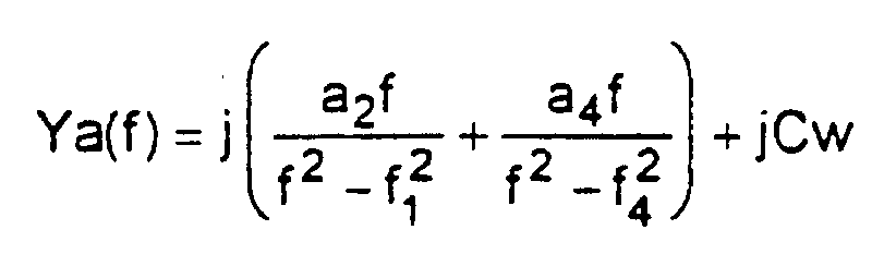
On obtient les caractéristiques de conductances et de susceptances, en fonction de la fréquence respectivement illustrées en figures 16 et 17.We obtain the characteristics of conductances and susceptances, as a function of the frequency respectively illustrated in Figures 16 and 17.
Pour réaliser les admittances voulues des résonateurs, on choisit une ouverture et une épaisseur de métallisation permettant d'obtenir un écart de 310 kHz entre les fréquences de résonance du premier mode transverse symétrique et du premier mode transverse antisymétrique, soit une épaisseur de métallisation de 0,8 µm et une ouverture de transducteur d'environ 300 µm.To achieve the desired admittances of the resonators, we choose an opening and a metallization thickness making it possible to obtain a difference of 310 kHz between the resonance frequencies of the first mode symmetrical transverse and the first antisymmetrical transverse mode, that is to say 0.8 µm metallization thickness and transducer opening about 300 µm.
La structure de la figure 7 a été choisie pour les résonateurs.The structure of FIG. 7 has been chosen for the resonators.
Ainsi, pour les deux résonateurs, on a les caractéristiques
suivantes :
Les périodes de ces deux résonateurs sont déterminées de
manière à caler correctement les fréquences entre elles à savoir
approximativement :
La figure 18 illustre l'implantation représentative du pont électrique réalisé avec dans deux bras le premier résonateur et dans deux autres bras le second résonateur.Figure 18 illustrates the representative layout of the bridge electric realized with in two arms the first resonator and in two other arms the second resonator.
Pour des raisons d'encombrement, les deux entrées E+ sont connectées en parallèle par un fil et non une piste.For reasons of space, the two E + inputs are connected in parallel by a wire and not a track.
Le filtre est conçu pour fonctionner avec une impédance de 4 000 Ω avec une inductance en parallèle. Sa fonction de transfert est illustrée en figure 19.The filter is designed to operate with an impedance of 4,000 Ω with an inductor in parallel. Its transfer function is illustrated in figure 19.
Claims (15)
- Surface-acoustic-wave filter with N poles, N being a number greater than or equal to 3, and comprising a set of resonators, characterized in that:the resonators are electrically coupled to form a 4-arm electrical bridge;2 arms comprising a first and a third identical sub-assembly (E1 and E3) of N1 parallel-connected resonators;2 arms comprising a second and fourth identical sub-assembly (E2 and E4) of N2 parallel-connected resonators;with N1 + N2 = N;the product of the static capacitance of the first sub-assembly (E1) multiplied by the static capacitance of the third sub-assembly (E3) being substantially equivalent to the product of the static capacitance of the second sub-assembly (E2) multiplied by the static capacitance of the fourth sub-assembly (E4), so as to balance the electrical bridge.
- Surface-acoustic-wave filter according to Claim 1, characterized in that N is an even number and N1 = N2 = N/2.
- Surface-acoustic-wave filter according to Claim 1, characterized in that N is an odd number and N1 = (N-1)/2 and N2 = (N + 1)/2.
- Surface-acoustic-wave filter according to one of the Claims 1 to 3, characterized in that at least one arm comprises a single surface wave device having an admittance equivalent to the parallel connection of a subassembly of resonators.
- Surface-acoustic-wave filter according to one of the Claims 1 to 4, characterized in that at least one arm comprises a structure equivalent to several parallel-connected resonators, said structure comprising two arrays of interdigitated electrodes constituting the transduction part of the resonators, said arrays being connected to two buses with different polarities and comprising m acoustic channels inserted between the two buses, the ith acoustic channel possessing a pitch pi of electrodes over a length of electrodes wi and 1 ≤ i ≤ m.
- Surface-acoustic-wave filter according to Claim 5, characterized in that the ith acoustic channel comprises two reflective arrays on each side of the transduction part.
- Surface-acoustic-wave filter according to one of the Claims 5 or 6, characterized in that the two consecutive acoustic channels are connected to each other by metallizations mi, connecting the electrodes separated by a pitch pi to the electrodes separated by a pitch pi+1.
- Surface-acoustic-wave filter according to one of the Claims 5 to 7, characterized in at least one arm comprises a structure equivalent to two parallel-connected resonators and said structure comprises an upper acoustic channel and a lower acoustic channel with an electrode pitch p1 and an electrode length w1, a central acoustic channel with an electrode pitch p2 and an electrode length w2, the electrodes of the array of electrodes connected to the first bus of the upper acoustic channel being aligned with the electrodes of the array of electrodes connected to the second bus of the lower acoustic channel.
- Surface-acoustic-wave filter according to one of the Claims 5 to 7, characterized in that the pitches p1 and p2 are equal and in that the structure comprises two acoustic channels, the electrodes of each of the arrays of electrodes being offset by a distance p1 between the two acoustic channels.
- Surface-acoustic-wave filter according to one of the Claims 1 to 3, characterized in that at least one of the arms comprises a structure equivalent to at least two parallel-connected resonators, said structure comprising two interdigitated electrode arrays, said arrays being connected to a first bus and a second bus with different polarities so as to define a transducer having a central axis (Z) parallel to the electrodes, said transducer comprising electrodes positioned symmetrically with respect to the central axis and connected to the first bus and comprising electrodes positioned symmetrically with respect to the central axis and connected to the second bus with opposite polarity, so as to excite symmetrical longitudinal modes and antisymmetrical longitudinal modes.
- Surface-acoustic-wave filter according to Claim 10, characterized in that the transducer is inserted between two reflector arrays.
- Surface-acoustic-wave filter according to one of the Claims 1 to 4, characterized in that at least one of the arms comprises a DART type resonator with transduction cells interposed between reflection cells.
- Surface-acoustic-wave filter according to Claim 12, characterized in that the DART type resonator comprises resonant cavities.
- Surface-acoustic-wave filter according to one of the Claims 12 or 13, characterized in that the number of poles is an even number and in that the distance between the transduction centre of a transduction cell and the reflection centre of a reflection cell adjacent to said transduction cell is of the order of (3 ± d)λ/8 + kλ/2, with λ being the wavelength corresponding to the centre frequency or the filter, d being smaller than 1 and k being an integer.
- Surface-acoustic-wave filter characterized in that it comprises the series connection of several sets of resonators, of which at least one set of resonators complies with one of the Claims 1 to 14.
Applications Claiming Priority (3)
| Application Number | Priority Date | Filing Date | Title |
|---|---|---|---|
| FR9801419 | 1998-02-06 | ||
| FR9801419A FR2774826B1 (en) | 1998-02-06 | 1998-02-06 | SURFACE ACOUSTIC WAVE RESONATOR FILTER |
| PCT/FR1999/000214 WO1999040678A1 (en) | 1998-02-06 | 1999-02-02 | Filter with surface acoustic wave resonators |
Publications (2)
| Publication Number | Publication Date |
|---|---|
| EP1053593A1 EP1053593A1 (en) | 2000-11-22 |
| EP1053593B1 true EP1053593B1 (en) | 2002-05-08 |
Family
ID=9522684
Family Applications (1)
| Application Number | Title | Priority Date | Filing Date |
|---|---|---|---|
| EP99901689A Expired - Lifetime EP1053593B1 (en) | 1998-02-06 | 1999-02-02 | Filter with surface acoustic wave resonators |
Country Status (10)
| Country | Link |
|---|---|
| US (1) | US6344705B1 (en) |
| EP (1) | EP1053593B1 (en) |
| JP (1) | JP2002503049A (en) |
| KR (1) | KR20010040543A (en) |
| CN (1) | CN1144361C (en) |
| CA (1) | CA2319690A1 (en) |
| DE (1) | DE69901426T2 (en) |
| FR (1) | FR2774826B1 (en) |
| HK (1) | HK1035969A1 (en) |
| WO (1) | WO1999040678A1 (en) |
Families Citing this family (20)
| Publication number | Priority date | Publication date | Assignee | Title |
|---|---|---|---|---|
| DE10026074B4 (en) * | 2000-05-25 | 2010-02-18 | Epcos Ag | Recursive SAW filter with a small chip length |
| JP3863712B2 (en) * | 2000-09-06 | 2006-12-27 | 株式会社日立製作所 | Surface acoustic wave resonator |
| JP3824498B2 (en) * | 2000-09-28 | 2006-09-20 | 富士通株式会社 | Surface acoustic wave filter |
| US6924715B2 (en) * | 2002-02-12 | 2005-08-02 | Nortel Networks Limited | Band reject filters |
| JP4079658B2 (en) * | 2002-03-05 | 2008-04-23 | 株式会社リコー | Circuit for generating binarized wobble signal, write clock generating circuit, method for generating binarized wobble signal, write clock generating method, and optical disc apparatus |
| FR2837636B1 (en) * | 2002-03-19 | 2004-09-24 | Thales Sa | LITHIUM TANTALATE INTERFACE ACOUSTIC WAVE DEVICE |
| JP3963824B2 (en) * | 2002-11-22 | 2007-08-22 | 富士通メディアデバイス株式会社 | FILTER ELEMENT, FILTER APPARATUS HAVING THE SAME, DEMUX AND HIGH FREQUENCY |
| DE10319554B4 (en) * | 2003-04-30 | 2018-05-09 | Snaptrack, Inc. | Bulk acoustic wave device with coupled resonators |
| FR2864618B1 (en) * | 2003-12-24 | 2006-03-03 | Temex Sa | REMOTE TEMPERATURE OR TEMPERATURE AND PRESSURE SENSOR |
| JP4586404B2 (en) * | 2004-04-28 | 2010-11-24 | ソニー株式会社 | Filter device and transceiver |
| JP4800026B2 (en) * | 2005-12-16 | 2011-10-26 | 三星電子株式会社 | Complex coefficient transversal filter and frequency converter |
| DE202006007423U1 (en) * | 2006-05-09 | 2007-09-13 | EKATO Rühr- und Mischtechnik GmbH | stirrer |
| JP5237138B2 (en) * | 2009-01-27 | 2013-07-17 | 太陽誘電株式会社 | Filters, duplexers, communication modules |
| JP6135184B2 (en) * | 2013-02-28 | 2017-05-31 | セイコーエプソン株式会社 | Ultrasonic transducer device, head unit, probe, and ultrasonic imaging apparatus |
| JP6160120B2 (en) * | 2013-02-28 | 2017-07-12 | セイコーエプソン株式会社 | Ultrasonic transducer device, ultrasonic measurement device, head unit, probe, and ultrasonic imaging device |
| US10574203B2 (en) | 2015-07-28 | 2020-02-25 | Qorvo Us, Inc. | Bonded wafers and surface acoustic wave devices using same |
| US10128814B2 (en) | 2016-01-28 | 2018-11-13 | Qorvo Us, Inc. | Guided surface acoustic wave device providing spurious mode rejection |
| US10084427B2 (en) | 2016-01-28 | 2018-09-25 | Qorvo Us, Inc. | Surface acoustic wave device having a piezoelectric layer on a quartz substrate and methods of manufacturing thereof |
| US11206007B2 (en) | 2017-10-23 | 2021-12-21 | Qorvo Us, Inc. | Quartz orientation for guided SAW devices |
| US20230061645A1 (en) * | 2021-09-01 | 2023-03-02 | RF360 Europe GmbH | Electroacoustic filter with low phase delay for multiplexed signals |
Family Cites Families (19)
| Publication number | Priority date | Publication date | Assignee | Title |
|---|---|---|---|---|
| US3435259A (en) * | 1965-05-13 | 1969-03-25 | Us Army | Filter circuit |
| FR2250102B1 (en) | 1973-10-31 | 1976-10-01 | Thomson Csf | |
| FR2266394B1 (en) | 1974-03-26 | 1981-02-27 | Thomson Csf | |
| FR2326094A1 (en) | 1975-09-26 | 1977-04-22 | Thomson Csf | TWO-DIMENSIONAL OPTICAL IMAGE READING DEVICE, USING ELASTIC SURFACE WAVES |
| FR2365138A1 (en) | 1976-09-17 | 1978-04-14 | Thomson Csf | CODING SYSTEM BY MODULATION OF A LIGHT SIGNAL |
| GB2197559B (en) * | 1986-08-22 | 1990-03-28 | Clarion Co Ltd | Bias voltage circuit for a convolver |
| JPS6352509A (en) * | 1986-08-22 | 1988-03-05 | Clarion Co Ltd | Circuit for applying optimum to convolver |
| FR2628265B1 (en) | 1987-03-06 | 1990-12-21 | Thomson Csf | DIRECTIVE ANTENNA WITH MULTIPLE TRANSDUCERS IN PARTICULAR FOR SONAR |
| FR2612711A1 (en) | 1987-03-19 | 1988-09-23 | Thomson Csf | METHOD FOR CORRECTING A SURFACE WAVE DEVICE, IN PARTICULAR FOR A DISPERSIVE FILTER |
| US5264751A (en) | 1989-10-20 | 1993-11-23 | Thomson-Csf | Unilateral surface wave transducer |
| US5028895A (en) * | 1990-05-29 | 1991-07-02 | Motorola, Inc. | Notch filter for reducing clock signal feedthrough effects in an acoustic charge transport device |
| FR2682833B1 (en) | 1991-10-18 | 1993-12-03 | Thomson Csf | SURFACE WAVE FILTER WITH FOLDED ACOUSTIC PATH. |
| US5703427A (en) | 1993-03-19 | 1997-12-30 | Thomson-Csf | Surface-wave distributed acoustic reflection transducer and filter including such a transducer |
| GB2280806B (en) * | 1993-08-04 | 1997-10-08 | Advanced Saw Prod Sa | Saw filter |
| US5847626A (en) * | 1994-02-22 | 1998-12-08 | Matsushita Electric Industrial Co., Ltd. | Balanced-type surface acoustic wave lattice filter |
| FR2739232B1 (en) | 1995-09-26 | 1997-10-24 | Thomson Csf | SURFACE ACOUSTIC WAVE FILTER USING THE COUPLING OF THREE ACOUSTIC CHANNELS |
| FR2740908B1 (en) | 1995-11-07 | 1997-11-28 | Thomson Csf | DIFFERENTIAL SURFACE ACOUSTIC WAVE TRANSDUCER |
| GB2312109B (en) * | 1996-03-29 | 2000-08-02 | Advanced Saw Prod Sa | Acoustic wave filter |
| FR2762458B1 (en) | 1997-04-18 | 1999-07-09 | Thomson Csf | SURFACE ACOUSTIC WAVE DEVICE HAVING PROXIMITY COUPLING WITH DIFFERENTIAL INPUTS / OUTPUTS |
-
1998
- 1998-02-06 FR FR9801419A patent/FR2774826B1/en not_active Expired - Fee Related
-
1999
- 1999-02-02 US US09/601,321 patent/US6344705B1/en not_active Expired - Fee Related
- 1999-02-02 WO PCT/FR1999/000214 patent/WO1999040678A1/en not_active Application Discontinuation
- 1999-02-02 JP JP2000530978A patent/JP2002503049A/en active Pending
- 1999-02-02 CA CA002319690A patent/CA2319690A1/en not_active Abandoned
- 1999-02-02 CN CNB998025666A patent/CN1144361C/en not_active Expired - Fee Related
- 1999-02-02 DE DE69901426T patent/DE69901426T2/en not_active Expired - Lifetime
- 1999-02-02 KR KR1020007008408A patent/KR20010040543A/en not_active Application Discontinuation
- 1999-02-02 EP EP99901689A patent/EP1053593B1/en not_active Expired - Lifetime
-
2001
- 2001-09-15 HK HK01106536A patent/HK1035969A1/en not_active IP Right Cessation
Also Published As
| Publication number | Publication date |
|---|---|
| HK1035969A1 (en) | 2001-12-14 |
| DE69901426D1 (en) | 2002-06-13 |
| FR2774826A1 (en) | 1999-08-13 |
| FR2774826B1 (en) | 2000-05-05 |
| US6344705B1 (en) | 2002-02-05 |
| KR20010040543A (en) | 2001-05-15 |
| EP1053593A1 (en) | 2000-11-22 |
| CN1289478A (en) | 2001-03-28 |
| DE69901426T2 (en) | 2003-01-16 |
| JP2002503049A (en) | 2002-01-29 |
| CN1144361C (en) | 2004-03-31 |
| WO1999040678A1 (en) | 1999-08-12 |
| CA2319690A1 (en) | 1999-08-12 |
Similar Documents
| Publication | Publication Date | Title |
|---|---|---|
| EP1053593B1 (en) | Filter with surface acoustic wave resonators | |
| CA2121477C (en) | Surface wave filter having a folded acoustic path | |
| EP0872954B1 (en) | Surface acoustic wave device with proximity coupling and with differential inputs and outputs | |
| EP3996275A2 (en) | Electromechanical device with adjustable resonance frequency | |
| FR2834593A1 (en) | PIEZOELECTRIC RESONATOR AND PIEZOELECTRIC FILTER, DUPLEXER AND COMMUNICATION APPARATUS INCLUDING THE SAME | |
| FR2821997A1 (en) | SURFACE ACOUSTIC WAVE FILTER | |
| FR2739232A1 (en) | SURFACE ACOUSTIC WAVE FILTER USING THE COUPLING OF THREE ACOUSTIC CHANNELS | |
| WO1994007307A1 (en) | Unidirectional wave transducer | |
| EP2509221B1 (en) | Device using a resonator based filter | |
| EP0982859B1 (en) | Acoustic filter with two different channels and rejection compensation | |
| EP2901551B1 (en) | Electroacoustic device comprising a controllable phononique crystal using piezoelectric elements | |
| WO1993013595A1 (en) | Surface wave filter | |
| FR3079101A1 (en) | TRANSDUCER STRUCTURE FOR SOURCE SUPPRESSION IN SURFACE ACOUSTIC WAVE FILTER DEVICES | |
| WO2002047264A1 (en) | Surface acoustic waves filters with optimised symmetry | |
| WO2004055981A2 (en) | Low insertion loss dms filter with optimized symmetry | |
| EP0646296B2 (en) | Distributed acoustic reflection surface wave transducer and filter comprising same | |
| WO2004006432A2 (en) | Surface acoustic wave filter with optimised double symmetric mode | |
| FR2745667A1 (en) | Selective excitation piezoelectric resonator for electronic oscillator | |
| EP0576340A1 (en) | Surface wave filter with reflective arrays | |
| FR2621431A1 (en) | Surface wave filter using comb-shaped transducers including fingers weighted by variation of the length of overlap of these fingers |
Legal Events
| Date | Code | Title | Description |
|---|---|---|---|
| PUAI | Public reference made under article 153(3) epc to a published international application that has entered the european phase |
Free format text: ORIGINAL CODE: 0009012 |
|
| 17P | Request for examination filed |
Effective date: 20000329 |
|
| AK | Designated contracting states |
Kind code of ref document: A1 Designated state(s): DE FI FR GB IT SE |
|
| GRAG | Despatch of communication of intention to grant |
Free format text: ORIGINAL CODE: EPIDOS AGRA |
|
| 17Q | First examination report despatched |
Effective date: 20010312 |
|
| GRAG | Despatch of communication of intention to grant |
Free format text: ORIGINAL CODE: EPIDOS AGRA |
|
| GRAH | Despatch of communication of intention to grant a patent |
Free format text: ORIGINAL CODE: EPIDOS IGRA |
|
| GRAH | Despatch of communication of intention to grant a patent |
Free format text: ORIGINAL CODE: EPIDOS IGRA |
|
| RAP1 | Party data changed (applicant data changed or rights of an application transferred) |
Owner name: THALES |
|
| REG | Reference to a national code |
Ref country code: GB Ref legal event code: IF02 |
|
| GRAA | (expected) grant |
Free format text: ORIGINAL CODE: 0009210 |
|
| AK | Designated contracting states |
Kind code of ref document: B1 Designated state(s): DE FI FR GB IT SE |
|
| REF | Corresponds to: |
Ref document number: 69901426 Country of ref document: DE Date of ref document: 20020613 |
|
| GBT | Gb: translation of ep patent filed (gb section 77(6)(a)/1977) |
Effective date: 20020720 |
|
| PLBE | No opposition filed within time limit |
Free format text: ORIGINAL CODE: 0009261 |
|
| STAA | Information on the status of an ep patent application or granted ep patent |
Free format text: STATUS: NO OPPOSITION FILED WITHIN TIME LIMIT |
|
| 26N | No opposition filed |
Effective date: 20030211 |
|
| PGFP | Annual fee paid to national office [announced via postgrant information from national office to epo] |
Ref country code: GB Payment date: 20050202 Year of fee payment: 7 |
|
| PGFP | Annual fee paid to national office [announced via postgrant information from national office to epo] |
Ref country code: SE Payment date: 20050204 Year of fee payment: 7 |
|
| PGFP | Annual fee paid to national office [announced via postgrant information from national office to epo] |
Ref country code: FI Payment date: 20050214 Year of fee payment: 7 |
|
| PG25 | Lapsed in a contracting state [announced via postgrant information from national office to epo] |
Ref country code: GB Free format text: LAPSE BECAUSE OF NON-PAYMENT OF DUE FEES Effective date: 20060202 Ref country code: FI Free format text: LAPSE BECAUSE OF NON-PAYMENT OF DUE FEES Effective date: 20060202 |
|
| PG25 | Lapsed in a contracting state [announced via postgrant information from national office to epo] |
Ref country code: SE Free format text: LAPSE BECAUSE OF NON-PAYMENT OF DUE FEES Effective date: 20060203 |
|
| PGFP | Annual fee paid to national office [announced via postgrant information from national office to epo] |
Ref country code: IT Payment date: 20060228 Year of fee payment: 8 |
|
| EUG | Se: european patent has lapsed | ||
| GBPC | Gb: european patent ceased through non-payment of renewal fee |
Effective date: 20060202 |
|
| PG25 | Lapsed in a contracting state [announced via postgrant information from national office to epo] |
Ref country code: IT Free format text: LAPSE BECAUSE OF NON-PAYMENT OF DUE FEES Effective date: 20070202 |
|
| PGFP | Annual fee paid to national office [announced via postgrant information from national office to epo] |
Ref country code: FR Payment date: 20090217 Year of fee payment: 11 |
|
| REG | Reference to a national code |
Ref country code: FR Ref legal event code: ST Effective date: 20101029 |
|
| PG25 | Lapsed in a contracting state [announced via postgrant information from national office to epo] |
Ref country code: FR Free format text: LAPSE BECAUSE OF NON-PAYMENT OF DUE FEES Effective date: 20100301 |
|
| REG | Reference to a national code |
Ref country code: DE Ref legal event code: R082 Ref document number: 69901426 Country of ref document: DE Representative=s name: BARDEHLE PAGENBERG PARTNERSCHAFT MBB PATENTANW, DE Ref country code: DE Ref legal event code: R081 Ref document number: 69901426 Country of ref document: DE Owner name: SNAPTRACK, INC., SAN DIEGO, US Free format text: FORMER OWNER: EPCOS AG, 81669 MUENCHEN, DE |
|
| PGFP | Annual fee paid to national office [announced via postgrant information from national office to epo] |
Ref country code: DE Payment date: 20180207 Year of fee payment: 20 |
|
| REG | Reference to a national code |
Ref country code: DE Ref legal event code: R071 Ref document number: 69901426 Country of ref document: DE |