EP1052879A2 - Flat element - Google Patents
Flat element Download PDFInfo
- Publication number
- EP1052879A2 EP1052879A2 EP00110008A EP00110008A EP1052879A2 EP 1052879 A2 EP1052879 A2 EP 1052879A2 EP 00110008 A EP00110008 A EP 00110008A EP 00110008 A EP00110008 A EP 00110008A EP 1052879 A2 EP1052879 A2 EP 1052879A2
- Authority
- EP
- European Patent Office
- Prior art keywords
- component
- plate
- element according
- shaped component
- tensioning
- Prior art date
- Legal status (The legal status is an assumption and is not a legal conclusion. Google has not performed a legal analysis and makes no representation as to the accuracy of the status listed.)
- Withdrawn
Links
Images
Classifications
-
- H—ELECTRICITY
- H04—ELECTRIC COMMUNICATION TECHNIQUE
- H04R—LOUDSPEAKERS, MICROPHONES, GRAMOPHONE PICK-UPS OR LIKE ACOUSTIC ELECTROMECHANICAL TRANSDUCERS; DEAF-AID SETS; PUBLIC ADDRESS SYSTEMS
- H04R1/00—Details of transducers, loudspeakers or microphones
- H04R1/02—Casings; Cabinets ; Supports therefor; Mountings therein
- H04R1/028—Casings; Cabinets ; Supports therefor; Mountings therein associated with devices performing functions other than acoustics, e.g. electric candles
-
- H—ELECTRICITY
- H04—ELECTRIC COMMUNICATION TECHNIQUE
- H04R—LOUDSPEAKERS, MICROPHONES, GRAMOPHONE PICK-UPS OR LIKE ACOUSTIC ELECTROMECHANICAL TRANSDUCERS; DEAF-AID SETS; PUBLIC ADDRESS SYSTEMS
- H04R7/00—Diaphragms for electromechanical transducers; Cones
- H04R7/02—Diaphragms for electromechanical transducers; Cones characterised by the construction
- H04R7/04—Plane diaphragms
- H04R7/045—Plane diaphragms using the distributed mode principle, i.e. whereby the acoustic radiation is emanated from uniformly distributed free bending wave vibration induced in a stiff panel and not from pistonic motion
Definitions
- the invention relates to a surface element with a plate-shaped Component and with at least one converter that the component stimulates bending vibrations, resonates and thereby forming an acoustic multimode resonance radiator.
- This surface element has the function of a flat speaker.
- Loudspeakers are known which are used as loudspeakers on the Are attached to the ceiling and the electroacoustic transducer with a through a voice coil driven membrane for generation of sound waves in a housing. These flat speakers turn out to be very heavy, very expensive and in view on the design of the room as very unsuitable.
- loudspeakers are known that have a large number of individual ones have electroacoustic transducers in the ceiling, wherein the electroacoustic transducers largely evenly over the entire ceiling are spread out.
- the electroacoustic transducers show a typical structure with a through a voice coil driven membrane, which the sound waves through stroke movements produce.
- the variety of electroacoustic transducers required a very elaborate wiring in the ceiling, which is related with the multitude of electro-acoustic transducers into one very expensive arrangement leads to the sound of a room.
- ceiling tiles with a Known transducer that put the ceiling panel in bending vibrations can and resonate so that this Plate a multi-mode resonance emitter to play a supplied electrical audio signal forms.
- This ceiling tile shows a very good spatial radiation characteristic of the acoustic Audio signal. However, it shows unsatisfactory acoustics especially in the bass range and it shows through the plane Training as a ceiling tile has limited access for design freedom when designing the ceiling tile with the converter.
- the invention has for its object to a surface element create what good acoustic properties especially in the Bass range and also with regard to the spatial sound distribution shows and that is also an inexpensive option for sound reinforcement in a room and above design variations are also accessible.
- the surface element according to the invention shows a plate-shaped Component on which at least one converter is arranged, which an electrical audio signal is supplied and which the plate-shaped component in bending vibrations that the Let the component resonate and it becomes a multimode resonance radiator let be.
- the surface element shows one Clamping device, which is connected to the plate-shaped component and which is this plate-shaped component under tension holds. Due to the tensioned condition of the plate-shaped Component, the acoustic properties of the surface element change, which acts as a flat speaker in that that it is compared to a freely stored component creates additional resonances in the low frequency range. Leave with it better acoustic properties in the bass range achieve a very good spatial distribution of the sound.
- this surface element proves to be particularly suitable for use as a flat speaker, especially in large rooms. Especially when used in low, large rooms advantageous acoustic properties come in particular to advantage.
- This surface element also proves to be as very inexpensive because of sufficient sound of appealing quality only a small number of the invention Area elements is necessary and therefore the Cost of a sound system for a given room can be kept very low.
- the tensioning device is designed so that it engages plate-shaped component and the plate-shaped component tensioned or stretched in the direction of the planar direction of expansion holds.
- This clamping device can be used as a full-surface box comprise the plate-shaped component and in one area have a recess that the sound radiation of the plate-shaped Component.
- the edge area of the plate-shaped component firmly connected to the clamping device, so that given by the tensioned plate-shaped component Clamping forces are transferred to the clamping device and the plate-shaped component in a defined, defined Position or kept in a corresponding tensioned state can be.
- the box-shaped Clamping device shows recesses and thereby the possibility gives sound through the other openings.
- the clamping device is formed only from individual webs or struts that the Counteract tension in the plate-shaped component and this Maintain tension.
- the Clamping device used the surface element on the ceiling, for example on a hook, for example in the ceiling to fix or the surface element with the clamping device in a recess in the ceiling.
- any other surface is also suitable for the ceiling.
- the size and shape of the surface element preferably chosen so that it is a passive ceiling panel can replace without sound-emitting function, without a changed Suspension and changed optical properties of the ceiling with the surface element according to the invention as a replacement for a passive ceiling panel are given.
- the buttress which is the plate-shaped component, which the acoustic signals generated by multi-mode resonance, embraces, enables at sufficient resistance to the resilience of the tensioned plate-shaped component a very reduced weight Training of the clamping device, which is why this training of the surface element particularly suitable for the arrangement in a blanket or on a blanket.
- This Formation of the surface element it is possible to costly fasteners in the ceiling or on the To waive ceiling for fastening the surface element, what in addition to the cost advantages, there are also advantages for the external design of the surface element and the ceiling with the surface element gives.
- the use of light metals and the Use of hollow bodies, especially tubes for formation the struts for the strut to further reduce weight with sufficient resistance to the resilience of the plate-shaped component has proven particularly successful.
- the Clamping forces between the component and the strut over one Transfer tension rope that between the buttress and the tensioned plate-shaped component is arranged and so under Train stands that the tension of the plate-shaped component is maintained remains.
- the tension rope has proven particularly useful either in holes in the edge area of the plate-shaped component to intervene or in hemstitch sections in the edge area of the component and outwards to the strut to tension.
- the plate-shaped component which is held tensioned by a tensioning rope, in its edge region in which the tensioning rope is arranged by a tensioning element which transmits the forces from the tensioning rope evenly to the area of the plate-shaped component, which is particularly suitable for multimode resonance formation and is stimulated to do so.
- the tensioning element is provided with the holes or with the cavity sections for receiving the tensioning cable and it encloses the entire area of the plate-shaped component, which is particularly suitable and provided for the formation of multimode resonances.
- This area of the plate-shaped component is preferably designed as a flat plate, which is constructed in a sandwich-like manner from at least three layers that are arranged one above the other, fully glued or welded.
- the cover layers are designed so that the square root of the quotient of their modulus of elasticity to their density is particularly high, in particular> 3000 m / s. Fiber-reinforced plastic films or thin metal films are particularly suitable for this.
- the core layer is preferably designed as a foamed core or as a honeycomb-shaped core layer, which preferably have a density of less than 50 kg / m 3 .
- the tensioning element is either fastened on one side to one of the cover layers and thus transmits the tensioning force between the tensioning device and the sandwich-like structure of the plate-shaped component via the tensioning element to this cover layer or the tensioning element is simultaneously connected to the upper cover layer and to the lower cover layer which causes a uniform and reduced power transmission to the individual cover layers.
- This double-sided connection of the tensioning element to both cover layers means that greater tensioning forces can be transmitted to the tensioning device, thus opening up a larger bass range for additional multimode resonances of the surface element.
- the tensioning device extends to both sides of the plate-shaped Component, on the one hand is a very stable and also withstand high clamping forces of the plate-shaped component Clamping device for the flat element as a flat speaker given.
- This can increase the number the multimode resonances in the low frequency range, which are also called "drum resonances" be called by the increased tension of the plate-shaped component can be achieved.
- This leads to one acoustically very appealing sound behavior, due to the good bass reproduction especially for use as a flat speaker suitable is.
- the surface element proves to be with a double-sided clamping device, which in particular is provided with a buttress, as aesthetically very appealing, which is particularly important when training as from Ceiling hanging surface element is given.
- the tensioning device with at least one spring element to be provided either as a tension spring or as a compression spring acts and by its spring force the resilience of the tensioned counteracts plate-shaped component.
- the tensioning device is designed so that the spring force of the spring element over the movably designed Transfer the clamping device to the plate-shaped component can be.
- This jig shows articulated connections of the individual components of the clamping device, whereby the required mobility of the clamping device Transfer of the spring force of the spring element to the tensioned Component is enabled.
- the spring element is either interchangeable, i.e.
- the spring element against one spring element with another Spring constant replaceable, or the spring element is by an adjusting element in its spring action and thus in its spring constant variably trained.
- This allows according to the appropriate location of the surface element the optimal acoustic properties of the spring properties of the spring element and thus determine the degree of tension in the plate-shaped component.
- the surface element for certain acoustic signals accordingly in the acoustic Adapting the sound behavior, that means strong bass-emphasized acoustic Signals are with a surface element with the spring element reproduced more tensioned component while acoustic signals with little or no relevant bass content reproduced with an almost unstressed plate-shaped component become.
- One or more has proven to be particularly advantageous Striving of the strut with one or more lighting elements to provide and thereby create a surface element that both the functionality of a flat speaker as well as one Ceiling lamp united. This is done in one Way that just when training the filament as elongated filament, possibly the struts form the buttress, a very light and very appealing Design of the surface element is given. This The design of the surface element proves to be light and its functional training as very interesting and as very appealing to the user.
- the Striving the strut and / or the plate-shaped component becomes an additional optical effect due to light refraction and light diffraction and light discoloration achieved what the design makes this surface element even more interesting.
- this surface element with several different colors Luminaires to be provided accordingly the acoustic signal can be controlled differently, so that not just one controlled by the electrical audio signal acoustic signal, but also a correspondingly controlled one optical signal through this special surface element is played.
- the Has surface element as a light source and as an acoustic source it has proven particularly advantageous to supply energy the filament can also be used to operate the converter. This creates a very efficient arrangement for energy supply both functionalities of the surface element what the costs of such a surface element in particular the background that a plurality of such surface elements necessary for sound and lighting of a larger room are low.
- the transducer In addition to the possibility of using the transducer as an inertial vibration transducer it has to train especially with heavy converters proven to connect these with struts of the clamping devices and thereby the weight of the transducers by the jig record and keep away from the plate-shaped component.
- the number and distribution of these resonances is clear in direct connection with the good acoustic properties of the surface element according to the invention.
- the Invention the plate-shaped component a circumferential soft elastic Show bead (edge bead).
- the bead can do it among other things enclose the component at its extreme circumference, be embedded in the plate-shaped component or be chamfered at an angle to the plate-shaped component.
- Prefers is the bead by means of a snap fastening mechanism or a cutting / clamping device on the frame and / or plate-shaped Component attached.
- the bead contains a reinforcing body.
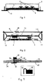
- the surface element according to the invention shown in Fig. 1 shows a plate-shaped component 1 with a sandwich Structure of two thin, film-like cover layers, one Core layer of transverse cell structure, which in particular is honeycomb-shaped, enclose.
- the Clamping device 3 of box-like shape and designed so that the rigidity of component 1 due to its rigidity can withstand and thereby the tension in the component 1 can maintain permanently.
- transducers 2 On the clamping device 3 facing side of the plate-shaped Component 1, three transducers 2 are arranged together form a so-called driver field.
- the converter 2 will controlled with an electrical audio signal and stimulate that plate-shaped component 1 to bending vibrations, whereby it receives the function of a known multimode resonance radiator.
- the supply of the electrical audio signal to the transducers 2 is not shown.
- Set the transducers 2 shown Inertial vibration transducers that vibrate freely without Attachment to another part of the surface element on the plate-shaped component 1 are arranged and the electrical Convert audio signal into mechanical movements and thus that Excite plate-shaped component 1 to bending vibrations.
- the surface element with a through Clamping device 3 held plate-shaped component 1 there is improved acoustics, especially in the bass range.
- this can be designed as a flat speaker Surface element by means of the clamping device 3, the is designed as a rigid body, in the ceiling as a replacement for a passive surface element can be arranged.
- a cover 9 on the underside of the plate-shaped Part 1 of the surface element it is possible to change the look of the surface element according to the invention to the optics of others adapt passive surface elements so that a uniform optical impression of the ceiling by the inventive surface element sound-proofed room is given.
- a surface element is described, which is also a Arrangement from a plate-shaped component 1 and fastened thereon Transducers 2 shows. There are two different ones Transducer 2 arranged on the plate-shaped component 1.
- the Clamping device 3 shows a strut 4, which is a central Strut 12 as an abutment and two struts 13 as a lever and a strut 4a, which has a spring element 8 for Definition of the counteracting force of component 1 Strength, shows.
- the component 1 is in its edge area via a connecting element 11, which is formed like a film, with non-positively the strut 13 connected.
- the strut 13 forms a lever that around a support point formed by the end of the strut 12 is rotatably mounted. If the strut 13, the one forms two-sided lever, one side of which by means of the connecting element 11 connected to the plate-shaped component 1 is pivoted about the pivot point, the tension in the plate-shaped component 1 increased or decreased.
- the other Side of the two-sided lever formed by the strut 13 is, by the strut 4a with the spring element 8 in Direction to the corresponding side of the other two-sided Lever a, which is formed by the other strut 13, moves, thus the distance between these two sides of the struts 13 is reduced, this increases the distance between the other two sides of the two struts 13, so that the plate-shaped component over the Connecting elements 11 is stretched and thus the tension in the plate-shaped component is increased.
- the spring element 8 in particular its spring constant, can be the measure of the tension that is present in the plate-shaped component 1 set in the state of equilibrium and thus also the acoustic properties of the surface element according to the invention establish.
- This formation of the clamping device 3 by means of the struts 13 designed as a two-sided lever shows one technically simple and aesthetically very appealing and technically easy to understand construction of the surface element, which encourages a not inconsiderable proportion of buyers to buy.
- a surface element is particularly suitable as a free-floating element Area element viewed from several sides can be used, especially in high rooms can be used.
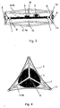
- the surface element shown in FIG. 3 shows in component 1, that with a piezo driver 2 and an electrodynamic dipole driver 2 is equipped.
- the tensioning device 3 shows a Buttress 4, which on both sides of the plate-shaped component 1 is formed.
- the strut 4 shows struts 4a that over rigid node connections form 15 connecting triangles and are interconnected.
- joints 14 are arranged in the edge area of the buttress 4 joints 14 are arranged. Struts are arranged on these joints, which are each provided with spring elements 8 and which the two sides of the strut 4 on both sides of the Try to push apart plate-shaped component 1.
- the Joints 14 are connected in pairs to one another via a tension cable 5. If the joints 14 connected in pairs are moved apart, this leads to a reduction in the lateral deflection of the tension cable 5 transversely to the connecting direction of the two connected joints 14.
- the tension cable 5 is with a tension element 7 connected that the edge region of the plate-shaped component 1 forms, depending on the lengthening or shortening of the side Distance of the rope 5, the plate-shaped component 1 less or more tension.
- the tensioning element 7 shows Holes into which the tension cable 5 engages, which means that through the Extension of the distance between the joints 14 train by the tension rope 5 on the tension element 7 on the bending vibration excited component 1 is transmitted.
- the clamping element 7 is sandwiched with both top layers of the plate-shaped component connected, creating a uniform Initiation of the tensile force of the tension cable 5 is possible and the Risk of tearing out of the connection area 10 due to the reduced transmission force due to the increased number the connection areas is significantly reduced.
- the surface element described is preferably located centrally on one the middle node 15, which the struts 4a of the buttress rigidly connected to each other suspended from the ceiling.
- the struts 4a which on the side facing away from the transducers 2 plate-shaped component 1 are arranged, are partially transparent material and part other than Luminous body formed, whereby the surface element shown acts both as a flat speaker and as a lamp.
- the Energy supply for both those trained as luminous bodies Struts 4a as well as for the converter 2 are made via a common one Supply.
- the electrical acoustic signal is switched on a separation stage from the power supply to the filament separated and fed to the transducers 2.
- the invention shown in a plan view in Fig. 4 Surface element shows a symmetrical three-leg structure of the strut 4 with three struts 4a, the tensioning device 3 form.
- the struts 4a show in their end regions rigid nodes 15, which are firmly connected to each other and to create other elements of the surface element.
- a clamping element 7 is fastened to the ends of the struts 4a, which is tensioned by means of a tension cable 5.
- the clamping element 7 encloses the area of the plate-shaped component 1, which by means of the transducer 2 to bending vibrations and thus too a multi-mode resonance is excited.
- the central node 15 of the three struts 4a is particularly suitable for arranging a suspension point for this surface element, that as a free-hanging surface element with speaker function and more appealing, lighter outer shape is provided.
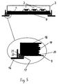
- a plate-shaped component 1 (sound plate) provided on the Bottom has a cover 9 (for example, decorative layer).
- Transducers 2 are applied to the plate-shaped component 1, to set the plate-shaped component 1 in vibration.
- the tensioning device 3 is again provided, which are above the plate-shaped component 1 and the driver 2 is located on the opposite side of the cover Side of the plate-shaped component 1 is attached.
- the plate-shaped component 1 is located in a mounting frame 16, the edge lengths of the plate-shaped component 1 adapted to the predetermined grid dimension of the mounting frame 16 are (maximum format).
- the mounting frame 17 can For example, the entire arrangement can be used to attach a ceiling.
- the plate-shaped component 1 consists of an upper one Cover layer 18, a lower cover layer 20 and an intermediate layer Core layer 19. The three layers are included glued together. With the plate-shaped component 1 is the all-round soft-elastic bead 17 by means of an adhesive joint 21 glued. In the same way, the circumferential soft elastic Bead 17 with the mounting frame 16 by means of an adhesive joint 22 are glued. Cover 9 (decorative layer) covered the lower cover layer 20 completely.
- connection technology is that with the simplest means a simple production and a simple Assembly is given.
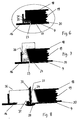
- the embodiment 6 is compared to the embodiment 5 modified so that the plate-shaped Component 1 with a recessed, all-round soft elastic Bead 23 supported on the T-profile of the mounting frame 16 is.
- the circumferential soft elastic bead 17 is in turn by means of Adhesive joints 21 and 22 with the plate-shaped component 1 or the mounting frame 16 glued.
- the plate-shaped component 1 is over the flange width of the Mounting frame 16 milled so that the decorative layer 9 to lie on the same level as the lower edge of the mounting frame 16 is coming. Both the cover 9 and the lower cover layer 20 are in the edge region of the plate-shaped component 1 been removed. In addition, the core layer 19 was made by milling weakened. To compensate for the mechanical weakening the exposed cell structure of the core layer 19 in the edge region can be filled by pouring or filling. Between the mounting frame 16 and the unprocessed area of the plate-shaped component 1 becomes a narrow space 23 kept clear so that the plate-shaped component vibrates does not touch the hard mounting frame 16. Advantage is in addition to a simple assembly that the cover 9 and the Mounting frame 16 lie in one plane.
- the plate-shaped component 1 obliquely chamfered so that a suitably shaped, circumferential bead 24 represents an inclined fit for the plate-shaped component 1.
- the bead 24 is dimensioned so that the cover 9 on the same level as the lower edge of the mounting frame 16 comes to rest.
- the circumferential bead 24 is made of soft elastic Made of plastic and with the plate-shaped Component 1 glued by means of an adhesive joint 25.
- a Snap fastener 26 is provided, which thereby realized constructively is that a circumferential knob-like edition of the Mounting frame 16 with a matching circumferential notch of the bead 24 cooperates.
- a narrow space 23 remains free to touch plate-shaped component 1 and mounting frame 16 when vibrating to prevent or cover 9 can be pulled through so that it also covers the bead 16.
- Fig. 8 is again a self-supporting plate-shaped component 1 consisting of the upper cover layer 18, the core layer 19 and the lower cover layer 20 provided.
- the three layers are in turn with each other glued.
- the edge lengths of the plate-shaped component 1 are, however, smaller than the specified grid dimension of the mounting frame 16 (standard format). That means the plate-shaped Component 1 is produced in a standard format and in a section of a larger, passive one to be made on site plate-shaped component 26 is used.
- the edge of the plate-shaped component 1 is obliquely all around chamfered so that a suitably shaped, all-round elastic Bead 27 for the plate-shaped component 1 an inclined fit represents.
- the bead 27 is dimensioned so that the cover 9 is on the same level as the lower edge of the Mounting frame 16 comes to rest.
- the bead 27 is made of soft elastic Made of plastic and with the plate-shaped Component 1 glued. It serves as a distortion-free, articulated connection with an all-round hard panel frame 28.
- the cover 9 is larger than the lower cover layer 20 of the plate-shaped Component 1, so that an adhesive joint 29 between plate-shaped Component 1 and bead 27 is covered.
- the bead 27 is used in the manufacture of a plate Component 1 glued to this and the panel frame 28.
- the advantage here is that the cover 9 and the mounting frame 16 lie in one level and easy assembly and an airtight fit is guaranteed. For example regardless of the size of the ceiling panels required for insulation a mass produced sound panel in Standard format used.
- a plate-shaped Component 33 integrated in an absorber plate 34.
- a T-frame profile 35 is provided on which on a Side of the absorber plate 34 and on the other side elastic bead 32 connects.
- the bead 32 is there between the plate-shaped component 33 and the T-frame profile 35 arranged.
- the T-frame profile 35 has a snap mechanism 36 on, which clamps the absorber plate 34 and thus the T-frame profile 35 attached to the absorber plate 34.
- the plate-shaped component 33 is attached by means of an adhesive layer 37 the bead 32 attached.
- the attachment of the T-frame profile 35 finally takes place on the elastic bead 32 by means of a Cutting / clamping device 38, the one hand flat on the Bead 32 presses and on the other hand at the corresponding T-protuende for example by means of the cutting / clamping device in a U-profile 38 arranged prongs is held.
- the U profile is put on the T-profile end.
- the bead 32 contains a stiffening body 39 which, for example from a hardened foam layer or deposits consists of and soft elastic material of the bead 32 is surrounded.
- there is one on the front Decorative layer 40 is provided, which over bead 32 and plate-shaped Component 33 extends.
- the bead 32 serves two purposes. On the one hand, it serves for vibration decoupling between plate-shaped component 33, T-frame profile 35 and cutting / clamping device 38. On the other he carries the plate-shaped component 33.
- the in the soft elastic Material of the bead 32 is stiffening in the form of the stiffening body 39 prevents the plate-shaped Component 33 sags or the bead 32 kinks.
- the thickness and the material and thus the necessary stiffness of the bead 32 are among others of the hardness of the soft elastic and depending on the rigid material.
Landscapes
- Engineering & Computer Science (AREA)
- Physics & Mathematics (AREA)
- Acoustics & Sound (AREA)
- Signal Processing (AREA)
- Multimedia (AREA)
- Diaphragms For Electromechanical Transducers (AREA)
- Details Of Audible-Bandwidth Transducers (AREA)
Abstract
Description
Die Erfindung betrifft ein Flächenelement mit einem plattenförmigen Bauteil und mit wenigstens einem Wandler, der das Bauteil zu Biegeschwingungen anregt, es in Resonanz treten lässt und dadurch einen akustischen Multimoden-Resonanz-Strahler bildet. Dieses Flächenelement hat die Funktion eines Flachlautsprechers.The invention relates to a surface element with a plate-shaped Component and with at least one converter that the component stimulates bending vibrations, resonates and thereby forming an acoustic multimode resonance radiator. This surface element has the function of a flat speaker.
Es sind Lautsprecher bekannt, die als Lautsprecherbox an der Decke befestigt sind und die elektroakkustische Wandler mit einer durch eine Schwingspule getriebenen Membran zur Erzeugung der Schallwellen in einem Gehäuse aufweisen. Diese Flachlautsprecher erweisen sich als sehr schwer, sehr teuer und im Hinblick auf die Gestaltung des Raumes als sehr ungeeignet.Loudspeakers are known which are used as loudspeakers on the Are attached to the ceiling and the electroacoustic transducer with a through a voice coil driven membrane for generation of sound waves in a housing. These flat speakers turn out to be very heavy, very expensive and in view on the design of the room as very unsuitable.
Weiterhin sind Lautsprecher bekannt, die eine Vielzahl von einzelnen elektroakustischen Wandlern in der Decke aufweisen, wobei die elektroakustischen Wandler weitgehend gleichmäßig über die gesamte Decke verteilt sind. Die elektroakustischen Wandler zeigen einen typischen Aufbau mit einer durch eine Schwingspule getriebene Membran, die die Schallwellen durch Hubbewegungen erzeugen. Die Vielzahl an elektroakustischen Wandlern erfordert eine sehr aufwendige Verkabelung in der Decke, was im Zusammenhang mit der Vielzahl an elektroakustischen Wandlern zu einer sehr teuren Anordnung zur Beschallung eines Raumes führt. Diese Vielzahl an elektroakustischen Wandlern ist erforderlich, da diese elektroakustischen Wandler eine sehr ausgeprägte Richtungscharakteristik aufweisen und bei einem Zusammenwirken von wenigen elektroakustischen Wandlern keine ausreichende Schallversorgung im gesamten Raum gegeben ist. Furthermore, loudspeakers are known that have a large number of individual ones have electroacoustic transducers in the ceiling, wherein the electroacoustic transducers largely evenly over the entire ceiling are spread out. The electroacoustic transducers show a typical structure with a through a voice coil driven membrane, which the sound waves through stroke movements produce. The variety of electroacoustic transducers required a very elaborate wiring in the ceiling, which is related with the multitude of electro-acoustic transducers into one very expensive arrangement leads to the sound of a room. This A large number of electroacoustic transducers is required because these electro-acoustic transducers have a very pronounced directional characteristic have and with a cooperation of few electroacoustic transducers do not have sufficient sound supply is given in the entire room.
Weiterhin sind aus der WO 97/09843 Deckenplatten mit einem Wandler bekannt, der die Deckenplatte in Biegeschwingungen versetzen kann und diese so in Resonanz treten lässt, dass diese Platte einen Multimoden-Resonanz-Strahler zur Wiedergabe eines zugeführten elektrischen Audiosignal bildet. Diese Deckenplatte zeigt eine sehr gute räumliche Abstrahlcharakteristik des akustischen Audiosignals. Sie zeigt aber eine unbefriedigende Akustik insbesondere im Bassbereich und sie zeigt durch die plane Ausbildung als Deckenplatte nur eine begrenzte Zugänglichkeit für einen designerischen Spielraum bei der Gestaltung der Deckenplatte mit dem Wandler.Furthermore, from WO 97/09843 ceiling tiles with a Known transducer that put the ceiling panel in bending vibrations can and resonate so that this Plate a multi-mode resonance emitter to play a supplied electrical audio signal forms. This ceiling tile shows a very good spatial radiation characteristic of the acoustic Audio signal. However, it shows unsatisfactory acoustics especially in the bass range and it shows through the plane Training as a ceiling tile has limited access for design freedom when designing the ceiling tile with the converter.
Der Erfindung liegt die Aufgabe zugrunde, ein Flächenelement zu schaffen, welches gute akustische Eigenschaften insbesondere im Bassbereich und auch im Hinblick auf die räumliche Schallverteilung zeigt und das darüber hinaus eine preisgünstige Möglichkeit zur Beschallung eines Raumes ermöglicht und darüber hinaus designerischen Variationen zugänglich ist.The invention has for its object to a surface element create what good acoustic properties especially in the Bass range and also with regard to the spatial sound distribution shows and that is also an inexpensive option for sound reinforcement in a room and above design variations are also accessible.
Diese Aufgabe wird erfindungsgemäß durch ein Flächenelement mit
den in Anspruch 1 angegebenen Merkmalen gelöst.This object is achieved by a surface element
solved the features specified in
Vorteilhafte Weiterbildungen ergeben sich aus den Unteransprüchen.Advantageous further developments result from the subclaims.
Das erfindungsgemäße Flächenelement zeigt ein plattenförmiges Bauteil, auf dem wenigstens ein Wandler angeordnet ist, welchem ein elektrisches Audiosignal zugeführt wird und welcher das plattenförmige Bauteil in Biegeschwingungen versetzt, die das Bauteil in Resonanz treten lassen und es zu einem Multimoden-Resonanz-Strahler werden lassen. Das Flächenelement zeigt eine Spannvorrichtung, welche mit dem plattenförmigen Bauteil verbunden ist und welche dieses plattenförmige Bauteil unter Spannung hält. Durch den gespannten Zustand des plattenförmigen Bauteils verändern sich die akustischen Eigenschaften des Flächenelementes, welches als Flachlautsprecher wirkt, dahingehend, dass es im Vergleich zu einem frei gelagerten Bauteil zusätzliche Resonanzen im Tieftonbereich bildet. Damit lassen sich bessere akustische Eigenschaften im Tieftonbereich bei sehr guter räumlicher Verteilung des Schalls erreichen. Damit erweist sich dieses Flächenelement als besonders geeignet für den Einsatz als Flachlautsprecher insbesondere in großen Räumen. Gerade bei einem Einsatz in niedrigen, großflächigen Räumen kommen die vorteilhaften akustischen Eigenschaften besonders zur Geltung. Weiterhin erweist sich dieses Flächenelement als sehr kostengünstig, da zur ausreichenden Beschallung von ansprechender Qualität nur eine geringe Anzahl von erfindungsgemäßen Flächenelementen notwendig ist und dadurch die Kosten für eine Beschallungsanlage für einen vorgegebenen Raum sehr niedrig gehalten werden können.The surface element according to the invention shows a plate-shaped Component on which at least one converter is arranged, which an electrical audio signal is supplied and which the plate-shaped component in bending vibrations that the Let the component resonate and it becomes a multimode resonance radiator let be. The surface element shows one Clamping device, which is connected to the plate-shaped component and which is this plate-shaped component under tension holds. Due to the tensioned condition of the plate-shaped Component, the acoustic properties of the surface element change, which acts as a flat speaker in that that it is compared to a freely stored component creates additional resonances in the low frequency range. Leave with it better acoustic properties in the bass range achieve a very good spatial distribution of the sound. In order to this surface element proves to be particularly suitable for use as a flat speaker, especially in large rooms. Especially when used in low, large rooms advantageous acoustic properties come in particular to advantage. This surface element also proves to be as very inexpensive because of sufficient sound of appealing quality only a small number of the invention Area elements is necessary and therefore the Cost of a sound system for a given room can be kept very low.
Dabei ist die Spannvorrichtung so ausgebildet, dass sie das plattenförmige Bauteil umgreift und das plattenförmige Bauteil in Richtung der flächigen Ausdehnungsrichtung spannt bzw. gespannt hält. Diese Spannvorrichtung kann als vollflächiger Kasten das plattenförmige Bauteil umfassen und in einem Bereich eine Ausnehmung aufweisen, die die Schallabstrahlung des plattenförmigen Bauteils ermöglicht. Dabei ist der Randbereich des plattenförmigen Bauteils fest mit der Spannvorrichtung verbunden, so dass die durch das gespannte plattenförmige Bauteil gegebenen Spannkräfte auf die Spannvorrichtung übertragen werden und das plattenförmige Bauteil in einer festgelegten, definierten Lage bzw. in einem entsprechenden gespannten Zustand gehalten werden kann. Weiterhin ist es möglich, dass die kastenförmige Spannvorrichtung Ausnehmungen zeigt und dadurch die Möglichkeit gibt, Schall auch durch die weiteren Öffnungen abzugeben. Dabei ist es auch möglich, dass die Spannvorrichtung nur aus einzelnen Stegen oder Streben gebildet wird, die der Spannung im plattenförmigen Bauteil entgegenwirken und diese Spannung aufrechterhalten. The tensioning device is designed so that it engages plate-shaped component and the plate-shaped component tensioned or stretched in the direction of the planar direction of expansion holds. This clamping device can be used as a full-surface box comprise the plate-shaped component and in one area have a recess that the sound radiation of the plate-shaped Component. The edge area of the plate-shaped component firmly connected to the clamping device, so that given by the tensioned plate-shaped component Clamping forces are transferred to the clamping device and the plate-shaped component in a defined, defined Position or kept in a corresponding tensioned state can be. It is also possible that the box-shaped Clamping device shows recesses and thereby the possibility gives sound through the other openings. It is also possible that the clamping device is formed only from individual webs or struts that the Counteract tension in the plate-shaped component and this Maintain tension.
Nach einer bevorzugten Ausbildungsform der Erfindung wird die Spannvorrichtung dazu verwendet, das Flächenelement an der Decke, beispielsweise an einem Haken beispielsweise in der Decke zu befestigen oder das Flächenelement mit der Spannvorrichtung in eine Ausnehmung in der Decke einzubringen. Anstelle einer Decke ist jedoch auch jede andere Fläche geeignet. In diesem Fall wird das Flächenelement in der Decke an der Spannvorrichtung gehalten und nicht an dem plattenförmigen Bauteil, wodurch die besonderen akustischen Eigenschaften des plattenförmigen Bauteils unverändert erhalten bleiben. Damit besteht kein Einfluss zwischen der Position und der Art der Aufhängung an oder in der Decke und den akustischen Eigenschaften des Flächenelementes. Dabei ist die Größe und die Gestalt des Flächenelementes vorzugsweise so gewählt, dass es ein passives Deckenpaneel ohne schallabgebende Funktion ersetzen kann, ohne dass eine geänderte Aufhängung und geänderte optische Eigenschaften der Decke mit dem erfindungsgemäßen Flächenelement als Ersatz für ein passives Deckenpaneel gegeben sind.According to a preferred embodiment of the invention, the Clamping device used the surface element on the ceiling, for example on a hook, for example in the ceiling to fix or the surface element with the clamping device in a recess in the ceiling. Instead of one However, any other surface is also suitable for the ceiling. In this Fall the surface element in the ceiling on the jig held and not on the plate-shaped component, whereby the special acoustic properties of the plate-shaped Component remain unchanged. So there is no influence between the position and the type of suspension at or in the ceiling and the acoustic properties of the surface element. The size and shape of the surface element preferably chosen so that it is a passive ceiling panel can replace without sound-emitting function, without a changed Suspension and changed optical properties of the ceiling with the surface element according to the invention as a replacement for a passive ceiling panel are given.
Es hat sich besonders bewährt, die Spannvorrichtung durch ein Strebewerk zu realisieren, das die Spannkräfte des Bauteils aufnimmt und das Bauteil unter Spannung hält. Das Strebewerk, das das plattenförmige Bauteil, welches die akustischen Signale durch Mulitmoden-Resonanz erzeugt, umgreift, ermöglicht bei ausreichender Widerstandsfähigkeit gegen die Spannkräfte des gespannten plattenförmigen Bauteils eine sehr gewichtsreduzierte Ausbildung der Spannvorrichtung, weshalb diese Ausbildung des Flächenelementes besonders geeignet für die Anordnung in einer Decke oder an einer Decke ist. Durch diese Ausbildung des Flächenelementes ist es möglich, auf aufwendige, kostenintensive Befestigungselemente in der Decke oder an der Decke zur Befestigung des Flächenelementes zu verzichten, was neben den Kostenvorteilen auch Vorteile für die äußere Gestaltung des Flächenelementes und der Decke mit dem Flächenelement gibt. Dabei hat sich die Verwendung von Leichtmetallen und die Verwendung von Hohlkörpern, insbesondere von Röhren zur Bildung der Streben für das Strebewerk zur weiteren Reduktion des Gewichtes bei ausreichender Widerstandkraft gegen die Spannkraft des plattenförmigen Bauteils besonders bewährt.It has proven particularly useful to use a jig To realize the buttress, the clamping forces of the component records and keeps the component under tension. The buttress, which is the plate-shaped component, which the acoustic signals generated by multi-mode resonance, embraces, enables at sufficient resistance to the resilience of the tensioned plate-shaped component a very reduced weight Training of the clamping device, which is why this training of the surface element particularly suitable for the arrangement in a blanket or on a blanket. Through this Formation of the surface element, it is possible to costly fasteners in the ceiling or on the To waive ceiling for fastening the surface element, what in addition to the cost advantages, there are also advantages for the external design of the surface element and the ceiling with the surface element gives. The use of light metals and the Use of hollow bodies, especially tubes for formation the struts for the strut to further reduce weight with sufficient resistance to the resilience of the plate-shaped component has proven particularly successful.
Wird das Strebewerk so ausgebildet, dass dessen Streben nur unter Zug oder Druck belastet sind und das Strebewerk eine polygone Gestalt zeigt, so ist nicht nur eine sehr sichere Struktur des Strebewerks gegeben, das sich durch eine besonders leichte Konstruktion auszeichnet und darüber hinaus eine sehr ästhetische Gestalt aufweist. Hierdurch ergeben sich besondere designerische Möglichkeiten für die Verwendung und Ausbildung des Flächenelementes, da nun das Flächenelement mit Spannvorrichtung aus einem Strebewerk als Gesamtes ohne ästhetische Beeinträchtigungen sichtbar gemacht werden kann. Diese gesamte Anordnung erweist sich als besonders geeignet in Räumen mit sehr hohen Decken, wo dieses erfindungsgemäße Flächenelement an der Decke, insbesondere hängend, befestigt wird und dadurch von verschiedenen Seiten eingesehen werden kann. Hier tritt die besondere ästhetische Gestaltung des Strebewerkes in Verbindung mit der plattenförmigen Gestalt des Bauteils in den Vordergrund, was den Gegenstand der Erfindung einen künstlerischen Rang verleiht.Is the strut designed so that its struts are only under Train or pressure are loaded and the buttress is a polygon Shaping is not just a very secure structure of the buttress, which is characterized by a particularly light weight Construction distinguishes and also a very aesthetic Has shape. This results in special design Possibilities for using and training the Surface element, because now the surface element with clamping device from a crosspiece as a whole without aesthetic impairments can be made visible. This entire arrangement proves to be particularly suitable in rooms with very high ceilings, where this surface element according to the invention on the Ceiling, especially hanging, is attached and thereby by different pages can be viewed. Here comes the special aesthetic design of the buttress in conjunction with the plate-like shape of the component in the foreground, what the subject of the invention an artistic Gives rank.
Durch die Ausbildung des Strebewerkes mit Streben, die nur auf Druck oder unter Zug belastet sind und nicht auf Biegung beansprucht sind, gelingt es eine sehr einfache und dauerhafte und gewichtsarme Konstruktion der Spannvorrichtung zu schaffen, die durch ihr geringes Gewicht besonders für den Einsatz in einem Flächenelement geeignet ist.By training the strut with struts that are only on Are under pressure or under tension and are not subjected to bending are very simple and lasting and to create a low-weight construction of the clamping device, due to its low weight, it is particularly suitable for use in one Surface element is suitable.
Nach einer bevorzugten Ausführungform der Erfindung werden die Spannkräfte zwischen dem Bauteil und dem Strebewerk über ein Spannseil übertragen, das zwischen dem Strebewerk und dem gespannten plattenförmigen Bauteil angeordnet ist und so unter Zug steht, dass die Spannung des plattenförmigen Bauteils erhalten bleibt. Dabei hat sich besonders bewährt, das Spannseil im Randbereich des plattenförmigen Bauteils entweder in Löcher eingreifen zu lassen oder es in Hohlsaumabschnitten im Randbereich des Bauteils zu führen und nach außen zu dem Strebewerk abzuspannen. Durch diese Ausbildungen ist eine Spannvorrichtung gegeben, die in ihrem Spannmaß den jeweiligen Bedürfnissen sehr einfach anzupassen ist und dabei eine gleichmäßige Spannung über das gesamte Spannseil auf das plattenförmige Bauteil überträgt. Darüber hinaus erweist sich diese Ausbildung mit dem Spannseil als sehr einfach zu fertigen, da die Bestandteile der Spannvorrichtung in ihrer Fertigungstoleranz sehr wenig kritisch sind und dadurch ein Flächenelement von hoher Fertigungsqualität gegeben ist. Dies führt zu einem sehr kostengünstigen Flachlautsprecher.According to a preferred embodiment of the invention, the Clamping forces between the component and the strut over one Transfer tension rope that between the buttress and the tensioned plate-shaped component is arranged and so under Train stands that the tension of the plate-shaped component is maintained remains. The tension rope has proven particularly useful either in holes in the edge area of the plate-shaped component to intervene or in hemstitch sections in the edge area of the component and outwards to the strut to tension. Through this training is a clamping device given that in their tension measure the respective needs very much is easy to adjust while maintaining an even tension over transfers the entire tension cable to the plate-shaped component. In addition, this training proves itself with the Tension rope as very easy to manufacture because the components of the Clamping device very little critical in its manufacturing tolerance are and therefore a surface element of high manufacturing quality given is. This leads to a very inexpensive Flat speakers.
Es hat sich besonders bewährt, das plattenförmige Bauteil, welches durch ein Spannseil gespannt gehalten wird, in seinem Randbereich, in welchem das Spannseil angeordnet ist, durch ein Spannelement zu bilden, das die Kräfte von dem Spannseil gleichmäßig auf den Bereich des plattenförmigen Bauteils überträgt, der zur Multimoden-Resonanz-Bildung besonders geeignet ist und dazu angeregt wird. Dabei ist das Spannelement mit den Löchern bzw. mit den Hohlraumabschnitten zur Aufnahme des Spannseils versehen und es umschließt den gesamten Bereich des plattenförmigen Bauteils, welcher zur Bildung von Multimoden-Resonanzen besonders geeignet und vorgesehen ist. Dieser Bereich des plattenförmigen Bauteils ist bevorzugt als ebene Platte ausgebildet, die sandwichartig aus mindestens drei übereinander angeordneten, vollflächig verklebten oder verschweißten Schichten aufgebaut. Dabei sind die Deckschichten so ausgebildet, dass die Quadratwurzel aus dem Quotienten ihres Elasttzitätsmoduls zu deren Dichte besonders hoch insbesondere > 3000 m/s ist. Hierzu eignen sich insbesondere faserverstärkte Kunststofffolien oder dünne Metallfolien. Die Kernschicht ist bevorzugt als geschäumter Kern oder als wabenförmig ausgebildete Kernschicht ausgebildet, welche vorzugsweise eine Dichte von unter 50 kg/m3 aufweisen. Vorzugsweise ist das Spannelement entweder einseitig an einer der Deckschichten befestigt und überträgt somit die Spannkraft zwischen der Spannvorrichtung und der sandwichförmigen Struktur des plattenförmigen Bauteils über das Spannelement auf diese eine Deckschicht oder das Spannelement ist zugleich mit der oberen Deckschicht als auch mit der unteren Deckschicht verbunden, was eine gleichmäßige und verringerte Kraftübertragung auf die einzelnen Deckschichten bewirkt. Mithin lassen sich durch diese zweiseitige Verbindung des Spannelementes mit beiden Deckschichten größere Spannkräfte zur Spannvorrichtung übertragen und damit einen größeren Bassbereich für zusätzliche Multimoden-Resonanzen des Flächenelementes erschließen.It has proven particularly useful to form the plate-shaped component, which is held tensioned by a tensioning rope, in its edge region in which the tensioning rope is arranged by a tensioning element which transmits the forces from the tensioning rope evenly to the area of the plate-shaped component, which is particularly suitable for multimode resonance formation and is stimulated to do so. The tensioning element is provided with the holes or with the cavity sections for receiving the tensioning cable and it encloses the entire area of the plate-shaped component, which is particularly suitable and provided for the formation of multimode resonances. This area of the plate-shaped component is preferably designed as a flat plate, which is constructed in a sandwich-like manner from at least three layers that are arranged one above the other, fully glued or welded. The cover layers are designed so that the square root of the quotient of their modulus of elasticity to their density is particularly high, in particular> 3000 m / s. Fiber-reinforced plastic films or thin metal films are particularly suitable for this. The core layer is preferably designed as a foamed core or as a honeycomb-shaped core layer, which preferably have a density of less than 50 kg / m 3 . Preferably, the tensioning element is either fastened on one side to one of the cover layers and thus transmits the tensioning force between the tensioning device and the sandwich-like structure of the plate-shaped component via the tensioning element to this cover layer or the tensioning element is simultaneously connected to the upper cover layer and to the lower cover layer which causes a uniform and reduced power transmission to the individual cover layers. This double-sided connection of the tensioning element to both cover layers means that greater tensioning forces can be transmitted to the tensioning device, thus opening up a larger bass range for additional multimode resonances of the surface element.
Erstreckt sich die Spannvorrichtung zu beiden Seiten des plattenförmigen Bauteils, so ist zum einen eine sehr stabile und auch hohen Spannkräften des plattenförmigen Bauteils widerstehende Spannvorrichtung für das Flächenelement als Flachlautsprecher gegeben. Hierdurch kann eine Erweiterung der Anzahl der Multimoden-Resonanzen im Tieftonbereich, die auch "Trommelresonanzen" genannt werden, durch die erhöhte Spannung des plattenförmigen Bauteils erreicht werden. Dies führt zu einem akustisch sehr ansprechenden Klangverhalten, das aufgrund der guten Basswidergabe für den Einsatz als Flachlautsprecher besonders geeignet ist. Darüber hinaus erweist sich das Flächenelement mit einer beidseitigen Spannvorrichtung, die insbesondere mit einem Strebewerk versehen ist, als ästhetisch sehr ansprechend, was insbesondere bei einer Ausbildung als von der Decke herunterhängendes Flächenelement gegeben ist.The tensioning device extends to both sides of the plate-shaped Component, on the one hand is a very stable and also withstand high clamping forces of the plate-shaped component Clamping device for the flat element as a flat speaker given. This can increase the number the multimode resonances in the low frequency range, which are also called "drum resonances" be called by the increased tension of the plate-shaped component can be achieved. This leads to one acoustically very appealing sound behavior, due to the good bass reproduction especially for use as a flat speaker suitable is. In addition, the surface element proves to be with a double-sided clamping device, which in particular is provided with a buttress, as aesthetically very appealing, which is particularly important when training as from Ceiling hanging surface element is given.
Als besonders bevorzugte Ausbildung der Erfindung hat sich gezeigt, die Spannvorrichtung mit wenigstens einem Federelement zu versehen, das entweder als Zugfeder oder als Druckfeder wirkt und durch seine Federkraft der Spannkraft des gespannten plattenförmigen Bauteils entgegenwirkt. Dabei entsteht ein Kräftegleichgewicht zwischen der Spannung in dem plattenförmigen Bauteil und der Federkraft des Federelementes in der Spannvorrichtung. Dabei ist die Spannvorrichtung so ausgebildet, dass die Federkraft des Federelementes über die beweglich ausgebildete Spannvorrichtung auf das plattenförmige Bauteil übertragen werden kann. Diese Spannvorrichtung zeigt gelenkige Verbindungen der einzelnen Bestandteile der Spannvorrichtung, wodurch die erforderliche Beweglichkeit der Spannvorrichtung zur Übertragung der Federkraft des Federelementes auf das gespannte Bauteil ermöglicht ist. Vorzugsweise ist das Federelement entweder austauschbar, also gegen ein Federelement mit einer anderen Federkonstante ersetzbar, oder das Federelement ist durch ein Stellelement in seiner Federwirkung und somit in seiner Federkonstante veränderlich ausgebildet. Hierdurch lassen sich entsprechend dem jeweils geeigneten Anbringungsort des Flächenelementes die jeweils optimalen akustischen Eigenschaften abhängig von der Federeigenschaft des Federelementes und damit dem Maß der Spannung in dem plattenförmigen Bauteil festlegen. Dabei besteht auch die Möglichkeit, das Flächenelement für bestimmte akustische Signale entsprechend in dem akustischen Klangverhalten anzupassen, das heißt stark bassbetonte akustische Signale werden mit einem Flächenelement mit durch das Federelement stärker gespannten Bauteil wiedergegeben, während akustische Signale mit geringem oder keinem relevanten Bassanteil mit nahezu ungespanntem plattenförmigen Bauteil wiedergegeben werden.A particularly preferred embodiment of the invention has been shown the tensioning device with at least one spring element to be provided either as a tension spring or as a compression spring acts and by its spring force the resilience of the tensioned counteracts plate-shaped component. This creates a Force balance between the tension in the plate-shaped Component and the spring force of the spring element in the clamping device. The tensioning device is designed so that the spring force of the spring element over the movably designed Transfer the clamping device to the plate-shaped component can be. This jig shows articulated connections of the individual components of the clamping device, whereby the required mobility of the clamping device Transfer of the spring force of the spring element to the tensioned Component is enabled. Preferably the spring element is either interchangeable, i.e. against one spring element with another Spring constant replaceable, or the spring element is by an adjusting element in its spring action and thus in its spring constant variably trained. This allows according to the appropriate location of the surface element the optimal acoustic properties of the spring properties of the spring element and thus determine the degree of tension in the plate-shaped component. It is also possible to use the surface element for certain acoustic signals accordingly in the acoustic Adapting the sound behavior, that means strong bass-emphasized acoustic Signals are with a surface element with the spring element reproduced more tensioned component while acoustic signals with little or no relevant bass content reproduced with an almost unstressed plate-shaped component become.
Daneben hat es sich als besonders geeignet erwiesen, die für die Wandler erforderlichen elektrischen Zuleitungen durch die Spannvorrichtung selbst oder sie an der Spannvorrichtung angeordnet auszubilden. Dies erweist sich insbesondere bei einer Spannvorrichtung mit einem Strebewerk als besonders geeignet, da durch die Streben des Strebewerks eine sehr sichere Verlegung der elektrischen Zuleitungen gegeben ist, die definierte Positionen einnimmt und dabei nicht beweglich, frei durch den Raum geführt werden, wodurch ein wenig ansprechender optischer Eindruck des Flächenelementes gegeben ist.In addition, it has proven to be particularly suitable for the electrical leads required by the converter Clamping device itself or arranged on the clamping device to train. This is particularly evident in one Clamping device with a strut as particularly suitable, because of the struts of the strut a very safe installation of the electrical supply lines, the defined Assumes positions and is not movable, freely through the Space to be led, making a little more appealing visual Impression of the surface element is given.
Als besonders vorteilhaft hat sich erwiesen eine oder mehrere Streben des Strebewerkes mit einem oder mehreren Leuchtkörpern zu versehen und dadurch ein Flächenelement zu schaffen, das sowohl die Funktionalität eines Flachlautsprechers als auch einer Deckenleuchte in sich vereinigt. Dabei erfolgt dies in einer Weise, dass gerade bei der Ausbildung der Leuchtkörper als länglich erstreckte Leuchtkörper, die gegebenenfalls die Streben des Strebewerks bilden, eine sehr leichte und sehr ansprechende Gestaltung des Flächenelementes gegeben ist. Dieses Design des Flächenelementes erweist sich aufgrund seiner Leichtigkeit und seiner funktionellen Ausbildung als sehr interessant und als sehr ansprechend für den Benutzer.One or more has proven to be particularly advantageous Striving of the strut with one or more lighting elements to provide and thereby create a surface element that both the functionality of a flat speaker as well as one Ceiling lamp united. This is done in one Way that just when training the filament as elongated filament, possibly the struts form the buttress, a very light and very appealing Design of the surface element is given. This The design of the surface element proves to be light and its functional training as very interesting and as very appealing to the user.
Durch die Verwendung von durchsichtigen Materialien für die Streben des Strebewerkes und/oder des plattenförmigen Bauteils wird ein zusätzlicher optischer Effekt durch Lichtbrechungen und Lichtbeugungen und Lichtverfärbungen erreicht, was das Design dieses Flächenelementes noch interessanter macht. Weiterhin ist es möglich, dieses Flächenelement mit mehreren verschiedenfarbigen Leuchtkörpern zu versehen, die entsprechend dem akustischen Signal unterschiedlich angesteuert werden, so dass nicht nur ein nach dem elektrischen Audiosignal gesteuertes akustisches Signal, sondern auch ein dementsprechend gesteuertes optisches Signal durch dieses besondere Flächenelement wiedergegeben wird. Bei dieser besonderen Ausbildung des Flächenelementes als Lichtquelle und als akustische Quelle hat es sich besonders vorteilhaft erwiesen, die Energieversorgung der Leuchtkörper auch zum Betreiben der Wandler zu verwenden. Hierdurch entsteht eine sehr effiziente Anordnung zur Energieversorgung beider Funktionalitäten des Flächenelementes, was die Kosten eines derartigen Flächenelementes insbesondere vor dem Hintergrund, dass eine Mehrzahl derartiger Flächenelemente zur Beschallung und Beleuchtung eines größeren Raumes notwendig sind, niedrig hält.By using transparent materials for the Striving the strut and / or the plate-shaped component becomes an additional optical effect due to light refraction and light diffraction and light discoloration achieved what the design makes this surface element even more interesting. Farther it is possible to use this surface element with several different colors Luminaires to be provided accordingly the acoustic signal can be controlled differently, so that not just one controlled by the electrical audio signal acoustic signal, but also a correspondingly controlled one optical signal through this special surface element is played. In this particular training of the Has surface element as a light source and as an acoustic source it has proven particularly advantageous to supply energy the filament can also be used to operate the converter. This creates a very efficient arrangement for energy supply both functionalities of the surface element what the costs of such a surface element in particular the background that a plurality of such surface elements necessary for sound and lighting of a larger room are low.
Neben der Möglichkeit, die Wandler als Inertialschwingungswandler auszubilden hat es sich gerade bei schweren Wandlern bewährt, diese mit Streben der Spannvorrichtungen zu verbinden und dadurch das Gewicht der Wandler durch die Spannvorrichtung aufzunehmen und von dem plattenförmigen Bauteil fernzuhalten. Hierdurch ist es möglich, dass die plattenförmigen Bauteile auch bei schweren Wandlern frei zu Biegeschwingungen angeregt werden können und dadurch besonders viele und verschiedene Multimoden-Resonanzen in dem plattenförmigen Bauteil entwickeln können. Die Anzahl und die Verteilung dieser Resonanzen steht in unmittelbarem Zusammenhang mit den guten akustischen Eigenschaften des erfindungsgemäßen Flächenelementes. Werden auf dem plattenförmigen Bauteil mehrere Wandler, insbesondere schwere Wandler, angeordnet, so werden diese bevorzugt an den Streben des Strebewerkes befestigt, wodurch die vorbeschriebenen Vorteile in besonderem Maße auch bei mehreren Wandlern erreicht werden können.In addition to the possibility of using the transducer as an inertial vibration transducer it has to train especially with heavy converters proven to connect these with struts of the clamping devices and thereby the weight of the transducers by the jig record and keep away from the plate-shaped component. This makes it possible for the plate-shaped components even with heavy transducers freely excited to bending vibrations and therefore a particularly large number and different multimode resonances develop in the plate-shaped component can. The number and distribution of these resonances is clear in direct connection with the good acoustic properties of the surface element according to the invention. Are on the plate-shaped component several transducers, especially heavy ones Transducers arranged, so they are preferred on the struts of the crossbar attached, which gives the advantages described above especially achieved with several converters can be.
Wird das Flächenelement mit seiner Energieversorgung und Audiosignalzuführung an das Gleichspannungsversorgungsnetz der Beleuchtung angeschlossen, die beispielsweise als 100 V Gleichspannungsnetz ausgebildet ist, so hat es sich bewährt, der 100 V Gleichspannung das Audiosignal zu überlagern und es dann in dem Flächenelement durch eine galvanische Trennstufe abzutrennen und es dem oder den Wandlern zuzuführen. Durch diese Ausbildung, insbesondere bei einem Deckenpaneel mit Leuchtkörpern ist es möglich, die Anzahl der elektrischen Leitungen, die zu dem Flächenelement führen, zu reduzieren, was den Einbau des Flächenelementes in oder an einer Decke wesentlich vereinfacht. Will the surface element with its energy supply and audio signal supply to the DC voltage supply network for the lighting connected, for example as a 100 V DC network trained, it has proven to be the 100th V DC voltage overlay the audio signal and then turn it into to separate the surface element by a galvanic isolator and feed it to the converter (s). Through this training, especially with a ceiling panel with light fixtures it is possible to determine the number of electrical wires that are too lead the surface element to reduce what the installation of the Surface element in or on a ceiling significantly simplified.
Schließlich kann gemäß einer bevorzugten Ausführungsform der Erfindung das plattenförmige Bauteil einen umlaufenden weichelastischen Wulst (Randwulst)aufweisen. Der Wulst kann dabei unter anderem das Bauteil an seinem äußersten Umfang umschließen, in das plattenförmige Bauteil eingelassen werden oder schräg an das plattenförmige Bauteil angefast werden. Bevorzugt wird der Wulst mittels eines Schnappbefestigungsmechanismus oder einer Schneid-/Klemmvorrichtung am Rahmen und/oder plattenförmigen Bauteil befestigt. Bei einer Weiterbildung der Erfindung enthält der Wulst einen Verstärkungskörper.Finally, according to a preferred embodiment, the Invention the plate-shaped component a circumferential soft elastic Show bead (edge bead). The bead can do it among other things enclose the component at its extreme circumference, be embedded in the plate-shaped component or be chamfered at an angle to the plate-shaped component. Prefers is the bead by means of a snap fastening mechanism or a cutting / clamping device on the frame and / or plate-shaped Component attached. In a further development of the invention the bead contains a reinforcing body.
Bevorzugte Ausführungsbeispiele der Erfindung sind in den Zeichnungen dargestellt und werden in Folgendem näher beschrieben.
- Fig. 1
- zeigt in einer geschnittenen Darstellung ein beispielhaftes Flächenelement mit kastenförmiger Spannvorrichtung.
- Fig. 2
- zeigt in geschnittener Darstellung ein beispielhaftes Flächenelement mit einer Spannvorrichtung mit Strebewerk,
- Fig. 3
- zeigt in einer geschnittenen Darstellung ein anderes beispielhaftes Flächenelement mit Spannvorrichtung und Strebewerk,
- Fig. 4
- zeigt in einer Draufsicht ein anderes beispielhaftes Flächenelement mit Spannvorrichtung, mit Strebewerk und Spannelement,
- Fig. 5
- zeigt ein anderes beispielhaftes Deckenelement mit Spannvorrichtung und einem aufgesetzten weichelastischen Randwulst,
- Fig. 6
- zeigt ein beispielhaftes Deckenelement mit einer Spannvorrichtung und einem eingelassenen, weichelastischen Randwulst,
- Fig. 7
- zeigt ein beispielhaftes Deckenelement mit einem schräg angefasten, weichelastischen Randwulst und einer Schnappbefestigung,
- Fig. 8
- zeigt ein beispielhaftes Deckenelement mit einem weichelastischen Randwulst und einer Schnappbefestigung in einem Ausschnitt eines passiven Deckenelements und
- Fig. 9
- zeigt ein beispielhaftes Deckenelement mit einem einen Verteilungskörper enthaltenden, weichelastischen Randwulst und einer Schneid-/Klemmvorrichtung.
- Fig. 1
- shows in a sectional view an exemplary surface element with a box-shaped clamping device.
- Fig. 2
- shows a sectional representation of an exemplary surface element with a clamping device with a strut,
- Fig. 3
- shows in a sectional representation another exemplary surface element with tensioning device and strut,
- Fig. 4
- shows a top view of another exemplary surface element with tensioning device, with strut and tensioning element,
- Fig. 5
- shows another exemplary ceiling element with tensioning device and a soft elastic edge bead,
- Fig. 6
- shows an exemplary ceiling element with a tensioning device and a recessed, soft-elastic edge bead,
- Fig. 7
- shows an exemplary ceiling element with an obliquely chamfered, soft elastic edge bead and a snap fastening,
- Fig. 8
- shows an exemplary ceiling element with a soft elastic edge bead and a snap fastening in a section of a passive ceiling element and
- Fig. 9
- shows an exemplary ceiling element with a soft elastic edge bead containing a distribution body and a cutting / clamping device.
Das in Fig. 1 dargestellte erfindungsgemäße Flächenelement
zeigt ein plattenförmiges Bauteil 1 mit einem sandwichartigen
Aufbau aus zwei dünnen folienartigen Deckschichten, die eine
Kernschicht von transversaler Zellstruktur, die insbesondere
wabenförmig ausgebildet ist, umschließen. Im Randbereich des
plattenförmigen Bauteils ist ein Verbindungsbereich 10 zu der
Spannvorrichtung 3 gegeben, die das Bauteil 1 umgreift und das
vorgespannte Bauteil 1 unter Spannung hält. Dabei ist die
Spannvorrichtung 3 von kastenförmiger Gestalt und so ausgebildet,
dass sie der Spannkraft des Bauteil 1 durch ihre Steifigkeit
widerstehen kann und dadurch die Spannung in dem Bauteil
1 dauerhaft aufrechterhalten kann.The surface element according to the invention shown in Fig. 1
shows a plate-shaped
Auf der der Spannvorrichtung 3 zugewandten Seite des plattenförmigen
Bauteil 1 sind drei Wandler 2 angeordnet, die gemeinsam
ein sogenanntes Treiberfeld bilden. Die Wandler 2 werden
mit einem elektrischen Audiosignal angesteuert und regen das
plattenförmige Bauteil 1 zu Biegeschwingungen an, wodurch es
die Funktion eines bekannten Multimoden-Resonanz-Strahlers erhält.
Die Zuführung des elektrischen Audiosignals zu den Wandlern
2 ist nicht dargestellt. Die dargestellten Wandler 2 stellen
Inertial-Schwingungswandler dar, die frei schwingend ohne
Befestigung an einem anderen Teil des Flächenelementes auf dem
plattenförmigen Bauteil 1 angeordnet sind und das elektrische
Audiosignal in mechanische Bewegungen wandeln und damit das
plattenförmige Bauteil 1 zu Biegeschwingungen anregen.On the
Durch die Ausbildung des Flächenelementes mit einem durch die
Spannvorrichtung 3 gespannt gehaltenen plattenförmigen Bauteil
1 ist eine verbesserte Akustik insbesondere im Bassbereich gegeben.
Darüber hinaus kann dieses als Flachlautsprecher ausgebildete
Flächenelement mittels der Spannvorrichtung 3, die
als starrer Körper ausgebildet ist, in der Decke als Ersatz für
ein passives Flächenelement angeordnet werden. Durch die Anordnung
einer Abdeckung 9 auf der Unterseite des plattenförmigen
Bauteils 1 des Flächenelementes ist es möglich, die Optik des
erfindungsgemäßen Flächenelementes an die Optik der anderen
passiven Flächenelemente anzupassen, so dass ein einheitlicher
optischer Eindruck der Decke des durch das erfinderische Flächenelement
beschallten Raumes gegeben ist. Durch die besonderen
akustischen Eigenschaften des erfindungsgemäßen Flächenelementes,
insbesondere im Hinblick auf die Basswiedergabe und die
räumliche Verteilung des Schalles ist es möglich, die Anzahl
der erforderlichen aktiven Flächenelemente für eine ausreichende
Beschallung eines Raumes sehr niedrig zu halten, was die
Kosten für eine Anordnung zur Beschallung eines Raumes mit derartigen
Flächenelementen sehr gering hält.By designing the surface element with a through
In Fig. 2 ist ein Flächenelement beschrieben, das ebenso eine
Anordnung aus einem plattenförmigen Bauteil 1 und darauf befestigten
Wandlern 2 zeigt. Dabei sind zwei unterschiedliche
Wandler 2 auf dem plattenförmigen Bauteil 1 angeordnet. Die
Spannvorrichtung 3 zeigt ein Strebewerk 4, das eine zentrale
Strebe 12 als Widerlager und zwei Streben 13 als Umlenkhebel
sowie eine Strebe 4a, welche ein Federelement 8 aufweist zur
Festlegung der der Spannkraft des Bauteils 1 entgegenwirkenden
Kraft, zeigt.In Fig. 2, a surface element is described, which is also a
Arrangement from a plate-shaped
Das Bauteil 1 ist in seinem Randbereich über ein Verbindungselement
11, das folienartig ausgebildet ist, kraftschlüssig mit
der Strebe 13 verbunden. Die Strebe 13 bildet einen Hebel, der
um einen Auflagepunkt, der durch das Ende der Strebe 12 gebildet
wird, drehbar gelagert ist. Wird die Strebe 13, die einen
zweiseitigen Hebel bildet, dessen eine Seite mittels des Verbindungselementes
11 mit dem plattenförmigen Bauteil 1 verbunden
ist, um den Drehpunkt verschwenkt, so wird die Spannung in
dem plattenförmigen Bauteil 1 erhöht oder abgesenkt. Da die andere
Seite des zweiseitigen Hebels, der durch die Strebe 13 gebildet
wird, durch die Strebe 4a mit dem Federelement 8 in
Richtung auf die entsprechende Seite des anderen zweiseitigen
Hebels a, der durch die andere Strebe 13 gebildet ist, bewegt,
also der Abstand dieser beiden Seiten der Streben 13 verringert,
so erhöht sich der Abstand der beiden anderen Seiten der
beiden Streben 13, so dass das plattenförmige Bauteil über die
Verbindungselemente 11 gestreckt wird und damit die Spannung in
dem plattenförmigen Bauteil erhöht wird. Je nach Wahl des Federelementes
8, insbesondere dessen Federkonstante, lässt sich
das Maß der Spannung, die sich in dem plattenförmigen Bauteil 1
im Gleichgewichtszustand einstellt festlegen und damit auch die
akustischen Eigenschaften des erfindungsgemäßen Flächenelementes
festlegen. Diese Ausbildung der Spannvorrichtung 3 mittels
der als zweiseitigen Hebel ausgebildeten Streben 13 zeigt einen
technisch einfachen und ästhetisch sehr ansprechender und technisch
einfach nachzuvollziehender Aufbau des Flächenelementes,
was ein nicht unbeachtlicher Anteil der Käufer zum Kauf anregt.
Ein derartiges Flächenelement ist besonders geeignet als freischwebendes
Flächenelement, das von mehreren Seiten eingesehen
werden kann und das insbesondere in hohen Räumen eingesetzt
werden kann, verwendet zu werden.The
Das in Fig. 3 dargestellte Flächenelement zeigt im Bauteil 1,
das mit einem Piezotreiber 2 und einem elektrodynamischen Dipoltreiber
2 ausgestattet ist. Die Spannvorrichtung 3 zeigt ein
Strebewerk 4, das zu beiden Seiten des plattenförmigen Bauteils
1 ausgebildet ist. Das Strebewerk 4 zeigt Streben 4a, die über
starre Knotenverbindungen 15 Verbindungsdreiecke bilden und
miteinander verbunden sind. Im Randbereich des Strebewerks 4
sind Gelenke 14 angeordnet. An diesen Gelenken sind Streben angeordnet,
die jeweils mit Federelementen 8 versehen sind und
die die beiden Seiten des Strebewerks 4 zu beiden Seiten des
plattenförmigen Bauteils 1 auseinanderzudrücken versuchen. Die
Gelenke 14 sind paarweise über ein Spannseil 5 miteinander verbunden.
Werden die paarweise verbundenen Gelenke 14 auseinanderbewegt,
so führt dies zu einer Reduktion der seitlichen Auslenkung
des Spannseils 5 quer zu der Verbindungsrichtung der
beiden verbundenen Gelenke 14.The surface element shown in FIG. 3 shows in
Wird der Abstand der verbundenen Gelenke 14 verkürzt, so führt
dies zu einer Verlängerung bzw. Vergrößerung des möglichen
seitlichen Abstands des Spannseils 5 von der Verbindungsachse
der Gelenke 14. Das Spannseil 5 ist mit einem Spannelement 7
verbunden, das den Randbereich des plattenförmigen Bauteils 1
bildet und das je nach Verlängerung oder Verkürzung des seitlichen
Abstandes des Seiles 5 das plattenförmige Bauteil 1 weniger
oder mehr unter Spannung setzt. Das Spannelement 7 zeigt
Löcher, in die das Spannseil 5 eingreift, wodurch der durch die
Verlängerung des Abstandes der Gelenke 14 entstandene Zug durch
das Spannseil 5 auf das Spannelement 7 auf das zur Biegeschwingung
angeregte Bauteil 1 übertragen wird. Das Spannelement 7
ist mit beiden Deckschichten des sandwichartig aufgebauten
plattenförmigen Bauteil verbunden, wodurch eine gleichmäßige
Einleitung der Zugkraft des Spannseils 5 möglich ist und die
Gefahr eines Ausreißens des Verbindungsbereiches 10 aufgrund
der reduzierten Übertragungskraft aufgrund der erhöhten Anzahl
der Verbindungsbereiche erheblich verringert ist.If the distance between the
Das beschriebene Flächenelement wird bevorzugt zentral an einem
der mittleren Knoten 15, die die Streben 4a des Strebewerks
starr miteinander verbinden an der Decke aufgehängt. Die Streben
4a, welche auf der mit den Wandlern 2 abgewandten Seite des
plattenförmigen Bauteils 1 angeordnet sind, sind teilweise aus
durchsichtigem Material gebildet und zum anderen Teil als
Leuchtkörper ausgebildet, wodurch das dargestellte Flächenelement
sowohl als Flachlautsprecher wie auch als Lampe wirkt. Die
Energieversorgung sowohl für die als Leuchtkörper ausgebildeten
Streben 4a wie auch für die Wandler 2 erfolgt über eine gemeinsame
Zuleitung. Dabei wird das elektrische Akustiksignal mittels
einer Trennstufe von der Stromversorgung der Leuchtkörper
abgetrennt und den Wandlern 2 zugeführt.The surface element described is preferably located centrally on one
the
Das in Fig. 4 in einer Draufsicht dargestellte erfindungsgemäße
Flächenelement zeigt einen symmetrischen dreischenkligen Aufbau
des Strebewerkes 4 mit drei Streben 4a, die die Spannvorrichtung
3 bilden. Die Streben 4a zeigen in ihren Endbereichen
starre Knoten 15, die eine feste Verbindung zueinander und
zu anderen Elementen des Flächenelementes schaffen. An den äußeren
Enden der Streben 4a ist ein Spannelement 7 befestigt,
das mittels eines Spannseils 5 gespannt wird. Das Spannelement
7 umschließt den Bereich des plattenförmigen Bauteils 1, welcher
mittels der Wandler 2 zu Biegeschwingungen und damit zu
einer Multimoden-Resonanz angeregt wird. Mittels des Spannelementes
7 wird die Kraft von dem Spannseil 5 gleichmäßig auf
den zentralen Bereich des plattenförmigen Bauteils 1 übertragen
und dadurch eine gleichmäßige Spannung dieses Bereiches dauerhaft
gewährleistet. Der Zentralknoten 15 der drei Streben 4a
ist besonders geeignet für das Anordnen eines Aufhängungspunktes
für dieses Flächenelement, das als freihängendes Flächenelement
mit Lautsprecherfunktion und ansprechender, leichter
äußerer Gestalt versehen ist.The invention shown in a plan view in Fig. 4
Surface element shows a symmetrical three-leg structure
of the strut 4 with three
Bei der in Fig. 5 gezeigten Ausführungsform ist wiederum ein
plattenförmiges Bauteil 1 (Klangplatte) vorgesehen, das an der
Unterseite eine Abdeckung 9 (zum Beispiel Dekorschicht) aufweist.
Auf dem plattenförmigen Bauteil 1 sind Wandler 2 aufgebracht,
um das plattenförmige Bauteil 1 in Schwingung zu versetzen.
Schließlich ist wiederum die Spannvorrichtung 3 vorgesehen,
welche sich oberhalb des plattenförmigen Bauteils 1 und
der Treiber 2 befindet, also auf der der Abdeckung gegenüberliegenden
Seite des plattenförmigen Bauteils 1 angebracht ist.In the embodiment shown in Fig. 5 is again a
plate-shaped component 1 (sound plate) provided on the
Bottom has a cover 9 (for example, decorative layer).
Das plattenförmige Bauteil 1 befindet sich in einem Montagerahmen
16, wobei die Kantenlängen des plattenförmigen Bauteils 1
auf das vorgegebene Rastermaß des Montagerahmens 16 angepasst
sind (Maximalformat). Beim gezeigten Ausführungsbeispiel ist
das plattenförmige Bauteil 1 mit einem aufgesetzten, umlaufenden,
weichelastischen Wulst 17 in den aus T-Profilen aufgebauten
Montagerahmen 16 eingebracht. Der Montagerahmen 17 kann
beispielsweise dazu verwendet werden, die gesamte Anordnung an
einer Raumdecke zu befestigen.The plate-shaped
Im Detail besteht das plattenförmige Bauteil 1 aus einer oberen
Deckschicht 18, einer unteren Deckschicht 20 sowie einer dazwischenliegenden
Kernschicht 19. Die drei Schichten sind dabei
miteinander verklebt. Mit dem plattenförmigen Bauteil 1 ist der
umlaufende weichelastische Wulst 17 mittels einer Klebefuge 21
verklebt. In gleicher Weise kann auch der umlaufende weichelastische
Wulst 17 mit dem Montagerahmen 16 mittels einer Klebefuge
22 verklebt werden. Die Abdeckung 9 (Dekorschicht) bedeckt
dabei die untere Deckschicht 20 vollständig. In detail, the plate-shaped
Der Vorteil dieser Art von Verbindungstechnik liegt darin, dass mit einfachsten Mitteln eine einfache Herstellung und eine einfache Montage gegeben ist.The advantage of this type of connection technology is that with the simplest means a simple production and a simple Assembly is given.
Die Ausführungsform nach Fig. 6 ist gegenüber der Ausführungsform
nach Fig. 5 dahingehend abgeändert, dass das plattenförmige
Bauteil 1 mit einem eingelassenen, umlaufenden weichelastischen
Wulst 23 am T-Profil des Montagerahmens 16 abgestützt
ist. Der umlaufende weichelastische Wulst 17 ist wiederum mittels
Klebefugen 21 und 22 mit dem plattenförmigen Bauteil 1
bzw. dem Montagerahmen 16 verklebt.6 is compared to the
Das plattenförmige Bauteil 1 ist über die Flanschbreite des
Montagerahmens 16 eingefräst, so dass die Dekorschicht 9 auf
gleicher Ebene wie die Unterkante des Montagerahmens 16 zu liegen
kommt. Sowohl die Abdeckung 9 als auch die untere Deckschicht
20 sind im Randbereich des plattenförmigen Bauteils 1
entfernt worden. Zudem wurde die Kernschicht 19 durch Fräsen
geschwächt. Zur Kompensation der mechanischen Schwächung kann
die offenliegende Zellstruktur der Kernschicht 19 im Randbereich
durch Vergießen oder Verspachteln gefüllt werden. Zwischen
dem Montagerahmen 16 und dem unbearbeiteten Bereich des
plattenförmigen Bauteils 1 wird ein schmaler Zwischenraum 23
freigehalten, damit das plattenförmige Bauteil beim Vibrieren
nicht den harten Montagerahmen 16 berührt. Vorteil dabei ist
neben einer einfachen Montage, dass die Abdeckung 9 und der
Montagerahmen 16 in einer Ebene liegen.The plate-shaped
Ausgehend von der Ausführungsform nach Fig. 5 ist bei der Ausführungsform
nach Fig. 7 das plattenförmige Bauteil 1 schräg
angefast, so dass ein passend geformter, umlaufender Wulst 24
für das plattenförmige Bauteil 1 eine Schrägsitzpassung darstellt.
Der Wulst 24 ist dabei so dimensioniert, dass die Abdeckung
9 auf gleicher Ebene wie die Unterkante des Montagerahmens
16 zu liegen kommt. Der umlaufende Wulst 24 ist aus weichelastischem
Kunststoff hergestellt und mit dem plattenförmigen
Bauteil 1 mittels einer Klebefuge 25 verklebt.Starting from the embodiment of FIG. 5 is in the
Zur Gewährleistung eines festen, luftdichten Sitzes ist eine
Schnappbefestigung 26 vorgesehen, die dadurch konstruktiv realisiert
wird, dass eine umlaufende noppenartige Auflage des
Montagerahmens 16 mit einer dazu passenden umlaufenden Einkerbung
des Wulstes 24 zusammenwirkt. Dabei kann zum einen zwischen
Montagerahmen 16 und plattenförmigem Bauteil 1 wiederum
ein schmaler Zwischenraum 23 freibleiben, um ein Berühren von
plattenförmigem Bauteil 1 und Montagerahmen 16 beim Vibrieren
zu verhindern, oder es kann die Abdeckung 9 durchgezogen werden,
so dass sie auch den Wulst 16 bedeckt.To ensure a firm, airtight fit, a
Vorteil dabei ist, dass die Abdeckung 9 und der Montagerahmen
16 in einer Ebene liegen. Zudem zeichnet sich diese Anordnung
durch eine einfache Montage und einen luftdichten Sitz aus.The advantage here is that the
Bei dem in Fig. 8 gezeigten Ausführungsbeispiel ist wiederum
ein freitragendes plattenförmiges Bauteil 1 bestehend aus der
oberen Deckschicht 18, der Kernschicht 19 und der unteren Deckschicht
20 vorgesehen. Die drei Schichten sind wiederum miteinander
verklebt. Die Kantenlängen des plattenförmigen Bauteils 1
sind jedoch kleiner als das vorgegebene Rastermaß des Montagerahmens
16 (Standardformat). Das bedeutet, dass das plattenförmige
Bauteil 1 in einem Standardformat hergestellt wird und in
einen vor Ort herzustellenden Ausschnitt eines größeren, passiven
plattenförmigen Bauteils 26 eingesetzt wird.In the embodiment shown in Fig. 8 is again
a self-supporting plate-shaped
Der Rand des plattenförmigen Bauteils 1 ist umlaufend schräg
angefast, so dass ein passend geformter, umlaufender elastischer
Wulst 27 für das plattenförmige Bauteil 1 eine Schrägsitzpassung
darstellt. Der Wulst 27 ist dabei so dimensioniert,
dass die Abdeckung 9 auf gleicher Ebene wie die Unterkante des
Montagerahmens 16 zu liegen kommt. Der Wulst 27 ist aus weichelastischem
Kunststoff gefertigt und mit dem plattenförmigen
Bauteil 1 verklebt. Er dient als klirrfreie, gelenkige Verbindung
mit einem umlaufenden harten Paneelrahmen 28. Die Abdeckung
9 ist größer als die untere Deckschicht 20 des plattenförmigen
Bauteils 1, so dass eine Klebefuge 29 zwischen plattenförmigem
Bauteil 1 und Wulst 27 verdeckt wird.The edge of the plate-shaped
Zur Gewährleistung eines festen, luftdichten Sitzes ist eine am
Paneelrahmen 28 angeformte Schnappbefestigung 30 in Kombination
mit einer O-Ring-Dichtung 31 vorgesehen, welche zwischen das
plattenförmige Bauteil 26 und den Paneelrahmen 28 eingebracht
ist. Der Wulst 27 wird dabei bei der Herstellung eines plattenförmigen
Bauteils 1 mit diesem sowie dem Paneelrahmen 28 verklebt.To ensure a firm, airtight fit, a
Vorteil dabei ist es, dass die Abdeckung 9 und der Montagerahmen
16 in einer Ebene liegen sowie eine einfache Montage und
ein luftdichter Sitz gewährleistet wird. So wird beispielsweise
unabhängig von der Größe der zur Dämmung erforderlichen Deckenpaneele
ein in Massenfertigung hergestelltes Klangpaneel in
Standardformat benutzt.The advantage here is that the
Bei dem in Figur 9 gezeigten Ausführungsbeispiel ist ein plattenförmiges
Bauteil 33 in eine Absorberplatte 34 integriert.
Dazu ist ein T-Rahmenprofil 35 vorgesehen, an das auf einer
Seite die Absorberplatte 34 und auf der anderen Seite ein
elastischer Wulst 32 anschließt. Der Wulst 32 ist dabei
zwischen dem plattenförmigen Bauteil 33 und dem T-Rahmenprofil
35 angeordnet. Das T-Rahmenprofil 35 weist einen Schnappmechanismus
36 auf, der die Absorberplatte 34 klemmt und somit
das T-Rahmenprofil 35 an der Absorberplatte 34 befestigt. Das
plattenförmige Bauteil 33 ist mittels einer Kleberschicht 37 an
der Wulst 32 befestigt. Die Befestigung des T-Rahmenprofils 35
an dem elastischen Wulst 32 erfolgt schließlich mittels einer
Schneid-/Klemmvorrichtung 38, die einerseits flächig auf den
Wulst 32 drückt und andererseits an dem entsprechenden T-Protuende
beispielsweise mittels in einem U-Profil der Schneid/Klemmvorrichtung
38 angeordneten Zacken gehalten wird. Das U-Profil
ist dabei dem T-Profilende übergestülpt. Schließlich
enthält der Wulst 32 einen Versteifungskörper 39, der beispielsweise
aus einer gehärteten Schaumstoffschicht oder Einlagerungen
besteht und von weichelastischem Material des Wulstes
32 umgeben wird. Schließlich ist auf der Frontseite noch eine
Dekorschicht 40 vorgesehen, die sich über Wulst 32 und plattenförmiges
Bauteil 33 erstreckt.In the embodiment shown in Figure 9 is a plate-shaped
Der Wulst 32 erfüllt dabei zwei Aufgaben. Zum einen dient er
zur Schwingungsentkopplung zwischen plattenförmigem Bauteil 33,
T-Rahmenprofil 35 und Schneid-/Klemmvorrichtung 38. Zum anderen
trägt er das plattenförmige Bauteil 33. Die in dem weichelastischen
Material des Wulstes 32 befindliche Versteifung in Form
des Versteifungskörpers 39 verhindert, dass das plattenförmige
Bauteil 33 durchhängt oder der Wulst 32 abknickt. Die Dicke und
das Material und damit die notwendige Steifigkeit des Wulstes
32 sind unter anderem von der Härte des weichelastischen und
des steifen Materials abhängig. The
- 11
- plattenförmiges Bauteilplate-shaped component
- 22nd
- WandlerConverter
- 33rd
- SpannvorrichtungJig
- 44th
- StrebewerkButtress
- 4a4a
- Strebestrut
- 55
- SpannseilTension rope
- 66
- HohlsaumabschnittHemstitch section
- 77
- SpannelementClamping element
- 88th
- FederelementSpring element
- 99
- Abdeckungcover
- 1010th
- VerbindungsbereichConnection area
- 1111
- VerbindungselementFastener
- 1212th
- Strebe für WiderlagerBrace for abutment
- 1313
- Strebe als zweiseitiger HebelStrive as a two-sided lever
- 1414
- Gelenkjoint
- 1515
- Knotennode
- 1616
- MontagerahmenMounting frame
- 1717th
- weichelastischer Wulstsoft elastic bead
- 1818th
- obere Deckschichtupper cover layer
- 1919th
- KernschichtCore layer
- 2020th
- untere Deckschichtlower cover layer
- 2121
- KlebefugeAdhesive joint
- 2222
- KlebefugeAdhesive joint
- 2323
- ZwischenraumSpace
- 2424th
- Wulstbead
- 2525th
- KlebefugeAdhesive joint
- 2626
- plattenförmiges Bauteilplate-shaped component
- 2727
- Wulstbead
- 2828
- PaneelrahmenPanel frame
- 2929
- KlebefugeAdhesive joint
- 3030th
- SchnappbefestigungSnap fastening
- 3131
- O-Ring-DichtungO-ring seal
- 3232
- Wulst bead
- 3333
- plattenförmiges Bauteilplate-shaped component
- 3434
- AbsorberplatteAbsorber plate
- 3535
- T-RahmenprofilT-frame profile
- 3636
- SchnappmechanismusSnap mechanism
- 3737
- KleberschichtAdhesive layer
- 3838
- Schneid-/KlemmvorrichtungCutting / clamping device
- 3939
- VersteifungskörperStiffening body
- 4040
- DekorschichtDecorative layer
Claims (20)
dadurch gekennzeichnet, dass das Flächenelement eine Spannvorrichtung (3) aufweist, die mit dem Bauteil (1) verbunden ist und die das Bauteil (1) unter Spannung hält.Surface element with a plate-shaped component and with at least one transducer, which, arranged on the component and driven by an electrical audio signal, excites the component in bending vibrations with its natural resonance frequency, in order to form an acoustic multimode resonance radiator,
characterized in that the surface element has a tensioning device (3) which is connected to the component (1) and which holds the component (1) under tension.
dadurch gekennzeichnet, dass die Spannvorrichtung (3) zur Aufhängung des Flächenelementes in oder an einer Decke vorgesehen ist.Sheet element according to claim 1,
characterized in that the tensioning device (3) is provided for suspending the surface element in or on a ceiling.
dadurch gekennzeichnet, dass die Spannvorrichtung (3) ein Strebewerk (4) aufweist, das die Spannkräfte des Bauteils (1) aufnimmt und das Bauteil (1) unter Spannung hält.Flat element according to claim 1 or 2,
characterized in that the clamping device (3) has a strut mechanism (4) which absorbs the clamping forces of the component (1) and keeps the component (1) under tension.
dadurch gekennzeichnet, dass das Strebewerk (4) Streben (4a) aufweist, die so miteinander verbunden sind, dass das Strebewerk (4) eine polygone Gestalt aufweist und die Streben (4a) nur unter Zug oder auf Druck belastet sind.Surface element according to claim 3,
characterized in that the strut (4) has struts (4a) which are connected to one another in such a way that the strut (4) has a polygonal shape and the struts (4a) are only loaded under tension or pressure.
dadurch gekennzeichnet, dass das Strebewerk (4) der Spannvorrichtung (3) mit dem Bauteil (1) mittels eines Spannseils (5) verbunden ist und das Spannseil (5) die Spannkräfte zwischen dem Bauteil (1) und dem Strebewerk (4) überträgt.Flat element according to one of the preceding claims,
characterized in that the strut (4) of the tensioning device (3) is connected to the component (1) by means of a tensioning cable (5) and the tensioning cable (5) transmits the tensioning forces between the component (1) and the strut (4).
dadurch gekennzeichnet, dass das Bauteil (1) im Randbereich Löcher aufweist, in die das Spannseil (5) eingreift.Flat element according to claim 5,
characterized in that the component (1) has holes in the edge region into which the tensioning cable (5) engages.
dadurch gekennzeichnet, dass das Bauteil (1) im Randbereich einen oder mehrere Hohlsaumabschnitte (6) aufweist, welche das Spannseil (5) aufnehmen und welche die Spannkräfte zwischen dem Strebewerk (4) und dem Bauteil (1) über das Spannseil (5) übertragen.Flat element according to claim 5,
characterized in that the component (1) has one or more hemstitch sections (6) in the edge region which receive the tensioning cable (5) and which transmit the tensioning forces between the strut (4) and the component (1) via the tensioning cable (5) .
dadurch gekennzeichnet, dass das plattenförmige Bauteil (1) in seinem Randbereich ein ringförmig das plattenförmige Bauteil (1) umschließendes Spannelement (7) aufweist, das mit dem Spannseil (5) verbunden ist und die Spannkraft vom gespannten plattenförmigen Bauteil (1) über das Spannseil (5) zur Spannvorrichtung (3) überträgt.Flat element according to one of claims 5, 6 or 7,
characterized in that the plate-shaped component (1) has in its edge region an annular clamping element (7) surrounding the plate-shaped component (1), which is connected to the tensioning cable (5) and the tensioning force from the tensioned plate-shaped component (1) via the tensioning cable (5) to the tensioning device (3).
dadurch gekennzeichnet, dass die Spannvorrichtung (3) sich zu beiden Seiten des Bauteils (1) erstreckt.Flat element according to one of the preceding claims,
characterized in that the tensioning device (3) extends on both sides of the component (1).
dadurch gekennzeichnet, dass wenigstens ein Federelement (8) in der Spannvorrichtung (3) vorgesehen ist, das eine spannkraft auf das Bauteil (1) bewirkt. Flat element according to one of the preceding claims,
characterized in that at least one spring element (8) is provided in the tensioning device (3), which causes a tensioning force on the component (1).
dadurch gekennzeichnet, dass elektrische Zuleitungen vorgesehen sind, die durch die Spannvorrichtung (3) gebildet werden oder die damit fest verbunden sind.Flat element according to one of the preceding claims,
characterized in that electrical supply lines are provided which are formed by the tensioning device (3) or which are firmly connected thereto.
dadurch gekennzeichnet, dass eine oder mehrere Streben (4a) des Strebewerks (4) mit einem oder mehreren Leuchtkörpern versehen sind und insbesondere die Streben (4a) oder das Bauteil (1) durchsichtig ausgebildet sind.Flat element according to one of the preceding claims 3 to 11,
characterized in that one or more struts (4a) of the strut (4) are provided with one or more luminous elements and in particular the struts (4a) or the component (1) are transparent.
dadurch gekennzeichnet, dass einer oder mehrere Wandler (2) mit einer oder mehreren Streben (4a) des Strebewerks (4) verbunden sind und die Streben (4a) das Gewicht des mit ihnen verbundenen Wandlers (2) aufnehmen.Flat element according to one of the preceding claims 3 to 12,
characterized in that one or more transducers (2) are connected to one or more struts (4a) of the strut structure (4) and the struts (4a) bear the weight of the transducer (2) connected to them.
dadurch gekennzeichnet, dass das plattenförmige Bauteil (1) einen umlaufenden weichelastischen Wulst (17, 24, 27, 32) aufweist.Ceiling element according to one of the preceding claims 1 to 13,
characterized in that the plate-shaped component (1) has a circumferential soft-elastic bead (17, 24, 27, 32).
dadurch gekennzeichnet, dass der Wulst (24) das plattenförmige Bauteil (1) an seinem äußersten Umfang umschließt. Ceiling element according to claim 14,
characterized in that the bead (24) encloses the plate-shaped component (1) on its outermost circumference.
dadurch gekennzeichnet, dass der Wulst (24) in das plattenförmige Bauteil (1) eingelassen ist.Ceiling element according to claim 14,
characterized in that the bead (24) is embedded in the plate-shaped component (1).
dadurch gekennzeichnet, dass der Wulst (24) schräg an das plattenförmige Bauteil (1) angefast ist.Ceiling element according to claim 14,
characterized in that the bead (24) is chamfered obliquely to the plate-shaped component (1).
dadurch gekennzeichnet, dass der Wulst (24) mittels eines Schnappbefestigungsmechanismus (30) an dem Rahmen (28) und/oder plattenförmigen Bauteil (1) befestigt ist.Ceiling element according to one of the preceding claims 14 to 17,
characterized in that the bead (24) is fastened to the frame (28) and / or plate-shaped component (1) by means of a snap fastening mechanism (30).
dadurch gekennzeichnet, dass der Wulst (32) mittels einer Schneid-/Klemmvorrichtung (38) an einem Vorsprung (36) des Rahmens (35) befestigt ist.Ceiling element according to one of the preceding claims 14 to 17,
characterized in that the bead (32) is fastened to a projection (36) of the frame (35) by means of a cutting / clamping device (38).
dadurch gekennzeichnet, dass der Wulst (32) einen Versteifungskörper (39) enthält.Ceiling element according to one of the preceding claims 14 to 18,
characterized in that the bead (32) contains a stiffening body (39).
Applications Claiming Priority (2)
| Application Number | Priority Date | Filing Date | Title |
|---|---|---|---|
| DE19922395 | 1999-05-14 | ||
| DE1999122395 DE19922395C1 (en) | 1999-05-14 | 1999-05-14 | Ceiling element |
Publications (2)
| Publication Number | Publication Date |
|---|---|
| EP1052879A2 true EP1052879A2 (en) | 2000-11-15 |
| EP1052879A3 EP1052879A3 (en) | 2005-07-27 |
Family
ID=7908164
Family Applications (1)
| Application Number | Title | Priority Date | Filing Date |
|---|---|---|---|
| EP00110008A Withdrawn EP1052879A3 (en) | 1999-05-14 | 2000-05-12 | Flat element |
Country Status (2)
| Country | Link |
|---|---|
| EP (1) | EP1052879A3 (en) |
| DE (1) | DE19922395C1 (en) |
Cited By (1)
| Publication number | Priority date | Publication date | Assignee | Title |
|---|---|---|---|---|
| WO2003013186A1 (en) * | 2001-07-13 | 2003-02-13 | Harman Becker Automotive Systems Gmbh | Planar loudspeaker |
Families Citing this family (2)
| Publication number | Priority date | Publication date | Assignee | Title |
|---|---|---|---|---|
| DE10314506B3 (en) * | 2003-03-11 | 2004-12-16 | Fraunhofer-Gesellschaft zur Förderung der angewandten Forschung e.V. | Integrated speaker system |
| US7548630B2 (en) | 2003-03-11 | 2009-06-16 | Fraunhofer-Gesellschaft Zur Forderung Der Angewandten Forshcung E.V. | Integrated loudspeaker system |
Citations (4)
| Publication number | Priority date | Publication date | Assignee | Title |
|---|---|---|---|---|
| DE1001011B (en) * | 1955-08-11 | 1957-01-17 | Rundfunktechnisches Inst G M B | Device for generating artificial reverberation |
| DE2819615A1 (en) * | 1978-05-05 | 1979-11-08 | Messerschmitt Boelkow Blohm | METHOD FOR ACHIEVING EVEN SOUND DISTRIBUTION PROPERTIES |
| WO1999052324A1 (en) * | 1998-04-02 | 1999-10-14 | New Transducers Limited | Acoustic device relying on bending wave action |
| WO1999060818A1 (en) * | 1998-05-15 | 1999-11-25 | Harman Audio Electronic Systems Gmbh | Panel loudspeaker |
Family Cites Families (1)
| Publication number | Priority date | Publication date | Assignee | Title |
|---|---|---|---|---|
| NZ316552A (en) * | 1995-09-02 | 1998-05-27 | New Transducers Ltd | Ceiling tile has a transducer mounted on panel-form acoustic radiating elements |
-
1999
- 1999-05-14 DE DE1999122395 patent/DE19922395C1/en not_active Expired - Fee Related
-
2000
- 2000-05-12 EP EP00110008A patent/EP1052879A3/en not_active Withdrawn
Patent Citations (4)
| Publication number | Priority date | Publication date | Assignee | Title |
|---|---|---|---|---|
| DE1001011B (en) * | 1955-08-11 | 1957-01-17 | Rundfunktechnisches Inst G M B | Device for generating artificial reverberation |
| DE2819615A1 (en) * | 1978-05-05 | 1979-11-08 | Messerschmitt Boelkow Blohm | METHOD FOR ACHIEVING EVEN SOUND DISTRIBUTION PROPERTIES |
| WO1999052324A1 (en) * | 1998-04-02 | 1999-10-14 | New Transducers Limited | Acoustic device relying on bending wave action |
| WO1999060818A1 (en) * | 1998-05-15 | 1999-11-25 | Harman Audio Electronic Systems Gmbh | Panel loudspeaker |
Cited By (2)
| Publication number | Priority date | Publication date | Assignee | Title |
|---|---|---|---|---|
| WO2003013186A1 (en) * | 2001-07-13 | 2003-02-13 | Harman Becker Automotive Systems Gmbh | Planar loudspeaker |
| US7187776B2 (en) | 2001-07-13 | 2007-03-06 | Harman Becker Automotive Systems Gmbh | Planar loudspeaker |
Also Published As
| Publication number | Publication date |
|---|---|
| EP1052879A3 (en) | 2005-07-27 |
| DE19922395C1 (en) | 2001-01-11 |
Similar Documents
| Publication | Publication Date | Title |
|---|---|---|
| DE69332472T2 (en) | PLANAR TYPE SPEAKER WITH DOUBLE DENSITY MEMBRANE | |
| DE2946618C2 (en) | ||
| DE69608351T2 (en) | High frequency speaker | |
| DE3020659C2 (en) | Sound membrane and process for their manufacture | |
| DE102014106753A1 (en) | MEMS loudspeakers with actuator structure and membrane spaced therefrom | |
| DE102004007247A1 (en) | Piezoelectric acoustic transducer | |
| EP0924959B1 (en) | Sound reproduction arrangement | |
| DE102013114826A1 (en) | Microelectromechanical sound transducer with sound energy-reflecting intermediate layer | |
| DE1487283B2 (en) | ||
| DE19944802A1 (en) | door | |
| EP1078552B1 (en) | Device for dynamic excitation of panel loudspeakers | |
| WO2020099222A1 (en) | Loudspeaker, motor vehicle comprising a loudspeaker and use | |
| EP1078551B1 (en) | Panel loudspeaker | |
| EP0232760A2 (en) | Broad band loudspeaker provided with a membrane surface divided into a plurality of parts corresponding to a plurality of frequency bands | |
| DE10025460B4 (en) | tweeter | |
| DE60132357T2 (en) | SPEAKER | |
| EP1078553A1 (en) | Sound reproduction device working according to the bending wave principle | |
| DE3143027C2 (en) | Piezoelectric converter | |
| DE102015104478B4 (en) | Flat speaker | |
| EP1052879A2 (en) | Flat element | |
| DE102005047300A1 (en) | At least one drive, in particular with flat membrane loudspeaker membrane, and at least one plate-like element having device for installation in walls and ceilings and for the sound of rooms | |
| DE112006001232T5 (en) | Speaker box and speaker device | |
| DE10303244B3 (en) | Loudspeaker for sound reproduction system, has conical membrane of three-layer construction held in frame at edge and coil wound round cylinder extending from central aperture | |
| EP0482030B1 (en) | Loudspeaker enclosure | |
| DE1001326B (en) | Diaphragm centering |
Legal Events
| Date | Code | Title | Description |
|---|---|---|---|
| PUAI | Public reference made under article 153(3) epc to a published international application that has entered the european phase |
Free format text: ORIGINAL CODE: 0009012 |
|
| AK | Designated contracting states |
Kind code of ref document: A2 Designated state(s): AT BE CH CY DE DK ES FI FR GB GR IE IT LI LU MC NL PT SE |
|
| AX | Request for extension of the european patent |
Free format text: AL;LT;LV;MK;RO;SI |
|
| RIN1 | Information on inventor provided before grant (corrected) |
Inventor name: ZIGANKI, ANDREAS, DIPL.-ING. Inventor name: REGL, HANS-JUERGEN, DIPL.-PHYS. Inventor name: KRUMP, GERHARD, DR. Inventor name: BACHMANN, WOLFGANG, PROF. DR. |
|
| PUAL | Search report despatched |
Free format text: ORIGINAL CODE: 0009013 |
|
| AK | Designated contracting states |
Kind code of ref document: A3 Designated state(s): AT BE CH CY DE DK ES FI FR GB GR IE IT LI LU MC NL PT SE |
|
| AX | Request for extension of the european patent |
Extension state: AL LT LV MK RO SI |
|
| RIC1 | Information provided on ipc code assigned before grant |
Ipc: 7H 04R 7/04 B Ipc: 7H 04R 9/06 A |
|
| 17P | Request for examination filed |
Effective date: 20050908 |
|
| AKX | Designation fees paid |
Designated state(s): AT BE CH CY DE DK ES FI FR GB GR IE IT LI LU MC NL PT SE |
|
| RAP1 | Party data changed (applicant data changed or rights of an application transferred) |
Owner name: HARMAN BECKER AUTOMOTIVE SYSTEMS GMBH |
|
| STAA | Information on the status of an ep patent application or granted ep patent |
Free format text: STATUS: THE APPLICATION IS DEEMED TO BE WITHDRAWN |
|
| 18D | Application deemed to be withdrawn |
Effective date: 20090613 |