EP1052730B1 - A terminal for a cable and method for mounting a terminal - Google Patents
A terminal for a cable and method for mounting a terminal Download PDFInfo
- Publication number
- EP1052730B1 EP1052730B1 EP00109813A EP00109813A EP1052730B1 EP 1052730 B1 EP1052730 B1 EP 1052730B1 EP 00109813 A EP00109813 A EP 00109813A EP 00109813 A EP00109813 A EP 00109813A EP 1052730 B1 EP1052730 B1 EP 1052730B1
- Authority
- EP
- European Patent Office
- Prior art keywords
- terminal
- cable
- insulation coating
- coaxial cable
- positioning
- Prior art date
- Legal status (The legal status is an assumption and is not a legal conclusion. Google has not performed a legal analysis and makes no representation as to the accuracy of the status listed.)
- Expired - Lifetime
Links
Images


Classifications
-
- H—ELECTRICITY
- H01—ELECTRIC ELEMENTS
- H01R—ELECTRICALLY-CONDUCTIVE CONNECTIONS; STRUCTURAL ASSOCIATIONS OF A PLURALITY OF MUTUALLY-INSULATED ELECTRICAL CONNECTING ELEMENTS; COUPLING DEVICES; CURRENT COLLECTORS
- H01R9/00—Structural associations of a plurality of mutually-insulated electrical connecting elements, e.g. terminal strips or terminal blocks; Terminals or binding posts mounted upon a base or in a case; Bases therefor
- H01R9/03—Connectors arranged to contact a plurality of the conductors of a multiconductor cable, e.g. tapping connections
- H01R9/05—Connectors arranged to contact a plurality of the conductors of a multiconductor cable, e.g. tapping connections for coaxial cables
- H01R9/0518—Connection to outer conductor by crimping or by crimping ferrule
-
- H—ELECTRICITY
- H01—ELECTRIC ELEMENTS
- H01R—ELECTRICALLY-CONDUCTIVE CONNECTIONS; STRUCTURAL ASSOCIATIONS OF A PLURALITY OF MUTUALLY-INSULATED ELECTRICAL CONNECTING ELEMENTS; COUPLING DEVICES; CURRENT COLLECTORS
- H01R9/00—Structural associations of a plurality of mutually-insulated electrical connecting elements, e.g. terminal strips or terminal blocks; Terminals or binding posts mounted upon a base or in a case; Bases therefor
- H01R9/03—Connectors arranged to contact a plurality of the conductors of a multiconductor cable, e.g. tapping connections
- H01R9/05—Connectors arranged to contact a plurality of the conductors of a multiconductor cable, e.g. tapping connections for coaxial cables
- H01R9/0515—Connection to a rigid planar substrate, e.g. printed circuit board
Definitions
- the present invention relates to a terminal for a cable, in particular a coaxial cable and to a method for mounting such a terminal on a cable.
- Coaxial cables have been used, for example, to receive high-frequency signals.
- an end of a coaxial cable is coupled to, for example, a printed circuit board
- a core is caused to project from a leading end of an inner insulation coating and a braided wire is folded back around the outer surface of an outer insulation coating at the end of the coaxial cable.
- a terminal for the coaxial cable to be electrically connected with only the braided wire is provided to connect the coaxial cable and the printed circuit board.
- the coaxial cable and the terminal therefor are fixed by crimping a barrel portion of the terminal after pushing the coaxial cable into the terminal along its longitudinal direction to position them with respect to each other.
- the mount positions of the terminals may vary along the longitudinal direction, thereby causing a variation of high-frequency characteristics.
- US 3 383 457 discloses a terminal to be connected with a coaxial cable, wherein a ferrule member is positioned on an insulation sheath of the cable for positioning the terminal on the cable.
- US 4 178 054 discloses a connector to be connected with a coaxial cable, wherein an inner insulation coating of the cable comes into contact with a positioning portion of a center contact of the connector.
- an object of the present invention is to provide a terminal for a cable, in particular a coaxial cable and a method for connecting such a terminal allowing for a stable mounting of the terminal at a predetermined position on a leading end of the cable.
- the terminal is mountable on a coaxial cable comprised of an inner insulation coating, a core projecting from the leading end of the inner insulation coating, an outer insulation coating, and a shield layer, preferably a braided wire, surrounding the inner insulation coating and at least partly folded back to be brought substantially into close contact with the outer surface of the outer insulation coating, wherein the barrel portion is to be crimped into connection with a folded section of the shield layer of the coaxial cable.
- a coaxial cable comprised of an inner insulation coating, a core projecting from the leading end of the inner insulation coating, an outer insulation coating, and a shield layer, preferably a braided wire, surrounding the inner insulation coating and at least partly folded back to be brought substantially into close contact with the outer surface of the outer insulation coating, wherein the barrel portion is to be crimped into connection with a folded section of the shield layer of the coaxial cable.
- the terminal further comprises a cover portion substantially continuously extending from the barrel portion so as to substantially cover the exposed core without being held in contact therewith.
- a terminal mountable on a coaxial cable comprised of an inner insulation coating, a core projecting from the leading end of the inner insulation coating, an outer insulation coating, and a braided wire surrounding the inner insulation coating and folded back to be brought into close contact with the outer surface of the outer insulation coating, comprising:
- the positioning portion is brought into contact with the coaxial cable to position the terminal with respect to the longitudinal direction of the coaxial cable, and the barrel portion is crimped into connection with the folded section of the braided wire in this state, with the result that the terminal can be stably mounted at a predetermined position on the coaxial cable. Since the terminal is stably mounted and the core is covered by the cover portion over a predetermined length, an electrical capacity between the core and the terminal is stabilized, thereby providing stable high-frequency characteristics.
- the cover portion is integrally or unitarily formed with one or more leg portions for mounting the terminal on a printed circuit board.
- the terminal can be easily mounted on the printed circuit board by forming the cover portion with the leg portions.
- the leg portions are provided with one or more embossed portions for strengthening the leg portions and/or for locking the leg portions in corresponding mount holes of the circuit board.
- leg portions are provided with stepped portions for coming into engagement with the circuit board upon insertion of the leg portions into mount holes of the printed circuit board.
- the barrel portion is formed with at least one inward projecting biting portion for biting in a portion of the cable, preferably in the shield layer, preferably braided wire thereof.
- biting portion bites in the shield layer or braided wire when the barrel portion is crimped into connection with the braided wire, a function of preventing a disengagement of the barrel portion from the coaxial cable can be strengthened.
- a projecting height of the biting portion is shorter than that of the positioning portion lest the biting portion should interfere the insertion of the cable or coaxial cable into the terminal.
- the coaxial cable can be smoothly inserted into the terminal without being interfered by the biting portion.
- the terminal is constructed such that the cable or coaxial cable is insertable into the terminal up to the cover portion from a barrel portion side along its longitudinal direction, and the positioning portion is formed by making a cut in the cover portion and bending the cut portion and is engageable a portion of the cable, preferably with the front end of the outer insulation coating which is a starting position of the folded section of the shielded layer or braided wire.
- biting portion and the positioning portion are arranged substantially opposing to each other along an arrangement direction of the cable.
- FIGS. 1 to 9 Next, one embodiment of the invention is described in detail with reference to FIGS. 1 to 9 .
- a side where a core 3 of the coaxial cable 2 is exposed is referred to as a front side in the description of this embodiment.
- the coaxial cable 2 is comprised of four layers and the core 3 is substantially centered inside.
- the core 3 is surrounded by an inner insulation coating 4; the inner insulation coating 4 is surrounded by a braided wire as a shield layer 5; and the braided wire 5 is surrounded by an outer insulation coating 6 at the outermost side.
- These four layers 3 to 6 are substantially coaxially arranged.
- terminal 1 At an end of the coaxial cable 2 to be connected with a terminal 1 for the coaxial cable (hereinafter, "terminal 1") to be described later, the outer insulation coating 6 is stripped, and the thus exposed braided wire 5 is at least partly folded back preferably to be held in substantially close contact with the outer surface of the outer insulation coating 6 such that a base end of a folded section or portion 5A of the braided wire 5 preferably substantially coincides with the front end of the remaining outer insulation coating 6.
- An exposed section of the inner insulation coating 4 is stripped up to a predetermined position before the folded portion 5A, and the core 3 projects from a leading end 4A of the remaining inner insulation coating 4.
- the end of the coaxial cable 2 thus processed may be referred to as "a stripped end” in the following description.
- FIG. 1 is a front view of the terminal 1.
- the terminal 1 is formed e.g. by bending a press-cut workpiece of an electrically conductive plate material or metal plate, and is to be mounted on the stripped end of the coaxial cable 2.
- the terminal 1 is substantially symmetrically formed with respect to the longitudinal axis of the coaxial cable 2, and is provided at its rear side with a barrel portion 7 to be crimped or folded into connection with or crimped or substantially folded onto the folded section 5A of the braided wire 5.
- the barrel portion 7 is comprised of a pair of transversely arranged fastening pieces 7A, 7B, which project at an angle different from 0° or 180°, preferably substantially normal with respect to a longitudinal direction of the terminal 1 or preferably downward while being spaced apart from each other.
- a biting portion 8 projects inward of the barrel portion 7 in the middle of the base ends of the fastening pieces 7A, 7B.
- the biting portion 8 is provided with a transversely extending slit or cut 8A and a slanted surface 8B in the form of an isosceles triangle which is embossed behind the slit 8A to bulge out inwardly, the front edge of the slanted surface 8B serving as a locking edge 8C.
- the locking edge 8C restricts a backward displacement of the coaxial cable 2 since it faces forward.
- the right fastening piece 7A the lower fastening piece in FIG.
- biting portion 9 is formed with a biting portion 9 similar to the above-mentioned biting portion 8. Specifically, a cut 9A is formed at a front side of the biting portion 9, and a portion behind the cut 9A is embossed to bulge out inwardly of the barrel portion 7 so as to serve as a slanted surface 9B and the front edge of the slanted surfaced 9B serves as a locking edge 9C.
- the barrel portion 7 is crimped into connection with the coaxial cable 2
- the right fastening piece 7A is crimped or folded first.
- the both biting portions 8 and 9 hold the coaxial cable 2 in positions opposite to each other with respect to the core 3 of the coaxial cable 2.
- a cover portion 11 substantially continuous with the barrel portion 7 is provided.
- the cover portion 11 substantially covers portions of the inner insulation coating 4 and the core 3 preferably without being held in contact therewith when the terminal 1 is mounted on the coaxial cable 2.
- a positioning portion 12 is provided at a boundary (a position more toward the front than the center of the terminal 1) of the cover portion 11 and the barrel portion 7.
- the positioning portion 12 is comprised of a slit 12A extending at an angle different from 0° or 180°, preferably substantially normal to a longitudinal direction of the terminal 1 or preferably substantially transversely of the terminal 1, a slanted surface 12B formed by embossing a portion before the slit 12A to bulge out inwardly and having a shape of an isosceles triangle, and a locking edge 12C which is a rear edge of the slanted surface 12B.
- This positioning portion 12 is shaped such that the locking edge 12C is substantially opposed to the locking edge 8C of the biting portion 8 of the barrel portion 7 (see in combination with FIG. 6 ).
- a projecting height or distance D of the positioning portion 12 is longer or greater than a projecting height or distance E of the biting portion 9.
- the biting portion 8 and the positioning portion 12 are preferably oriented substantially opposed to or facing each other, i.e. the biting portion 8 and the positioning portion 12 are embossed or oriented in directions such that the locking edge 8C is arranged after the slanted surface 8B in an insertion direction of the cable 2 whereas the locking edge 12C is arranged before the slanted surface 12B in the insertion direction.
- a pair of leg portions 10 integrally or unitarily extend from the substantially opposite lateral edges of the cover portion 11.
- the leg portions 10 are insertable into mount holes 16 of a printed circuit board 13 to secure the terminal 1 to the printed circuit board 13.
- contacts 19, 20 are provided on the printed circuit board 13 near the edges of the mount holes 16 of the printed circuit board 13 and in a position corresponding to where the core 3 is welded, and are connected with unillustrated circuits.
- a pair of stepped portions 10A are formed in positions of each leg portion 10 near its middle position with respect to its height direction to narrow a width of the leg portion 10 along forward/backward directions from the front and rear sides.
- the stepped portions 10A are or can be brought substantially into contact with the upper surface of the printed circuit board 13 to position the terminal 1.
- Each leg portion 10 is formed with a vertically extending embossed portion 15 below the stepped portions 10A in order to strengthen the leg portion 10 and preferably to lock the leg portion 10 in the corresponding mount hole 16 when the terminal 1 is mounted on the printed circuit board 13.
- a pair of embossed portions 14 are formed at boundaries of the cover portion 11 and the leg portions 10 to strengthen the plate material.
- a heat shrinkable tubing 18 is fitted on the coaxial cable 2 in advance and moved away from the stripped end. Then, as shown in FIG. 7 , the stripped end is brought closer to the rear side of the barrel portion 7 of the terminal 1 while the coaxial cable 2 and the terminal 1 are so supported as to be aligned substantially straight.
- the terminal 1 can be automatically positioned on the coaxial cable 2 with respect to its longitudinal direction.
- the locking edge 12C of the positioning portion 12 projects higher than the locking edge 8C of the biting portion 8, the coaxial cable 2 can be smoothly inserted without being interfered by the biting portion 8.
- the barrel portion 7 is crimped into connection with the coaxial cable 2.
- the right fastening piece 7A is crimped into connection with the outer insulation coating 6 while surrounding the folded section 5A of the braided wire 5, and then the fastening piece 7B is so crimped as to surround the right fastening piece 7A.
- the cover portion 11 covers the core 3 without being held in contact therewith.
- the leg portions 10 of the terminal 1 are mounted into the mount holes 16 of the printed circuit board 13, and the leading ends of the leg portions 10 are connected to the contact 19 e.g. by being soldered, resistance welded or by ultrasonic welding or the like connection at the underside of the printed circuit board 13. It should be noted that the core 3 is soldered after being bent to reach the contact 20 of the printed circuit board 13.
- the positioning portion 12 comes into engagement with a front end 6A of the outer insulation coating 6 of the coaxial cable 2 when the terminal 1 is mounted on the coaxial cable 2, thereby positioning the terminal 1 on the coaxial cable 2 with respect to the longitudinal direction of the coaxial cable 2, and the barrel portion 7 is crimped into connection with the folded section 5A in this state. Accordingly, the terminal 1 can be stably mounted in the predetermined position of the coaxial cable 2.
- the terminal 1 is stably mounted and the core 3 is substantially covered by the cover portion 11 over a predetermined length, with the result that an electrical capacity between the terminal 1 and the core 3 is stabilized to thereby provide stable high frequency characteristics.
- terminal 1 can be easily mounted on the printed circuit board 13 by providing the cover portion 11 with the leg portions 10.
- FIGS. 10 to 12 Another embodiment is described with reference to FIGS. 10 to 12 . It should be noted that no description is given on the same or similar construction as the foregoing embodiment by identifying it by the same or similar reference numerals.
- a positioning portion 30 is formed with a C-shaped cut 30A (in FIG. 10 , only a base portion 30B at the front end of the positioning portion 30 is connected with the cover portion 11, and the remaining three sides are spaced from the cover portion 11 by the cut 30A), and an inner side of the cut 30A is bent inwardly of the terminal 1.
- the positioning portion 30 is bent to a position where it is arranged at an angle different from 0° or 180°, preferably substantially perpendicular to the extension of the cover portion 11, so that it can be held in surface-contact with the front end 6A of the outer insulation coating 6 of the coaxial cable 2. Therefore, the coaxial cable 2 can be more accurately positioned.
- the embodiment thus constructed has the same action and effects as the foregoing embodiment.
Description
- The present invention relates to a terminal for a cable, in particular a coaxial cable and to a method for mounting such a terminal on a cable.
- Coaxial cables have been used, for example, to receive high-frequency signals. In the case that an end of a coaxial cable is coupled to, for example, a printed circuit board, a core is caused to project from a leading end of an inner insulation coating and a braided wire is folded back around the outer surface of an outer insulation coating at the end of the coaxial cable. A terminal for the coaxial cable to be electrically connected with only the braided wire is provided to connect the coaxial cable and the printed circuit board.
- The coaxial cable and the terminal therefor are fixed by crimping a barrel portion of the terminal after pushing the coaxial cable into the terminal along its longitudinal direction to position them with respect to each other. However, in the prior art terminals for the coaxial cables, there is no positioning means for positioning the terminal on the coaxial cable with respect to the longitudinal direction of the coaxial cable. Thus, the mount positions of the terminals may vary along the longitudinal direction, thereby causing a variation of high-frequency characteristics.
-
US 3 383 457 discloses a terminal to be connected with a coaxial cable, wherein a ferrule member is positioned on an insulation sheath of the cable for positioning the terminal on the cable. -
US 4 178 054 discloses a connector to be connected with a coaxial cable, wherein an inner insulation coating of the cable comes into contact with a positioning portion of a center contact of the connector. - In view of the above problem, an object of the present invention is to provide a terminal for a cable, in particular a coaxial cable and a method for connecting such a terminal allowing for a stable mounting of the terminal at a predetermined position on a leading end of the cable.
- This object is solved according to the invention by a terminal according to
claim 1, a use of such terminal according toclaim 2 and by a method according toclaim 10. Preferred embodiments of the invention are subject of the dependent claims. - According to a preferred embodiment of the invention, the terminal is mountable on a coaxial cable comprised of an inner insulation coating, a core projecting from the leading end of the inner insulation coating, an outer insulation coating, and a shield layer, preferably a braided wire, surrounding the inner insulation coating and at least partly folded back to be brought substantially into close contact with the outer surface of the outer insulation coating,
wherein the barrel portion is to be crimped into connection with a folded section of the shield layer of the coaxial cable. - Preferably, the terminal further comprises a cover portion substantially continuously extending from the barrel portion so as to substantially cover the exposed core without being held in contact therewith.
- According to a further preferred embodiment of the invention, there is provided a terminal mountable on a coaxial cable comprised of an inner insulation coating, a core projecting from the leading end of the inner insulation coating, an outer insulation coating, and a braided wire surrounding the inner insulation coating and folded back to be brought into close contact with the outer surface of the outer insulation coating, comprising:
- a barrel portion to be crimped into connection with a folded section of the braided wire,
- a cover portion continuously extending from the barrel portion so as to cover the core without being held in contact therewith, and
- a positioning portion to be held in engagement with the coaxial cable for positioning the terminal on the coaxial cable with respect to the longitudinal direction of the coaxial cable.
- Accordingly, when the terminal is mounted on the coaxial cable, the positioning portion is brought into contact with the coaxial cable to position the terminal with respect to the longitudinal direction of the coaxial cable, and the barrel portion is crimped into connection with the folded section of the braided wire in this state, with the result that the terminal can be stably mounted at a predetermined position on the coaxial cable. Since the terminal is stably mounted and the core is covered by the cover portion over a predetermined length, an electrical capacity between the core and the terminal is stabilized, thereby providing stable high-frequency characteristics.
- Preferably, the cover portion is integrally or unitarily formed with one or more leg portions for mounting the terminal on a printed circuit board.
- Accordingly, the terminal can be easily mounted on the printed circuit board by forming the cover portion with the leg portions.
- Preferably, the leg portions are provided with one or more embossed portions for strengthening the leg portions and/or for locking the leg portions in corresponding mount holes of the circuit board.
- Further preferably, the leg portions are provided with stepped portions for coming into engagement with the circuit board upon insertion of the leg portions into mount holes of the printed circuit board.
- Still further preferably, the barrel portion is formed with at least one inward projecting biting portion for biting in a portion of the cable, preferably in the shield layer, preferably braided wire thereof.
- Accordingly, since the biting portion bites in the shield layer or braided wire when the barrel portion is crimped into connection with the braided wire, a function of preventing a disengagement of the barrel portion from the coaxial cable can be strengthened.
- Still further preferably, a projecting height of the biting portion is shorter than that of the positioning portion lest the biting portion should interfere the insertion of the cable or coaxial cable into the terminal.
- Accordingly, the coaxial cable can be smoothly inserted into the terminal without being interfered by the biting portion.
- Most preferably, the terminal is constructed such that the cable or coaxial cable is insertable into the terminal up to the cover portion from a barrel portion side along its longitudinal direction, and the positioning portion is formed by making a cut in the cover portion and bending the cut portion and is engageable a portion of the cable, preferably with the front end of the outer insulation coating which is a starting position of the folded section of the shielded layer or braided wire.
- Accordingly, when the cable or coaxial cable is inserted into the terminal from the barrel portion side and the leading end of the positioning portion comes into contact with a portion of the cable or the front end of the outer insulation coating which is the starting position of the folded section of the shield layer or braided wire, any further insertion of the cable or coaxial cable is restricted, with the result that the terminal can be automatically positioned on the cable or coaxial cable with respect to the longitudinal direction of the cable or coaxial cable.
- According to a further preferred embodiment, the biting portion and the positioning portion are arranged substantially opposing to each other along an arrangement direction of the cable.
- According to the invention, there is further provided a method for mounting a terminal according to
claim 10. - These and other objects, features and advantages of the present invention will become more apparent upon a reading of the following detailed description and accompanying drawings in which:
-
FIG. 1 is a front view of a terminal for a coaxial cable according to one embodiment of the invention, -
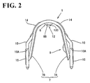
FIG. 2 is a rear view of the terminal, -
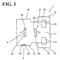
FIG. 3 is a plan view of the terminal, -
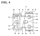
FIG. 4 is a bottom view of the terminal, -
FIG. 5 is a side view of the terminal, -
FIG. 6 is a side view in section of the terminal, -
FIG. 7 is a side view showing a state before the terminal is mounted on the coaxial cable (the terminal is shown in sectional side view), -
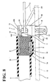
FIG. 8 is a side view in section when the terminal is mounted on the coaxial cable, -
FIG. 9 is a front view when the terminal is mounted on the coaxial cable, -
FIG. 10 is a plan view of the terminal according to another embodiment of the invention, -
FIG. 11 is a side view in section of the terminal according to the another embodiment, and -
FIG. 12 is a side view when the terminal according to the another embodiment is mounted on the coaxial cable. - Next, one embodiment of the invention is described in detail with reference to
FIGS. 1 to 9 . - First, the construction of a
coaxial cable 2 is described with reference toFIG. 7 . It should be noted that a side where acore 3 of thecoaxial cable 2 is exposed is referred to as a front side in the description of this embodiment. - The
coaxial cable 2 is comprised of four layers and thecore 3 is substantially centered inside. Thecore 3 is surrounded by aninner insulation coating 4; theinner insulation coating 4 is surrounded by a braided wire as ashield layer 5; and the braidedwire 5 is surrounded by anouter insulation coating 6 at the outermost side. These fourlayers 3 to 6 are substantially coaxially arranged. At an end of thecoaxial cable 2 to be connected with aterminal 1 for the coaxial cable (hereinafter, "terminal 1") to be described later, theouter insulation coating 6 is stripped, and the thus exposed braidedwire 5 is at least partly folded back preferably to be held in substantially close contact with the outer surface of theouter insulation coating 6 such that a base end of a folded section orportion 5A of the braidedwire 5 preferably substantially coincides with the front end of the remainingouter insulation coating 6. An exposed section of theinner insulation coating 4 is stripped up to a predetermined position before the foldedportion 5A, and thecore 3 projects from a leadingend 4A of the remaininginner insulation coating 4. It should be noted that the end of thecoaxial cable 2 thus processed may be referred to as "a stripped end" in the following description. - Next, the construction of the
terminal 1 is described.FIG. 1 is a front view of theterminal 1. Theterminal 1 is formed e.g. by bending a press-cut workpiece of an electrically conductive plate material or metal plate, and is to be mounted on the stripped end of thecoaxial cable 2. Theterminal 1 is substantially symmetrically formed with respect to the longitudinal axis of thecoaxial cable 2, and is provided at its rear side with abarrel portion 7 to be crimped or folded into connection with or crimped or substantially folded onto the foldedsection 5A of the braidedwire 5. Thebarrel portion 7 is comprised of a pair of transversely arrangedfastening pieces terminal 1 or preferably downward while being spaced apart from each other. - A biting
portion 8 projects inward of thebarrel portion 7 in the middle of the base ends of the fasteningpieces biting portion 8 is provided with a transversely extending slit or cut 8A and aslanted surface 8B in the form of an isosceles triangle which is embossed behind theslit 8A to bulge out inwardly, the front edge of theslanted surface 8B serving as alocking edge 8C. When thebiting portion 8 bites in or is inserted into the braidedwire 5, thelocking edge 8C restricts a backward displacement of thecoaxial cable 2 since it faces forward. Further, as shown inFIG. 3 , theright fastening piece 7A (the lower fastening piece inFIG. 3 ) is formed with abiting portion 9 similar to the above-mentionedbiting portion 8. Specifically, acut 9A is formed at a front side of the bitingportion 9, and a portion behind thecut 9A is embossed to bulge out inwardly of thebarrel portion 7 so as to serve as aslanted surface 9B and the front edge of the slanted surfaced 9B serves as alocking edge 9C. When thebarrel portion 7 is crimped into connection with thecoaxial cable 2, theright fastening piece 7A is crimped or folded first. At this time, the both bitingportions coaxial cable 2 in positions opposite to each other with respect to thecore 3 of thecoaxial cable 2. - At a front half of the
terminal 1, acover portion 11 substantially continuous with thebarrel portion 7 is provided. Thecover portion 11 substantially covers portions of theinner insulation coating 4 and thecore 3 preferably without being held in contact therewith when theterminal 1 is mounted on thecoaxial cable 2. A positioningportion 12 is provided at a boundary (a position more toward the front than the center of the terminal 1) of thecover portion 11 and thebarrel portion 7. The positioningportion 12 is comprised of aslit 12A extending at an angle different from 0° or 180°, preferably substantially normal to a longitudinal direction of theterminal 1 or preferably substantially transversely of theterminal 1, aslanted surface 12B formed by embossing a portion before theslit 12A to bulge out inwardly and having a shape of an isosceles triangle, and alocking edge 12C which is a rear edge of the slantedsurface 12B. Thispositioning portion 12 is shaped such that the lockingedge 12C is substantially opposed to the lockingedge 8C of the bitingportion 8 of the barrel portion 7 (see in combination withFIG. 6 ). Here, a projecting height or distance D of thepositioning portion 12 is longer or greater than a projecting height or distance E of the bitingportion 9. The bitingportion 8 and thepositioning portion 12 are preferably oriented substantially opposed to or facing each other, i.e. the bitingportion 8 and thepositioning portion 12 are embossed or oriented in directions such that the lockingedge 8C is arranged after theslanted surface 8B in an insertion direction of thecable 2 whereas the lockingedge 12C is arranged before theslanted surface 12B in the insertion direction. - Further, a pair of
leg portions 10 integrally or unitarily extend from the substantially opposite lateral edges of thecover portion 11. Theleg portions 10 are insertable into mount holes 16 of a printedcircuit board 13 to secure theterminal 1 to the printedcircuit board 13. It should be noted thatcontacts circuit board 13 near the edges of the mount holes 16 of the printedcircuit board 13 and in a position corresponding to where thecore 3 is welded, and are connected with unillustrated circuits. Further, a pair of steppedportions 10A are formed in positions of eachleg portion 10 near its middle position with respect to its height direction to narrow a width of theleg portion 10 along forward/backward directions from the front and rear sides. The steppedportions 10A are or can be brought substantially into contact with the upper surface of the printedcircuit board 13 to position theterminal 1. Eachleg portion 10 is formed with a vertically extendingembossed portion 15 below the steppedportions 10A in order to strengthen theleg portion 10 and preferably to lock theleg portion 10 in thecorresponding mount hole 16 when theterminal 1 is mounted on the printedcircuit board 13. It should be noted that a pair of embossedportions 14 are formed at boundaries of thecover portion 11 and theleg portions 10 to strengthen the plate material. - Next, the action and effects of this embodiment thus constructed are described with reference to
FIGS. 7 to 9 . - First, a heat
shrinkable tubing 18 is fitted on thecoaxial cable 2 in advance and moved away from the stripped end. Then, as shown inFIG. 7 , the stripped end is brought closer to the rear side of thebarrel portion 7 of theterminal 1 while thecoaxial cable 2 and theterminal 1 are so supported as to be aligned substantially straight. - As the
coaxial cable 2 is pushed forward in such a manner that the front end of the foldedsection 5A (the front end of the outer insulation coating 6) is not brought into contact with the lockingedge 8C of the bitingportion 8, the lockingedge 12C of thepositioning portion 12 comes into contact with the front end of theouter insulation coating 6 which is a starting position of the folded section of thebraided wire 5, thereby preventing any further insertion of thecoaxial cable 2. In this way, theterminal 1 can be automatically positioned on thecoaxial cable 2 with respect to its longitudinal direction. At this time, since the lockingedge 12C of thepositioning portion 12 projects higher than the lockingedge 8C of the bitingportion 8, thecoaxial cable 2 can be smoothly inserted without being interfered by the bitingportion 8. - In this state, the
barrel portion 7 is crimped into connection with thecoaxial cable 2. First, theright fastening piece 7A is crimped into connection with theouter insulation coating 6 while surrounding the foldedsection 5A of thebraided wire 5, and then thefastening piece 7B is so crimped as to surround theright fastening piece 7A. At this time, since the bitingportions braided wire 5 to lock thecoaxial cable 2, a function of preventing a disengagement of thebarrel portion 7 from thecoaxial cable 2 can be strengthened. After crimping thebarrel portion 7 in the above manner, thecover portion 11 covers thecore 3 without being held in contact therewith. After theterminal 1 is mounted on thecoaxial cable 2, the heatshrinkable tubing 18 fitted on thecoaxial cable 2 in advance is moved to the foldedsection 5A of thebraided wire 5 to cover it, and is shrunken by heating. - After the
terminal 1 is mounted at the end of thecoaxial cable 2 in this way, theleg portions 10 of theterminal 1 are mounted into the mount holes 16 of the printedcircuit board 13, and the leading ends of theleg portions 10 are connected to thecontact 19 e.g. by being soldered, resistance welded or by ultrasonic welding or the like connection at the underside of the printedcircuit board 13. It should be noted that thecore 3 is soldered after being bent to reach thecontact 20 of the printedcircuit board 13. - As described above, according to this embodiment, the positioning
portion 12 comes into engagement with a front end 6A of theouter insulation coating 6 of thecoaxial cable 2 when theterminal 1 is mounted on thecoaxial cable 2, thereby positioning theterminal 1 on thecoaxial cable 2 with respect to the longitudinal direction of thecoaxial cable 2, and thebarrel portion 7 is crimped into connection with the foldedsection 5A in this state. Accordingly, theterminal 1 can be stably mounted in the predetermined position of thecoaxial cable 2. Thus, theterminal 1 is stably mounted and thecore 3 is substantially covered by thecover portion 11 over a predetermined length, with the result that an electrical capacity between the terminal 1 and thecore 3 is stabilized to thereby provide stable high frequency characteristics. - Further, the
terminal 1 can be easily mounted on the printedcircuit board 13 by providing thecover portion 11 with theleg portions 10. - Next, another embodiment is described with reference to
FIGS. 10 to 12 . It should be noted that no description is given on the same or similar construction as the foregoing embodiment by identifying it by the same or similar reference numerals. - In this embodiment, a
positioning portion 30 is formed with a C-shapedcut 30A (inFIG. 10 , only a base portion 30B at the front end of thepositioning portion 30 is connected with thecover portion 11, and the remaining three sides are spaced from thecover portion 11 by thecut 30A), and an inner side of thecut 30A is bent inwardly of theterminal 1. The positioningportion 30 is bent to a position where it is arranged at an angle different from 0° or 180°, preferably substantially perpendicular to the extension of thecover portion 11, so that it can be held in surface-contact with the front end 6A of theouter insulation coating 6 of thecoaxial cable 2. Therefore, thecoaxial cable 2 can be more accurately positioned. - The embodiment thus constructed has the same action and effects as the foregoing embodiment.
- The present invention is not limited to the foregoing embodiments. For example, the following embodiment is also embraced by the technical scope of the present invention as defined in the claims.
- (1) Although the
terminal 1 is provided with theleg portions 10 and the bitingportions - (2) Although the invention has been described with reference to an embodiment in which the
terminal 1 is mounted on a shielded cable, it is to be understood that the invention may be applied to a cable having a core and an insulation coating only. - (3) Although the
coaxial cable 2 has been described with reference to ashield layer 5 in the form of braidedwires 5, it is to be understood that also other types of shield layers are possible e.g. those including alternatively or additionally a metal or conductive film. -
- 1 ...
- terminal for a coaxial cable
- 2 ...
- coaxial cable
- 3 ...
- core
- 4 ...
- inner insulation coating
- 5 ...
- braided wire
- 6 ...
- outer insulation coating
- 7 ...
- barrel portion
- 8, 9 ...
- biting portion
- 10 ...
- leg portion
- 11 ...
- cover portion
- 12, 30 ...
- positioning portion
- 13 ...
- printed circuit board
Claims (10)
- A terminal (1) mountable on a cable (2) comprised of an insulation coating (4), a core (3) projecting from the leading end of the insulation coating (4), comprising:a barrel portion (7) to be crimped into connection with a portion (5) of the cable (2), anda positioning portion (12; 30) to be substantially held in engagement with the cable (2) for positioning the terminal (1) on the cable (2) with respect to the longitudinal direction of the cable (2) before the barrel portion (7) is crimped into connection with the portion (5) of the cable (2),characterized by
a cover portion (11) substantially continuously extending from the barrel portion (7) so as to, when the terminal (1) is mounted on the cable (2), substantially cover the exposed core (3) without being held in contact therewith. - Use of a terminal according to claim 1 by mounting the terminal (1) on a coaxial cable (2) comprised of an inner insulation coating (4), a core (3) projecting from the leading end of the inner insulation coating (4), an outer insulation coating (6), and a shield layer (5) surrounding the inner insulation coating (4) and at least partly folded back to be brought substantially into close contact with the outer surface of the outer insulation coating (6),
wherein the barrel portion (7) is crimped into connection with a folded section (5A) of the shield layer (5) of the coaxial cable (2). - A terminal according to claim 1, wherein the cover portion (11) is integrally or unitarily formed with one or more leg portions (10) for mounting the terminal (1) on a printed circuit board (13).
- A terminal according to claim 3, wherein the leg portions (10) are provided with one or more embossed portions (14; 15) for strengthening the leg portions (10) and/or for locking the leg portions (10) in corresponding mount holes (16) of the circuit board (13).
- A terminal according to claim 3 or 4, wherein the leg portions (10) are provided with stepped portions (10A) for coming into engagement with the circuit board (13) upon insertion of the leg portions (10) into mount holes (16) of the printed circuit board (13).
- A terminal according to one or more of the preceding claims, wherein the barrel portion (7) is formed with at least one inward projecting biting portion (8; 9) for biting in a portion of the cable (2), preferably in the shield layer (5) thereof.
- A terminal according to claim 6, wherein a projecting height (E) of the biting portion (8; 9) is shorter than that (D) of the positioning portion (12; 30) lest the biting portion (8; 9) should interfere the insertion of the cable (2) into the terminal (1).
- A terminal according to claim 6 or 7, wherein the biting portion (8) and the positioning portion (12; 30) are arranged substantially opposing to each other along an arrangement direction of the cable (2).
- A terminal according to one or more of the claims 1 or 3 to 8, wherein the terminal (1) is constructed such that the cable (2) is insertable into the terminal (1) up to the cover portion (11) from a barrel portion (7) side along its longitudinal direction, and the positioning portion (12; 30) is formed by making a cut (12A; 30A) in the cover portion (11) and bending the cut portion and is engageable with a portion of the cable (2), preferably with the front end of the outer insulation coating (6) which is a starting position of the folded section (5A) of the shield layer (5).
- A method for mounting a terminal (1) according to one or more of the preceding claims on a cable (2) comprised of an insulation coating (4), a core (3) projecting from the leading end of the insulation coating (4), comprising the steps of:positioning the terminal (1) on the cable (2) with respect to the longitudinal direction of the cable (2) by bringing a positioning portion (12; 30) substantially in engagement with the cable (2), andcrimping a barrel portion (7) into connection with a portion (5) of the cable (2)characterized by
providing a cover portion (11) substantially continuously extending from the barrel portion (7) so as to substantially cover the exposed core (3) without being held in contact therewith.
Applications Claiming Priority (2)
| Application Number | Priority Date | Filing Date | Title |
|---|---|---|---|
| JP12896399 | 1999-05-10 | ||
| JP12896399A JP3419709B2 (en) | 1999-05-10 | 1999-05-10 | Coaxial cable terminal |
Publications (2)
| Publication Number | Publication Date |
|---|---|
| EP1052730A1 EP1052730A1 (en) | 2000-11-15 |
| EP1052730B1 true EP1052730B1 (en) | 2009-07-22 |
Family
ID=14997754
Family Applications (1)
| Application Number | Title | Priority Date | Filing Date |
|---|---|---|---|
| EP00109813A Expired - Lifetime EP1052730B1 (en) | 1999-05-10 | 2000-05-09 | A terminal for a cable and method for mounting a terminal |
Country Status (5)
| Country | Link |
|---|---|
| US (1) | US6372990B1 (en) |
| EP (1) | EP1052730B1 (en) |
| JP (1) | JP3419709B2 (en) |
| CN (1) | CN1124666C (en) |
| DE (1) | DE60042574D1 (en) |
Families Citing this family (20)
| Publication number | Priority date | Publication date | Assignee | Title |
|---|---|---|---|---|
| JP2005317298A (en) | 2004-04-28 | 2005-11-10 | Hirose Electric Co Ltd | Terminal for coaxial cable, and mounting structure and mounting method of the same |
| US7207806B2 (en) * | 2004-08-06 | 2007-04-24 | Broadcom Corporation | Low cost coaxial cable connection for wireless antennas |
| US7722362B2 (en) * | 2006-06-22 | 2010-05-25 | Watlow Electric Manufacturing Company | Sensor adaptor circuit housing incapsulating connection of an input connector with a wire |
| US7665890B2 (en) | 2006-06-22 | 2010-02-23 | Watlow Electric Manufacturing Company | Temperature sensor assembly and method of manufacturing thereof |
| JP4965226B2 (en) * | 2006-06-23 | 2012-07-04 | 株式会社オートネットワーク技術研究所 | Outer conductor terminal |
| US20110011638A1 (en) * | 2009-07-16 | 2011-01-20 | Paul Gemme | Shielding tape with edge indicator |
| US9728304B2 (en) | 2009-07-16 | 2017-08-08 | Pct International, Inc. | Shielding tape with multiple foil layers |
| US8882520B2 (en) | 2010-05-21 | 2014-11-11 | Pct International, Inc. | Connector with a locking mechanism and a movable collet |
| US8579658B2 (en) | 2010-08-20 | 2013-11-12 | Timothy L. Youtsey | Coaxial cable connectors with washers for preventing separation of mated connectors |
| TWI558007B (en) * | 2011-09-27 | 2016-11-11 | 緯創資通股份有限公司 | Connector for connecting a coaxial cable and a circuit board and related tranmission cable as well as assembly method therewith |
| EP2592914B1 (en) * | 2011-11-14 | 2015-05-06 | Continental Automotive GmbH | Clamping element |
| US9028276B2 (en) | 2011-12-06 | 2015-05-12 | Pct International, Inc. | Coaxial cable continuity device |
| US9004937B2 (en) * | 2012-08-30 | 2015-04-14 | Zierick Manufacturing Corporation | Surface mount/through-hole crimp piercing zipcord connector |
| CN104065021B (en) * | 2014-04-23 | 2016-08-17 | 李超 | A kind of cable vacation joint |
| EP3089272A1 (en) * | 2015-04-29 | 2016-11-02 | AGC Glass Europe | Glazing panel having an electrically conductive connector |
| US20190044258A1 (en) * | 2017-08-07 | 2019-02-07 | Commscope Technologies Llc | Cable connector block assemblies for base station antennas |
| CN109411967A (en) * | 2017-08-17 | 2019-03-01 | 春源科技(深圳)有限公司 | High-frequency RF connecting elements and its high-frequency RF wire jumper and plate terminal adapter |
| CN109273958B (en) * | 2018-09-13 | 2020-10-02 | 苏州热工研究院有限公司 | Tool for manufacturing nuclear-grade coaxial cable connector |
| JP7143207B2 (en) * | 2018-12-21 | 2022-09-28 | ヒロセ電機株式会社 | Coaxial cable connector with housing having paired crimp lugs |
| EP3788958A1 (en) | 2019-09-09 | 2021-03-10 | Heraeus Deutschland GmbH & Co KG | Electrical contact between electrically conducting polymer coated wires and electrically conducting substrates using wire bonding |
Family Cites Families (19)
| Publication number | Priority date | Publication date | Assignee | Title |
|---|---|---|---|---|
| US3383457A (en) * | 1966-04-05 | 1968-05-14 | Amp Inc | Connector means for connecting coaxial cable to a printed circuit board |
| US3670293A (en) * | 1970-08-20 | 1972-06-13 | Amp Inc | Shielded wire connectors |
| BE794947A (en) * | 1972-02-02 | 1973-08-02 | Raychem Corp | CONNECTION METHOD AND DEVICE |
| US4178054A (en) * | 1977-08-22 | 1979-12-11 | Amp Incorporated | Plug termination for coaxial cable |
| US4269469A (en) * | 1978-04-21 | 1981-05-26 | Souriau & Cie | Contact terminal connector |
| US5059140A (en) * | 1984-01-16 | 1991-10-22 | Stewart Stamping Corporation | Shielded plug and jack connector |
| GB8726934D0 (en) | 1987-11-18 | 1987-12-23 | Amp Gmbh | Electrical terminal assembly |
| JP2516089B2 (en) * | 1990-06-22 | 1996-07-10 | ヒロセ電機株式会社 | Connector wiring structure and method |
| JPH0727572Y2 (en) * | 1990-09-11 | 1995-06-21 | ヒロセ電機株式会社 | Electrical connector |
| JPH04214643A (en) * | 1990-12-12 | 1992-08-05 | Nec Kyushu Ltd | Resin-sealed semiconductor device |
| JPH05290249A (en) | 1992-04-06 | 1993-11-05 | Resortmation Eng:Kk | Merchandise bond bar code management system |
| JP2772322B2 (en) * | 1993-03-08 | 1998-07-02 | 矢崎総業株式会社 | Terminal connection structure of shielded wire |
| JP2899933B2 (en) * | 1993-03-24 | 1999-06-02 | 日本航空電子工業株式会社 | Cable connection contact, manufacturing method thereof, and connector device using cable connection contact |
| SG43073A1 (en) * | 1993-05-14 | 1997-10-17 | Molex Inc | Shielded electrical connector assembly |
| JPH08186414A (en) | 1994-12-27 | 1996-07-16 | Tokin Corp | Terminal pin |
| JP3202561B2 (en) * | 1995-11-17 | 2001-08-27 | 矢崎総業株式会社 | Male terminal fitting |
| JP3851711B2 (en) * | 1997-07-22 | 2006-11-29 | 株式会社オートネットワーク技術研究所 | Shield connector |
| DE29721752U1 (en) * | 1997-12-09 | 1998-02-12 | Siemens Ag | Crimp contact for plug systems |
| US6175080B1 (en) * | 1999-04-28 | 2001-01-16 | Tektronix, Inc. | Strain relief, pull-strength termination with controlled impedance for an electrical cable |
-
1999
- 1999-05-10 JP JP12896399A patent/JP3419709B2/en not_active Expired - Fee Related
-
2000
- 2000-05-09 US US09/567,692 patent/US6372990B1/en not_active Expired - Lifetime
- 2000-05-09 DE DE60042574T patent/DE60042574D1/en not_active Expired - Lifetime
- 2000-05-09 EP EP00109813A patent/EP1052730B1/en not_active Expired - Lifetime
- 2000-05-10 CN CN00107378A patent/CN1124666C/en not_active Expired - Fee Related
Also Published As
| Publication number | Publication date |
|---|---|
| CN1124666C (en) | 2003-10-15 |
| JP2000323213A (en) | 2000-11-24 |
| US6372990B1 (en) | 2002-04-16 |
| JP3419709B2 (en) | 2003-06-23 |
| EP1052730A1 (en) | 2000-11-15 |
| CN1273444A (en) | 2000-11-15 |
| DE60042574D1 (en) | 2009-09-03 |
Similar Documents
| Publication | Publication Date | Title |
|---|---|---|
| EP1052730B1 (en) | A terminal for a cable and method for mounting a terminal | |
| JP3015942B2 (en) | High-speed transmission line shield terminator | |
| US5190473A (en) | Microcoaxial cable connector | |
| KR100256927B1 (en) | System for terminating the shield of a high speed cable | |
| US5711686A (en) | System for terminating the shield of a high speed cable | |
| CA1060966A (en) | Plug-in terminal | |
| EP0793307A2 (en) | System for terminating the shield of a high speed cable | |
| JP3015940B2 (en) | High-speed transmission line shield terminator | |
| US8602831B2 (en) | Terminal having hanging parts from the sides and one end | |
| US7402073B2 (en) | Cable connector and method of connecting a cable with a cable connector | |
| EP0542075B1 (en) | Method of terminating miniature coaxial electrical connector and resulting terminated connector | |
| US4921439A (en) | Center wire trap terminal and connector | |
| KR100282632B1 (en) | System for terminating high speed cable shields | |
| EP1133003B1 (en) | Plug connector | |
| US5358426A (en) | Connector assembly for discrete wires of a shielded cable | |
| KR101521386B1 (en) | Method of connecting a cable with a cable connector | |
| US6483035B2 (en) | Protecting configuration for flat cables | |
| US5272807A (en) | Method of assembling a connector to electrical conductors | |
| JP3425634B2 (en) | Electrical connector with shield termination for high-speed cables | |
| US5186656A (en) | Miniature coaxial electrical connector | |
| EP0570832B1 (en) | Connector housing assembly for discrete wires | |
| US7052324B2 (en) | Plug connector having a damping element | |
| US6325681B1 (en) | Cable connector and contacts for cable connector | |
| JP2000350336A (en) | Solderless terminal |
Legal Events
| Date | Code | Title | Description |
|---|---|---|---|
| PUAI | Public reference made under article 153(3) epc to a published international application that has entered the european phase |
Free format text: ORIGINAL CODE: 0009012 |
|
| 17P | Request for examination filed |
Effective date: 20000531 |
|
| AK | Designated contracting states |
Kind code of ref document: A1 Designated state(s): DE FR GB IT |
|
| AX | Request for extension of the european patent |
Free format text: AL;LT;LV;MK;RO;SI |
|
| AKX | Designation fees paid |
Free format text: DE FR GB IT |
|
| 17Q | First examination report despatched |
Effective date: 20041011 |
|
| 17Q | First examination report despatched |
Effective date: 20041011 |
|
| GRAP | Despatch of communication of intention to grant a patent |
Free format text: ORIGINAL CODE: EPIDOSNIGR1 |
|
| RIN1 | Information on inventor provided before grant (corrected) |
Inventor name: SAITO, MASASHI, Inventor name: AOYAMA, MASAHIKO, Inventor name: KOIDE, TAKASHI, |
|
| GRAS | Grant fee paid |
Free format text: ORIGINAL CODE: EPIDOSNIGR3 |
|
| GRAA | (expected) grant |
Free format text: ORIGINAL CODE: 0009210 |
|
| AK | Designated contracting states |
Kind code of ref document: B1 Designated state(s): DE FR GB IT |
|
| REG | Reference to a national code |
Ref country code: GB Ref legal event code: FG4D |
|
| REF | Corresponds to: |
Ref document number: 60042574 Country of ref document: DE Date of ref document: 20090903 Kind code of ref document: P |
|
| PLBE | No opposition filed within time limit |
Free format text: ORIGINAL CODE: 0009261 |
|
| STAA | Information on the status of an ep patent application or granted ep patent |
Free format text: STATUS: NO OPPOSITION FILED WITHIN TIME LIMIT |
|
| 26N | No opposition filed |
Effective date: 20100423 |
|
| PGFP | Annual fee paid to national office [announced via postgrant information from national office to epo] |
Ref country code: DE Payment date: 20130515 Year of fee payment: 14 Ref country code: GB Payment date: 20130508 Year of fee payment: 14 |
|
| PGFP | Annual fee paid to national office [announced via postgrant information from national office to epo] |
Ref country code: IT Payment date: 20130423 Year of fee payment: 14 Ref country code: FR Payment date: 20130531 Year of fee payment: 14 |
|
| REG | Reference to a national code |
Ref country code: DE Ref legal event code: R119 Ref document number: 60042574 Country of ref document: DE |
|
| GBPC | Gb: european patent ceased through non-payment of renewal fee |
Effective date: 20140509 |
|
| REG | Reference to a national code |
Ref country code: FR Ref legal event code: ST Effective date: 20150130 |
|
| REG | Reference to a national code |
Ref country code: DE Ref legal event code: R119 Ref document number: 60042574 Country of ref document: DE Effective date: 20141202 |
|
| PG25 | Lapsed in a contracting state [announced via postgrant information from national office to epo] |
Ref country code: IT Free format text: LAPSE BECAUSE OF NON-PAYMENT OF DUE FEES Effective date: 20140509 Ref country code: DE Free format text: LAPSE BECAUSE OF NON-PAYMENT OF DUE FEES Effective date: 20141202 |
|
| PG25 | Lapsed in a contracting state [announced via postgrant information from national office to epo] |
Ref country code: GB Free format text: LAPSE BECAUSE OF NON-PAYMENT OF DUE FEES Effective date: 20140509 Ref country code: FR Free format text: LAPSE BECAUSE OF NON-PAYMENT OF DUE FEES Effective date: 20140602 |