EP1052650B1 - Cladding for use in nuclear reactors having improved resistance to cracking and corrosion - Google Patents
Cladding for use in nuclear reactors having improved resistance to cracking and corrosion Download PDFInfo
- Publication number
- EP1052650B1 EP1052650B1 EP00304016A EP00304016A EP1052650B1 EP 1052650 B1 EP1052650 B1 EP 1052650B1 EP 00304016 A EP00304016 A EP 00304016A EP 00304016 A EP00304016 A EP 00304016A EP 1052650 B1 EP1052650 B1 EP 1052650B1
- Authority
- EP
- European Patent Office
- Prior art keywords
- ppm
- amounts
- less
- nuclear fuel
- zirconium
- Prior art date
- Legal status (The legal status is an assumption and is not a legal conclusion. Google has not performed a legal analysis and makes no representation as to the accuracy of the status listed.)
- Expired - Lifetime
Links
Images

Classifications
-
- G—PHYSICS
- G21—NUCLEAR PHYSICS; NUCLEAR ENGINEERING
- G21C—NUCLEAR REACTORS
- G21C3/00—Reactor fuel elements and their assemblies; Selection of substances for use as reactor fuel elements
- G21C3/02—Fuel elements
- G21C3/04—Constructional details
- G21C3/16—Details of the construction within the casing
- G21C3/20—Details of the construction within the casing with coating on fuel or on inside of casing; with non-active interlayer between casing and active material with multiple casings or multiple active layers
-
- G—PHYSICS
- G21—NUCLEAR PHYSICS; NUCLEAR ENGINEERING
- G21C—NUCLEAR REACTORS
- G21C3/00—Reactor fuel elements and their assemblies; Selection of substances for use as reactor fuel elements
- G21C3/02—Fuel elements
- G21C3/04—Constructional details
- G21C3/06—Casings; Jackets
- G21C3/07—Casings; Jackets characterised by their material, e.g. alloys
-
- Y—GENERAL TAGGING OF NEW TECHNOLOGICAL DEVELOPMENTS; GENERAL TAGGING OF CROSS-SECTIONAL TECHNOLOGIES SPANNING OVER SEVERAL SECTIONS OF THE IPC; TECHNICAL SUBJECTS COVERED BY FORMER USPC CROSS-REFERENCE ART COLLECTIONS [XRACs] AND DIGESTS
- Y02—TECHNOLOGIES OR APPLICATIONS FOR MITIGATION OR ADAPTATION AGAINST CLIMATE CHANGE
- Y02E—REDUCTION OF GREENHOUSE GAS [GHG] EMISSIONS, RELATED TO ENERGY GENERATION, TRANSMISSION OR DISTRIBUTION
- Y02E30/00—Energy generation of nuclear origin
- Y02E30/30—Nuclear fission reactors
Definitions
- This invention relates broadly to improvements in nuclear fuel elements for use in the core of nuclear fission reactors and specifically, to improved nuclear fuel elements for use in boiling water reactors having improved stress corrosion cracking resistance and improved inner surface corrosion resistance.
- Standard parts of nuclear reactors are the fuel elements forming the core of the reactor that contains the nuclear fuel.
- the fuel elements may assume any one of a number of geometric cross-sections, the elements are comprised of nuclear fuel enclosed by cladding.
- the cladding is ideally corrosion resistant, non-reactive and heat conductive. Coolant, typically demineralized water, flows in the flow channels that are formed between the fuel elements to remove heat from the core.
- Coolant typically demineralized water
- One of the purposes of the cladding is to separate the nuclear material of the fuel from the coolant.
- Another purpose of the cladding is to minimize or prevent the radioactive fission products from contacting the coolant and thereby being spread throughout the primary cooling system.
- different cladding designs have failed by a number of failure mechanisms.
- the most common cladding materials include zirconium and alloys of zirconium, stainless steel, aluminum and its alloys, niobium and other materials. Of these, zirconium and its alloys have proven to be excellent materials for such purposes in water reactors because of material properties suited for cladding, including good heat conductivity, good strength and ductility, low neutron absorptivity and good resistance to corrosion.
- One composite system utilizes an inner lining of stainless steel metallurgically bonded to zirconium alloy.
- 3,969,186 which sets forth a composite consisting of refractory metals such as molybdenum, tungsten, rhenium, niobium and alloys of these materials in the form of a tube or foil of single or multiple layers or a coating on the internal surface of the cladding.
- refractory metals such as molybdenum, tungsten, rhenium, niobium and alloys of these materials in the form of a tube or foil of single or multiple layers or a coating on the internal surface of the cladding.
- the amount of iron alloyed with the zirconium is from about 0.2% to about 0.3% by weight; the amount of chromium is from about 0.05% to about 0.3% by weight; the total amount of iron plus chromium is from about 0.15% to about 0.3% by weight and wherein the ratio of the weights of iron to chromium is in the range of from about 1: 1 to about 4:1; and wherein the amount of copper is from about 0.02% to about 0.2% by weight.
- a particularly effective nuclear fuel element is comprised of a central core of a nuclear fuel material.
- the nuclear material may be any radioactive materials, such as the well known radioactive materials of uranium, plutonium, thorium and mixtures thereof.
- the central core of nuclear fuel material is surrounded by an elongated composite cladding comprised on an inner metallic barrier and an outer metallic tubular portion.
- the outer portion of the cladding is unchanged in design and function from the previous practices utilized in the nuclear reactor arts.
- the outer metallic tubular portion remains the standard, well-known materials conventionally used in cladding, and in particular, as outer portions of composite claddings.
- the outer metallic portion is selected from the group consisting of zirconium and its alloys, stainless steel, aluminum and its alloys, niobium and magnesium alloys.
- the inner metallic barrier is zirconium in which the amount of Fe is microalloyed with the zirconium in a controlled amount of iron from about 850-2500 parts per million by weight (ppm).
- the inner metallic barrier is metallurgically bonded to the outer metallic tubular portion, but unlike the outer metallic portion when comprised of zirconium or its alloys, is alloyed only with carefully controlled amounts of iron. Trace elements in an amount so as not to affect the character and nature of the inner metallic barrier may be present.
- the inner metallic barrier not only has greatly improved corrosion resistance over previous claddings and barriers but also improved stress corrosion cracking resistance, while the other important characteristics of the zirconium inner metallic barrier are unaffected.
- the barrier is ductile, compatible with the outer metallic tubular portion, but has low neutron absorptivity, yet is highly resistant to radiation hardening while maintaining good heat transfer characteristics. It is believed that the present invention improves the ability of the fuel element to operate normally in the failed condition, that is, with the failure of the outer cladding due to primary defects developed as a result of stress corrosion or fretting, but without developing secondary long axial cracks along the inner barrier.
- the inner metallic barrier has sufficient corrosion resistance such that it will continue to provide an effective barrier when exposed to the nuclear fuel and the by-products of nuclear fission as well as the coolant, which may include demineralized water, steam and/or moderators.
- the life expectancy of the fuel element is increased, even after failure of the outer cladding, due to the ability of the inner metallic barrier to slow down the formation of corrosion products (hydrides) upon contact with coolant.
- a partially cutaway sectional view-of a nuclear fuel assembly 10 consists of a tubular flow channel 11 of generally square cross-section provided in its upper end with a lifting bail 12, and at its lower end, with a nose piece (not shown due to the lower portion of assembly 10 being omitted).
- the upper end of channel 11 is open at outlet 13 and the lower end of the nose piece is provided with cooling flow openings.
- An array of fuel elements or rods 14 is enclosed in the channel 11 and supported therein by means of an upper end plate 15 and a lower end plate (not shown due to the lower portion being omitted).
- the liquid coolant ordinarily enters through the openings in the lower end of the nose piece, passes upwardly around fuel elements 14, and discharges through the upper outlet 13 at an elevated temperature in a partially vaporized condition for boiling reactors or in an unvaporized condition for pressurized water reactors.
- the nuclear fuel elements or rods 14 are sealed at their ends by means of end plugs 18 welded to the composite cladding 17, which may include studs 19 to facilitate the mounting of the fuel rod in the assembly.
- a void space or plenum 20 is provided at one end of the element to permit longitudinal expansion of the fuel material and accumulation of gases released from the fuel material.
- a nuclear fuel material retainer means 24 in the form of a helical member if positioned within space 20 to provide restraint against the axial movement of the pellet column, especially during handling and transportation of the fuel element.
- the fuel element is designed to provide excellent thermal contact between the cladding and the fuel material, a minimum amount of parasitic neutron absorption, and resistance to bowing and vibration which is occasionally caused by flow of the coolant at high velocity.
- a nuclear fuel element or rod 14 constructed according to the teachings of this invention is shown in a partial section in Fig. 1.
- the fuel element includes a core or central cylindrical portion of nuclear fuel material 16, here shown as a plurality of fuel pellets or fissionable and/or fertile materials positioned within a structural composite cladding of container 17.
- the fuel pellets may be of various shapes, such as cylindrical pellets or spheres.
- different fuel forms such as particulate fuel, may be used.
- the physical form of the fuel is immaterial to this invention.
- Various nuclear fuel materials may be used including uranium compounds, plutonium compounds, thorium compounds, and mixtures thereof.
- the preferred fuel is uranium dioxide or a mixture comprising uranium dioxide and plutonium dioxide.
- the nuclear fuel material 16 forming the central core of the fuel element 14 is surrounded by composite cladding 17, which, in this invention, is also referred to as a composite cladding container.
- the composite cladding container generally elongated in shape, encloses the fissile core.
- a gap 23 is optional between the core and the composite cladding 17 and may or may not be present.
- the composite cladding container has an external substrate or outer metallic tubular portion 21 selected from conventional cladding materials such as stainless steel and zirconium alloys.
- the outer metallic tubular portion 21 is a zirconium alloy such as Zircaloy-2, currently the preferred alloy in the outer portion, Zircaloy-4 and other zirconium alloy improvements.
- Metallurgically bonded to the outer metallic tubular portion of the container is an inner metallic barrier. This inner metallic barrier is positioned to prevent contact between the nuclear fuel and the outer metallic tubular portion.
- the inner metallic barrier is comprised of commercially pure zirconium microalloyed with iron (Fe). The amount of Fe is carefully controlled so as not to be under a lower value of 850 parts per million (ppm) and not to exceed an upper value of 2500 ppm. As set forth in U.S. Patent No.
- the discovery of this invention has been that by controlling the amount of Fe as a microalloyed addition to the commercially pure zirconium, an inner metallic barrier having a beneficial balance between stress corrosion crack resistance and corrosion resistance resulting in an improved alloy can be produced. While iron has been present as a trace or tramp element in the past, the amount of iron has only been controlled as a maximum permissible amount, so that erratic results in performance occurred because there was no appreciation of controlling the composition of the Fe within the limits set forth by the present invention to achieve the improved beneficial balance between stress corrosion crack resistance and corrosion resistance.
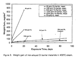
- Fig. 3 is a graph of the corrosion resistance of zirconium having varying amounts of Fe content as measured by weight gain over a period of time in 400°C (750°F) steam as set forth by a modified test based on the ASTM G2 Steam Test. The modification consists of extending the time of the ASTM G2 Stream Test.
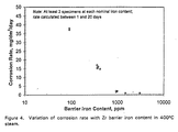
- Fig. 4 is a graph showing the effect of increasing iron content on the corrosion rate of Zr in 400°C steam. Clearly, there is a correlation between Fe content and the corrosion of Zr in 400°C steam.
- the corrosion rate of the Zr drops from about 35 mg/dm 2 /day to about 15 mg/dm 2 /day.
- the corrosion rate is significantly reduced, exhibiting a decay approaching 0 asymptotically.
- small increases in iron from about 360 ppm to 940 ppm significantly reduce the corrosion of the Zr.
- the improvement is a diminishing function of increased Fe. It appears that the saturation in corrosion rate improvement occurs at about 1500 ppm.
- the resistance of Zr to stress corrosion cracking is also related to the Fe content of the Zr.
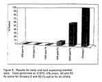
- Resistance to stress corrosion cracking is measured by a test using an expanding mandrel in an iodine environment.
- the test simulates the ability of a fuel rod to resist the in-reactor failure mechanism called pellet cladding interaction (PCI) and is referred to as PCI resistance testing.
- PCI resistance testing The test is performed using a ramp and hold expanding mandrel, with a 4% strain rate at 315°C (662°F).
- PCI resistance testing The test is performed using a ramp and hold expanding mandrel, with a 4% strain rate at 315°C (662°F).
- Fig. 5 and the data of Table 1 indicate that at and below about 1000 ppm Fe the PCI resistance is perfect, which is to say that no tests produced failure. At about 1500 ppm Fe, there is a transition to decreasing PCI resistance. At about 3000 ppm Fe, about 60% of the tests produced failure, which is an unsatisfactory result.
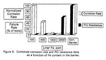
- Fig. 6 is a graph that depicts both the corrosion rate and the PCI resistance as a function of the Fe content of the barrier. It can be seen from this graph that Fe in a range of from about 1000 to about 2000 ppm produces both acceptable corrosion rates and tolerable PCI resistance.
- another embodiment of the invention will include Fe in the range of about 850-2000 ppm microalloyed with commercially pure Zr.
- Fe is included in the range of about 1000-2000 ppm. The most preferred embodiment includes 1000 +/- 150 ppm Fe-microalloyed with Zr.
- the Zr microalloyed with Fe will retain the ductility that is desirable in an inner metallic barrier. Because the Fe is controlled in microalloyed amounts, it retains its low neutron absorptivity and good heat transfer characteristics yet is highly resistant to radiation hardening. Ideally, the Zirconium microalloyed with Fe is metallurgically bonded to the outer metallic tubular portion 21, preferably Zircaloy-2, but is recrystallized having a grain size in the range of ASTM 9 to ASTM 12.
- the inner metallic barrier 22 typically and preferably comprises between about 10% to about 20% of the total thickness of the composite cladding 17.
- the thickness of inner metallic barrier 22 can be varied outside this prescribed thickness range as long as neither the integrity of the outer metallic tubular portion 21 nor the ability of the inner metallic portion 22 to function as a barrier is adversely affected.
- the composite cladding 17 can be manufactured by any of the well-known prior art methods for bonding an inner barrier of zirconium sponge to an outer barrier of, for example, stainless steel or Zircaloy.
Landscapes
- Engineering & Computer Science (AREA)
- Physics & Mathematics (AREA)
- Plasma & Fusion (AREA)
- General Engineering & Computer Science (AREA)
- High Energy & Nuclear Physics (AREA)
- Metallurgy (AREA)
- Monitoring And Testing Of Nuclear Reactors (AREA)
- Other Surface Treatments For Metallic Materials (AREA)
Description
- This invention relates broadly to improvements in nuclear fuel elements for use in the core of nuclear fission reactors and specifically, to improved nuclear fuel elements for use in boiling water reactors having improved stress corrosion cracking resistance and improved inner surface corrosion resistance.
- Standard parts of nuclear reactors are the fuel elements forming the core of the reactor that contains the nuclear fuel. Although the fuel elements may assume any one of a number of geometric cross-sections, the elements are comprised of nuclear fuel enclosed by cladding. The cladding is ideally corrosion resistant, non-reactive and heat conductive. Coolant, typically demineralized water, flows in the flow channels that are formed between the fuel elements to remove heat from the core. One of the purposes of the cladding is to separate the nuclear material of the fuel from the coolant. Another purpose of the cladding is to minimize or prevent the radioactive fission products from contacting the coolant and thereby being spread throughout the primary cooling system. However, over time different cladding designs have failed by a number of failure mechanisms.
- In order to accomplish these and other purposes, various materials and combinations of materials have been used in the cladding. The most common cladding materials include zirconium and alloys of zirconium, stainless steel, aluminum and its alloys, niobium and other materials. Of these, zirconium and its alloys have proven to be excellent materials for such purposes in water reactors because of material properties suited for cladding, including good heat conductivity, good strength and ductility, low neutron absorptivity and good resistance to corrosion. One composite system utilizes an inner lining of stainless steel metallurgically bonded to zirconium alloy. The disadvantage of this system is that the stainless steel develops brittle phases that ultimately crack, allowing the by-products of the fission to contact the zirconium alloy cladding, initiating the deterioration of the zirconium alloy outer cladding. Furthermore, the stainless steel layer has a neutron absorption penalty of ten to fifteen times the penalty for a zirconium alloy of the same thickness.
A solution to the problem of cladding failure is set forth in U.S. Patent No. 3,969,186 which sets forth a composite consisting of refractory metals such as molybdenum, tungsten, rhenium, niobium and alloys of these materials in the form of a tube or foil of single or multiple layers or a coating on the internal surface of the cladding. - Still another solution to the problem is set forth in U.S. Patent No. 4,045,288 that teaches the use of a composite cladding of zirconium alloy substrate with a sponge zirconium liner. The concept is that the commercially pure, soft, ductile zirconium liner minimizes the localized strain that the outer cladding is subject to. However, if a breach in the outer cladding should occur, allowing water and/or steam to enter the fuel rod, the zirconium liner tends to oxidize rapidly.
- Yet another approach to the problem of cladding failure set forth in U.S. Application No. 06/374,052 filed May 3, 1982, assigned to the assignee of the present application, which corresponds to GB-A-2 119 559, teaches using a composite cladding consisting of a dilute zirconium alloy inner liner metallurgically bonded to conventional cladding materials such as zirconium alloy claddings. The dilute zirconium alloy inner liner includes at least one metal alloyed with the zirconium selected from the group consisting of iron, chromium, iron plus chromium and copper. The amount of iron alloyed with the zirconium is from about 0.2% to about 0.3% by weight; the amount of chromium is from about 0.05% to about 0.3% by weight; the total amount of iron plus chromium is from about 0.15% to about 0.3% by weight and wherein the ratio of the weights of iron to chromium is in the range of from about 1: 1 to about 4:1; and wherein the amount of copper is from about 0.02% to about 0.2% by weight.
- While advances have been made in the area of improving the performance of claddings, corrosion and brittle splitting of the cladding due to interactions of the cladding, the nuclear fuel, the fission products and the coolant continues to be a problem even with the improved systems.
- A particularly effective nuclear fuel element is comprised of a central core of a nuclear fuel material. The nuclear material may be any radioactive materials, such as the well known radioactive materials of uranium, plutonium, thorium and mixtures thereof.
- In accordance with one embodiment of the invention, the central core of nuclear fuel material is surrounded by an elongated composite cladding comprised on an inner metallic barrier and an outer metallic tubular portion. The outer portion of the cladding is unchanged in design and function from the previous practices utilized in the nuclear reactor arts. The outer metallic tubular portion remains the standard, well-known materials conventionally used in cladding, and in particular, as outer portions of composite claddings. The outer metallic portion is selected from the group consisting of zirconium and its alloys, stainless steel, aluminum and its alloys, niobium and magnesium alloys.
- The inner metallic barrier is zirconium in which the amount of Fe is microalloyed with the zirconium in a controlled amount of iron from about 850-2500 parts per million by weight (ppm). The inner metallic barrier is metallurgically bonded to the outer metallic tubular portion, but unlike the outer metallic portion when comprised of zirconium or its alloys, is alloyed only with carefully controlled amounts of iron. Trace elements in an amount so as not to affect the character and nature of the inner metallic barrier may be present.
- Surprisingly, by carefully controlling the amount of iron present in the zirconium, it has been discovered that the inner metallic barrier not only has greatly improved corrosion resistance over previous claddings and barriers but also improved stress corrosion cracking resistance, while the other important characteristics of the zirconium inner metallic barrier are unaffected. The barrier is ductile, compatible with the outer metallic tubular portion, but has low neutron absorptivity, yet is highly resistant to radiation hardening while maintaining good heat transfer characteristics. It is believed that the present invention improves the ability of the fuel element to operate normally in the failed condition, that is, with the failure of the outer cladding due to primary defects developed as a result of stress corrosion or fretting, but without developing secondary long axial cracks along the inner barrier. The inner metallic barrier has sufficient corrosion resistance such that it will continue to provide an effective barrier when exposed to the nuclear fuel and the by-products of nuclear fission as well as the coolant, which may include demineralized water, steam and/or moderators. The life expectancy of the fuel element is increased, even after failure of the outer cladding, due to the ability of the inner metallic barrier to slow down the formation of corrosion products (hydrides) upon contact with coolant.
- The invention will now be described in greater detail, by way of example, with reference to the drawings, in which:
- Fig. 1 is a partial cutaway section of a nuclear fuel assembly containing nuclear fuel elements constructed according to the teaching of this invention;
- Fig. 2 is an enlarged transverse cross-sectional view of the nuclear fuel element of Fig. 1, illustrating the teaching of this invention.
- Fig. 3 is a graph of the corrosion of zirconium having varying amounts of iron over an exposure time in days;
- Fig. 4 is a graph of the corrosion rate of zirconium versus microalloyed amounts of iron;
- Fig. 5 is a graph depicting the results of Pellet Cladding Interaction (PC1) resistance testing of zirconium microalloyed with varying amounts of iron; and
- Fig. 6 is a graph depicting the combined corrosion rate the Pellet Cladding Interaction (PCI) resistance testing results of a function of microalloyed concentration of iron in zirconium.
- Referring now more particularly to Fig. 1, there is shown a partially cutaway sectional view-of a
nuclear fuel assembly 10. Thisfuel assembly 10 consists of a tubular flow channel 11 of generally square cross-section provided in its upper end with alifting bail 12, and at its lower end, with a nose piece (not shown due to the lower portion ofassembly 10 being omitted). The upper end of channel 11 is open at outlet 13 and the lower end of the nose piece is provided with cooling flow openings. An array of fuel elements orrods 14 is enclosed in the channel 11 and supported therein by means of anupper end plate 15 and a lower end plate (not shown due to the lower portion being omitted). The liquid coolant ordinarily enters through the openings in the lower end of the nose piece, passes upwardly aroundfuel elements 14, and discharges through the upper outlet 13 at an elevated temperature in a partially vaporized condition for boiling reactors or in an unvaporized condition for pressurized water reactors. - The nuclear fuel elements or
rods 14 are sealed at their ends by means ofend plugs 18 welded to thecomposite cladding 17, which may includestuds 19 to facilitate the mounting of the fuel rod in the assembly. A void space orplenum 20 is provided at one end of the element to permit longitudinal expansion of the fuel material and accumulation of gases released from the fuel material. A nuclear fuel material retainer means 24 in the form of a helical member if positioned withinspace 20 to provide restraint against the axial movement of the pellet column, especially during handling and transportation of the fuel element. - The fuel element is designed to provide excellent thermal contact between the cladding and the fuel material, a minimum amount of parasitic neutron absorption, and resistance to bowing and vibration which is occasionally caused by flow of the coolant at high velocity.
- A nuclear fuel element or
rod 14 constructed according to the teachings of this invention is shown in a partial section in Fig. 1. The fuel element includes a core or central cylindrical portion ofnuclear fuel material 16, here shown as a plurality of fuel pellets or fissionable and/or fertile materials positioned within a structural composite cladding ofcontainer 17. In some cases, the fuel pellets may be of various shapes, such as cylindrical pellets or spheres. In other cases, different fuel forms, such as particulate fuel, may be used. The physical form of the fuel is immaterial to this invention. Various nuclear fuel materials may be used including uranium compounds, plutonium compounds, thorium compounds, and mixtures thereof. The preferred fuel is uranium dioxide or a mixture comprising uranium dioxide and plutonium dioxide. Referring now to Fig. 2, thenuclear fuel material 16 forming the central core of thefuel element 14 is surrounded bycomposite cladding 17, which, in this invention, is also referred to as a composite cladding container. The composite cladding container, generally elongated in shape, encloses the fissile core. Agap 23 is optional between the core and thecomposite cladding 17 and may or may not be present. The composite cladding container has an external substrate or outer metallictubular portion 21 selected from conventional cladding materials such as stainless steel and zirconium alloys. In the preferred embodiment of this invention, the outer metallictubular portion 21 is a zirconium alloy such as Zircaloy-2, currently the preferred alloy in the outer portion, Zircaloy-4 and other zirconium alloy improvements. Metallurgically bonded to the outer metallic tubular portion of the container is an inner metallic barrier. This inner metallic barrier is positioned to prevent contact between the nuclear fuel and the outer metallic tubular portion. The inner metallic barrier is comprised of commercially pure zirconium microalloyed with iron (Fe). The amount of Fe is carefully controlled so as not to be under a lower value of 850 parts per million (ppm) and not to exceed an upper value of 2500 ppm. As set forth in U.S. Patent No. 4,200,492, production of commercially pure zirconium having trace impurities is well-known. The normal range of these impurities include aluminum (Al) in the amounts of 75 ppm or less; boron (B) in the amounts of 0.4 ppm or less; cadmium (Cd) in the amounts of 0.4 ppm or less; carbon (C) in the amounts of 270 ppm or less; chromium (Cr) in the amounts of 200 ppm or less; cobalt (Co) in the amounts of 20 ppm or less; copper (Cu) in the amounts of 50 ppm or less; hafnium (Hf) in the amounts of 100 ppm or less; hydrogen (H) in the amounts of 25 ppm or less; magnesium (Mg) in the amounts of 20 ppm or less; manganese (Mn) in the amounts of 50 ppm or less; molybdenum (Mo) in the amounts of 50 ppm or less; nickel (Ni) in the amounts of 70 ppm or less; niobium (Nb) in the amounts of 100 ppm or less, nitrogen (N) in the amounts of 80 ppm or less; tungsten (W) in the amounts of 100 ppm or less; silicon (Si) in the amounts of 120 ppm or less; tin (Sn) in the amounts of 50 ppm or less; titanium (Ti) in the amounts of 50 ppm or less and uranium in the amounts of 3.5 ppm or less. The prior art practice has treated Fe as a trace element which may be present in the amounts of 1500 ppm or less. - The discovery of this invention has been that by controlling the amount of Fe as a microalloyed addition to the commercially pure zirconium, an inner metallic barrier having a beneficial balance between stress corrosion crack resistance and corrosion resistance resulting in an improved alloy can be produced. While iron has been present as a trace or tramp element in the past, the amount of iron has only been controlled as a maximum permissible amount, so that erratic results in performance occurred because there was no appreciation of controlling the composition of the Fe within the limits set forth by the present invention to achieve the improved beneficial balance between stress corrosion crack resistance and corrosion resistance.
- It has been discovered that the corrosion resistance and the stress corrosion crack resistance of commercially pure zirconium can be balanced by micro alloying it with Fe in the amounts from about 850 ppm to about 2500 ppm. The incidental impurities as set forth above can remain at the levels as previously set forth without adversely affecting the beneficial aspects of the present invention.
- Referring now to Fig. 3 and 4, the corrosion resistance of Zr is related to the Fe content present in the Zr. Fig. 3 is a graph of the corrosion resistance of zirconium having varying amounts of Fe content as measured by weight gain over a period of time in 400°C (750°F) steam as set forth by a modified test based on the ASTM G2 Steam Test. The modification consists of extending the time of the ASTM G2 Stream Test. Fig. 4 is a graph showing the effect of increasing iron content on the corrosion rate of Zr in 400°C steam. Clearly, there is a correlation between Fe content and the corrosion of Zr in 400°C steam. Between about 100 and 400 ppm Fe, the corrosion rate of the Zr drops from about 35 mg/dm2/day to about 15 mg/dm2/day. At about 800 ppm to about 850 ppm Fe the corrosion rate is significantly reduced, exhibiting a decay approaching 0 asymptotically. As indicated by Fig. 3, small increases in iron from about 360 ppm to 940 ppm significantly reduce the corrosion of the Zr. Above about 940 ppm, although increasing the Fe content improves the corrosion resistance of the Zr slightly, the improvement is a diminishing function of increased Fe. It appears that the saturation in corrosion rate improvement occurs at about 1500 ppm. Thus, it is important to maintain the Fe levels in the Zr above the minimum amounts of about 850 ppm and preferably above about 1000 ppm and most preferably above about 1500 ppm in order to take advantage of the corrosion resistance of the microalloyed Fe. As the amount of microalloyed Fe in Zr drops below about 850 ppm, the corrosion resistance of the inner barrier begins to deteriorate dramatically. Thus, it can be seen that the life of an inner barrier having less than the critical amount of Fe will be shortened, resulting in a failure.
- Referring now to Fig. 5, the resistance of Zr to stress corrosion cracking is also related to the Fe content of the Zr. Resistance to stress corrosion cracking is measured by a test using an expanding mandrel in an iodine environment. The test simulates the ability of a fuel rod to resist the in-reactor failure mechanism called pellet cladding interaction (PCI) and is referred to as PCI resistance testing. The test is performed using a ramp and hold expanding mandrel, with a 4% strain rate at 315°C (662°F). There is no standard industry test, although various tests are used in the industry. The Assignee of the present invention has found that the expanding mandrel test as set forth above, can discriminate between and among varying stress corrosion cracking susceptibility of alloys. When the stress-strain conditions generated by various industry testing techniques reflect actual fuel rod conditions, similar discrimination should result from such tests. Fig. 5 and the data of Table 1 indicate that at and below about 1000 ppm Fe the PCI resistance is perfect, which is to say that no tests produced failure. At about 1500 ppm Fe, there is a transition to decreasing PCI resistance. At about 3000 ppm Fe, about 60% of the tests produced failure, which is an unsatisfactory result.
TABLE 1 Material 400 ppm Fe Barrier 940 ppm Fe Barrier 1000 ppm Fe Barrier 1500 ppm Fe Barrier 3000 ppm Fe Barrier Zircaloy-2 Non-Barrier Zircaloy-2 Non-Barrier Failure % 0 0 0 10 60 100 100 # Tests 3 10 10 10 10 7 9 Iodine Pressure (Pa) 50 50 50 50 50 40 50 - From these two tests, it can be seen that even though cracking resistance is excellent below about 850 ppm Fe, the corrosion resistance at this Fe level is unacceptable. At or above 850 ppm Fe, the corrosion level is acceptable. At about 1500 ppm Fe, the crack resistance begins to deteriorate, trending towards unacceptable levels, even though the corrosion resistance is excellent. Thus, even though there may be some small amount of cracking at about 2000 ppm Fe, it is tolerable since it is not accompanied by corrosion, which would provide a combined failure mechanism, exacerbating the failure of the barrier protection. Crack resistance continues to deteriorate and it can be seen from the graphs of Fig. 5 and 6 that it becomes unacceptable in the range of Fe between about 2500 and 3000 ppm.
- Fig. 6 is a graph that depicts both the corrosion rate and the PCI resistance as a function of the Fe content of the barrier. It can be seen from this graph that Fe in a range of from about 1000 to about 2000 ppm produces both acceptable corrosion rates and tolerable PCI resistance. Referring to Table 1 and Figs 3-6, since a slight increase in PCI cracking can be tolerated, another embodiment of the invention will include Fe in the range of about 850-2000 ppm microalloyed with commercially pure Zr. In a preferred embodiment of the invention, Fe is included in the range of about 1000-2000 ppm. The most preferred embodiment includes 1000 +/- 150 ppm Fe-microalloyed with Zr. The Zr microalloyed with Fe will retain the ductility that is desirable in an inner metallic barrier. Because the Fe is controlled in microalloyed amounts, it retains its low neutron absorptivity and good heat transfer characteristics yet is highly resistant to radiation hardening. Ideally, the Zirconium microalloyed with Fe is metallurgically bonded to the outer metallic
tubular portion 21, preferably Zircaloy-2, but is recrystallized having a grain size in the range of ASTM 9 toASTM 12. The innermetallic barrier 22 typically and preferably comprises between about 10% to about 20% of the total thickness of thecomposite cladding 17. However, the thickness of innermetallic barrier 22 can be varied outside this prescribed thickness range as long as neither the integrity of the outer metallictubular portion 21 nor the ability of the innermetallic portion 22 to function as a barrier is adversely affected. Thecomposite cladding 17 can be manufactured by any of the well-known prior art methods for bonding an inner barrier of zirconium sponge to an outer barrier of, for example, stainless steel or Zircaloy.
Claims (7)
- A nuclear fuel element (10), comprising:a central core of a body of nuclear fuel material (16) selected from the group consisting of compounds of uranium, plutonium, thorium, and mixtures thereof, and an elongated container (17) having a hollow central bore, the container (17) comprised of an outer metallic tubular portion (2 1) and an inner metallic barrier (22) metallurgically bonded to the outer metallic tubular portion (2 1), characterised by the inner metallic barrier (22) having a combination of crack resistance consisting essentially of commercially pure zirconium microalloyed with iron in the range of 850-1500ppm and the balance zirconium and incidental impurities.
- The nuclear fuel element (10) of claim 1 in which the inner metallic barrier (22) includes iron in a range from 1000-1500 ppm is alloyed with zirconium.
- The nuclear fuel element (10) of claim 1 or 2 wherein the inner metallic barrier (22) is recrystallized, having a grain size in the range of ASTM 9 to ASTM 11.
- The nuclear fuel element (10) of claim 1 or 2 wherein the inner metallic barrier (22) is recrystallized, having a grain size in the range of ASTM 9 to ASTM 12.
- The nuclear fuel element of claim 1 wherein the zirconium microalloyed with iron is Zircaloy-2.
- The nuclear fuel element of claim 1 or 5 wherein the inner metallic barrier (22) comprises 10 to 20% of the total composite container (17) thickness.
- The nuclear fuel element of claim 1 wherein the alloy of zirconium microalloyed with Fe has Pellet Cladding Interaction resistance in testing at 315°C with a maximum failure rate of about 10% and a maximum corrosion rate in 400°C steam as measured by the modified ASTM G2 steam test of about 2 mg/dm2/day, and including incidental impurities of AI in the amounts of 5 ppm or less, B in the amounts of 0.4 ppm or less, Cd in the amounts of 0.4 ppm or less, C in the amounts of 270 ppm or less, Cr in the amounts of 200 ppm or less, Co in the amounts of 20 ppm or less, Cu in the amounts of 50 ppm or less, Hf in the amounts of 100 ppm or less, H in the amounts of 25 ppm or less, Mg in the amounts of 20 ppm or less, Mn in the amounts of 50 ppm or less, Mo in the amounts of 50 ppm or less, Ni in the amounts of 70 ppm or less, Nb in the amounts of 100 ppm or less, N in the amounts of 80 ppm or less, W in the amounts of 100 ppm or less, Si in the amounts of 120 ppm or less, Sn in the amounts of 50 ppm or less, Ti in the amounts of 50 ppm or less and U in the amounts of 3.5 ppm or less.
Applications Claiming Priority (2)
| Application Number | Priority Date | Filing Date | Title |
|---|---|---|---|
| US09/312,021 US6243433B1 (en) | 1999-05-14 | 1999-05-14 | Cladding for use in nuclear reactors having improved resistance to stress corrosion cracking and corrosion |
| US312021 | 1999-05-14 |
Publications (2)
| Publication Number | Publication Date |
|---|---|
| EP1052650A1 EP1052650A1 (en) | 2000-11-15 |
| EP1052650B1 true EP1052650B1 (en) | 2006-11-15 |
Family
ID=23209522
Family Applications (1)
| Application Number | Title | Priority Date | Filing Date |
|---|---|---|---|
| EP00304016A Expired - Lifetime EP1052650B1 (en) | 1999-05-14 | 2000-05-12 | Cladding for use in nuclear reactors having improved resistance to cracking and corrosion |
Country Status (5)
| Country | Link |
|---|---|
| US (2) | US6243433B1 (en) |
| EP (1) | EP1052650B1 (en) |
| JP (1) | JP2001066390A (en) |
| DE (1) | DE60031804T2 (en) |
| ES (1) | ES2275473T3 (en) |
Families Citing this family (20)
| Publication number | Priority date | Publication date | Assignee | Title |
|---|---|---|---|---|
| US6714618B1 (en) * | 1997-11-28 | 2004-03-30 | General Electric Company | Temperature-based method for controlling the amount of metal applied to metal oxide surfaces to reduce corrosion and stress corrosion cracking |
| SE525455C2 (en) * | 2002-06-07 | 2005-02-22 | Westinghouse Atom Ab | Process, use and device for nuclear fuel enclosure pipes as well as fuel cartridge for a nuclear boiler water reactor |
| US7194980B2 (en) * | 2003-07-09 | 2007-03-27 | John Stuart Greeson | Automated carrier-based pest control system |
| US8043448B2 (en) * | 2004-09-08 | 2011-10-25 | Global Nuclear Fuel-Americas, Llc | Non-heat treated zirconium alloy fuel cladding and a method of manufacturing the same |
| US9139895B2 (en) * | 2004-09-08 | 2015-09-22 | Global Nuclear Fuel—Americas, LLC | Zirconium alloy fuel cladding for operation in aggressive water chemistry |
| JP4975390B2 (en) * | 2006-07-21 | 2012-07-11 | 株式会社グローバル・ニュークリア・フュエル・ジャパン | Method of manufacturing fuel cladding for high burnup |
| EA015019B1 (en) | 2007-12-26 | 2011-04-29 | Ториум Пауэр Инк. | Nuclear reactor (variants), fuel assembly consisting of driver-breeding modules for a nuclear reactor (variants) and a fuel cell for a fuel assembly |
| US8116423B2 (en) | 2007-12-26 | 2012-02-14 | Thorium Power, Inc. | Nuclear reactor (alternatives), fuel assembly of seed-blanket subassemblies for nuclear reactor (alternatives), and fuel element for fuel assembly |
| EP3032541B1 (en) | 2008-12-25 | 2019-02-20 | Thorium Power, Inc. | A fuel element and a method of manufacturing a fuel element for a fuel assembly of a nuclear reactor |
| US8571167B2 (en) * | 2009-06-01 | 2013-10-29 | Advanced Reactor Concepts LLC | Particulate metal fuels used in power generation, recycling systems, and small modular reactors |
| RU2566294C2 (en) | 2010-01-13 | 2015-10-20 | Эдвансд Риэктор Консептс Ллк | Annular metallic nuclear fuel with protective cover |
| KR101834845B1 (en) | 2010-02-22 | 2018-03-06 | 어드밴스드 리액터 컨셉트 엘엘씨 | Small, fast neutron spectrum nuclear power plant with a long refueling interval |
| WO2011143172A1 (en) | 2010-05-11 | 2011-11-17 | Thorium Power, Inc. | Fuel assembly with metal fuel alloy kernel and method of manufacturing thereof |
| US10170207B2 (en) | 2013-05-10 | 2019-01-01 | Thorium Power, Inc. | Fuel assembly |
| US10192644B2 (en) | 2010-05-11 | 2019-01-29 | Lightbridge Corporation | Fuel assembly |
| CN105492839A (en) * | 2013-05-02 | 2016-04-13 | 工业热有限公司 | Devices and methods for heat generation |
| EP3010024B1 (en) * | 2013-06-12 | 2017-11-08 | Hitachi, Ltd. | Tubular body and method for manufacturing tubular body |
| CA2944530C (en) | 2014-04-14 | 2023-06-20 | Advanced Reactor Concepts LLC | Ceramic nuclear fuel dispersed in a metallic alloy matrix |
| US9982350B2 (en) * | 2015-12-02 | 2018-05-29 | Westinghouse Electric Company Llc | Multilayer composite fuel clad system with high temperature hermeticity and accident tolerance |
| EP3519605B1 (en) | 2016-09-28 | 2020-08-05 | Commissariat à l'Énergie Atomique et aux Énergies Alternatives | Nuclear component with amorphous crc coating, method for the production thereof by dli-mocvd, and use of same for controlling oxidation/hydridation |
Family Cites Families (15)
| Publication number | Priority date | Publication date | Assignee | Title |
|---|---|---|---|---|
| US3969186A (en) * | 1974-02-11 | 1976-07-13 | General Electric Company | Nuclear fuel element |
| US4200492A (en) | 1976-09-27 | 1980-04-29 | General Electric Company | Nuclear fuel element |
| US4045288A (en) | 1974-11-11 | 1977-08-30 | General Electric Company | Nuclear fuel element |
| IT1153911B (en) | 1982-05-03 | 1987-01-21 | Gen Electric | ZIRCONIUM ALLOY BARRIER HAVING IMPROVED CORROSION RESISTANCE |
| JPS6082884A (en) * | 1983-10-14 | 1985-05-11 | 日本核燃料開発株式会社 | Nuclear fuel element |
| DE3571096D1 (en) * | 1984-03-09 | 1989-07-20 | Nippon Nuclear Fuel Dev Co | Cladding tube for nuclear fuel and nuclear fuel element having this cladding tube |
| US4775508A (en) * | 1985-03-08 | 1988-10-04 | Westinghouse Electric Corp. | Zirconium alloy fuel cladding resistant to PCI crack propagation |
| US4933136A (en) * | 1985-03-08 | 1990-06-12 | Westinghouse Electric Corp. | Water reactor fuel cladding |
| US4717428A (en) * | 1985-08-02 | 1988-01-05 | Westinghouse Electric Corp. | Annealing of zirconium based articles by induction heating |
| SE464267B (en) * | 1985-10-22 | 1991-03-25 | Westinghouse Electric Corp | STIRCULATE NUCLEAR BURNT CAPSEL |
| US4894203A (en) * | 1988-02-05 | 1990-01-16 | General Electric Company | Nuclear fuel element having oxidation resistant cladding |
| DE9206038U1 (en) | 1992-02-28 | 1992-07-16 | Siemens Ag, 8000 Muenchen, De | |
| US5366690A (en) * | 1993-06-18 | 1994-11-22 | Combustion Engineering, Inc. | Zirconium alloy with tin, nitrogen, and niobium additions |
| FR2717717B1 (en) * | 1994-03-24 | 1996-05-15 | Cezus Co Europ Zirconium | Method for manufacturing a tubular zircaloy 2 blank internally plated with zirconium and suitable for ultrasonic control of the zirconium thickness. |
| US5835550A (en) * | 1997-08-28 | 1998-11-10 | Siemens Power Corporation | Method of manufacturing zirconium tin iron alloys for nuclear fuel rods and structural parts for high burnup |
-
1999
- 1999-05-14 US US09/312,021 patent/US6243433B1/en not_active Expired - Lifetime
-
2000
- 2000-05-12 DE DE60031804T patent/DE60031804T2/en not_active Expired - Lifetime
- 2000-05-12 EP EP00304016A patent/EP1052650B1/en not_active Expired - Lifetime
- 2000-05-12 JP JP2000139293A patent/JP2001066390A/en active Pending
- 2000-05-12 ES ES00304016T patent/ES2275473T3/en not_active Expired - Lifetime
-
2001
- 2001-03-07 US US09/801,364 patent/US6542566B2/en not_active Expired - Lifetime
Also Published As
| Publication number | Publication date |
|---|---|
| DE60031804D1 (en) | 2006-12-28 |
| US6542566B2 (en) | 2003-04-01 |
| EP1052650A1 (en) | 2000-11-15 |
| ES2275473T3 (en) | 2007-06-16 |
| JP2001066390A (en) | 2001-03-16 |
| DE60031804T2 (en) | 2007-09-13 |
| US20010007584A1 (en) | 2001-07-12 |
| US6243433B1 (en) | 2001-06-05 |
Similar Documents
| Publication | Publication Date | Title |
|---|---|---|
| EP1052650B1 (en) | Cladding for use in nuclear reactors having improved resistance to cracking and corrosion | |
| US5026516A (en) | Corrosion resistant cladding for nuclear fuel rods | |
| US4894203A (en) | Nuclear fuel element having oxidation resistant cladding | |
| US4029545A (en) | Nuclear fuel elements having a composite cladding | |
| US5517541A (en) | Inner liners for fuel cladding having zirconium barriers layers | |
| EP0399222B1 (en) | Corrosion resistant zirconium alloys containing copper, nickel and iron | |
| US5024809A (en) | Corrosion resistant composite claddings for nuclear fuel rods | |
| US5073336A (en) | Corrosion resistant zirconium alloys containing copper, nickel and iron | |
| US6192098B1 (en) | Corrosion and hydride resistant nuclear fuel rod | |
| US5417780A (en) | Process for improving corrosion resistance of zirconium or zirconium alloy barrier cladding | |
| CA1198231A (en) | Zirconium alloy barrier having improved corrosion resistance | |
| CA1209726A (en) | Zirconium alloy barrier having improved corrosion resistance | |
| EP0893800A1 (en) | Pressurized water reactor nuclear fuel assembly | |
| US5267290A (en) | Zirconium alloy absorber layer | |
| US7715518B2 (en) | Method, use and device concerning cladding tubes for nuclear fuel and a fuel assembly for a nuclear boiling water reactor | |
| EP0867888B1 (en) | Composite cladding for nuclear fuel rods | |
| JPH0160797B2 (en) | ||
| EP0964407B1 (en) | High strength zirconium alloys containing bismuth, tin and niobium | |
| EP0867518A1 (en) | High strength zirconium alloys containing bismuth | |
| EP0964406A1 (en) | High strength zirconium alloys containing bismuth and niobium | |
| Adamson et al. | Zirconium alloy barrier having improved corrosion resistance |
Legal Events
| Date | Code | Title | Description |
|---|---|---|---|
| PUAI | Public reference made under article 153(3) epc to a published international application that has entered the european phase |
Free format text: ORIGINAL CODE: 0009012 |
|
| AK | Designated contracting states |
Kind code of ref document: A1 Designated state(s): CH DE ES FI LI SE |
|
| AX | Request for extension of the european patent |
Free format text: AL;LT;LV;MK;RO;SI |
|
| RIN1 | Information on inventor provided before grant (corrected) |
Inventor name: MARLOWE, MICKEY ORVILLE Inventor name: SCHARDT, JOHN FREDERICK Inventor name: LUTZ, DANIEL REESE Inventor name: ADMSON, RONALD BERT Inventor name: WILLIAMS, CEDRIC DAVID |
|
| 17P | Request for examination filed |
Effective date: 20010515 |
|
| AKX | Designation fees paid |
Free format text: CH DE ES FI LI SE |
|
| 17Q | First examination report despatched |
Effective date: 20030811 |
|
| GRAP | Despatch of communication of intention to grant a patent |
Free format text: ORIGINAL CODE: EPIDOSNIGR1 |
|
| GRAS | Grant fee paid |
Free format text: ORIGINAL CODE: EPIDOSNIGR3 |
|
| GRAA | (expected) grant |
Free format text: ORIGINAL CODE: 0009210 |
|
| AK | Designated contracting states |
Kind code of ref document: B1 Designated state(s): CH DE ES FI LI SE |
|
| REG | Reference to a national code |
Ref country code: CH Ref legal event code: EP |
|
| REF | Corresponds to: |
Ref document number: 60031804 Country of ref document: DE Date of ref document: 20061228 Kind code of ref document: P |
|
| REG | Reference to a national code |
Ref country code: CH Ref legal event code: NV Representative=s name: SERVOPATENT GMBH |
|
| REG | Reference to a national code |
Ref country code: SE Ref legal event code: TRGR |
|
| REG | Reference to a national code |
Ref country code: ES Ref legal event code: FG2A Ref document number: 2275473 Country of ref document: ES Kind code of ref document: T3 |
|
| PLBE | No opposition filed within time limit |
Free format text: ORIGINAL CODE: 0009261 |
|
| STAA | Information on the status of an ep patent application or granted ep patent |
Free format text: STATUS: NO OPPOSITION FILED WITHIN TIME LIMIT |
|
| 26N | No opposition filed |
Effective date: 20070817 |
|
| REG | Reference to a national code |
Ref country code: CH Ref legal event code: PFA Owner name: GENERAL ELECTRIC COMPANY Free format text: GENERAL ELECTRIC COMPANY#1 RIVER ROAD#SCHENECTADY, NY 12345 (US) -TRANSFER TO- GENERAL ELECTRIC COMPANY#1 RIVER ROAD#SCHENECTADY, NY 12345 (US) |
|
| PGFP | Annual fee paid to national office [announced via postgrant information from national office to epo] |
Ref country code: ES Payment date: 20190603 Year of fee payment: 20 Ref country code: FI Payment date: 20190423 Year of fee payment: 20 Ref country code: DE Payment date: 20190418 Year of fee payment: 20 |
|
| PGFP | Annual fee paid to national office [announced via postgrant information from national office to epo] |
Ref country code: SE Payment date: 20190425 Year of fee payment: 20 |
|
| PGFP | Annual fee paid to national office [announced via postgrant information from national office to epo] |
Ref country code: CH Payment date: 20190419 Year of fee payment: 20 |
|
| REG | Reference to a national code |
Ref country code: DE Ref legal event code: R071 Ref document number: 60031804 Country of ref document: DE |
|
| REG | Reference to a national code |
Ref country code: CH Ref legal event code: PL |
|
| REG | Reference to a national code |
Ref country code: FI Ref legal event code: MAE |
|
| REG | Reference to a national code |
Ref country code: SE Ref legal event code: EUG |
|
| REG | Reference to a national code |
Ref country code: ES Ref legal event code: FD2A Effective date: 20200901 |
|
| PG25 | Lapsed in a contracting state [announced via postgrant information from national office to epo] |
Ref country code: ES Free format text: LAPSE BECAUSE OF EXPIRATION OF PROTECTION Effective date: 20200513 |