EP1052636B1 - Disk clamp mechanism of disk device - Google Patents
Disk clamp mechanism of disk device Download PDFInfo
- Publication number
- EP1052636B1 EP1052636B1 EP99973157A EP99973157A EP1052636B1 EP 1052636 B1 EP1052636 B1 EP 1052636B1 EP 99973157 A EP99973157 A EP 99973157A EP 99973157 A EP99973157 A EP 99973157A EP 1052636 B1 EP1052636 B1 EP 1052636B1
- Authority
- EP
- European Patent Office
- Prior art keywords
- clamper
- disc
- clamp mechanism
- holder
- turntable
- Prior art date
- Legal status (The legal status is an assumption and is not a legal conclusion. Google has not performed a legal analysis and makes no representation as to the accuracy of the status listed.)
- Expired - Lifetime
Links
- 230000007246 mechanism Effects 0.000 title claims description 45
- 230000002159 abnormal effect Effects 0.000 description 1
- 230000003287 optical effect Effects 0.000 description 1
- 230000007723 transport mechanism Effects 0.000 description 1
Images




Classifications
-
- G—PHYSICS
- G11—INFORMATION STORAGE
- G11B—INFORMATION STORAGE BASED ON RELATIVE MOVEMENT BETWEEN RECORD CARRIER AND TRANSDUCER
- G11B17/00—Guiding record carriers not specifically of filamentary or web form, or of supports therefor
- G11B17/02—Details
- G11B17/022—Positioning or locking of single discs
- G11B17/028—Positioning or locking of single discs of discs rotating during transducing operation
- G11B17/0284—Positioning or locking of single discs of discs rotating during transducing operation by clampers
- G11B17/0285—Positioning or locking of single discs of discs rotating during transducing operation by clampers mounted on a bridge
Definitions
- the present invention relates to a disc drive such as a CD player, and more particularly to a disc clamp mechanism capable of thinning a disc drive.
- FIG. 7A to 9B An example of a conventional disc clamp mechanism for a CD player is shown in Figs. 7A to 9B.
- a disc motor 3 is fixedly mounted on a main chassis (not shown), and a turntable 4 is fixedly connected to a rotary shaft of the disc motor 3.
- a clamper holder 2 fixed to a clamper holding chassis 1 holds a camper 8 over the turntable 4 when a disc 7 is unclamped, as shown in Fig. 7B.
- a lift mechanism for the clamper holding chassis 1 is shown in Fig. 8 and Figs. 9A and 9B.
- Shafts 1a, 1a... mounted upright on side walls of the clamper holding chassis 1 are inserted into cam grooves 5a, 5a,... of sliders 5 and 6.
- the sliders 5 and 6 are driven back and forth relative to the main chassis by an unrepresented drive mechanism. As the sliders 5 and 6 move, the clamper holding chassis 1 is raised and lowered. The shafts 1a, 1a,... are also inserted into vertical grooves (not shown) of the main chassis.
- the clamper holding chassis 1 In the disc unclamp state shown in Fig. 7B, the clamper holding chassis 1 is at a raised position.
- the disc 7 is transported by an unrepresented transport mechanism to a position over the turntable 4 via a space between the turntable 4 and clamper 8. Thereafter, as the clamper holding chassis 1 is lowered, the clamper holder 2 places the clamper 8 on the turntable 4 and becomes spaced apart from the clamper 8.
- the clamper 8 is then attracted by a magnetic force of the turntable 4 to squeeze the disc 7 between the clamper 8 and turntable 4.
- This state is a clamp state of the disc 7 as shown in Fig. 7A.
- the clamped disc 7 is rotated by the disc motor 3, and an unrepresented optical pickup element is fed along a disc radial direction to reproduce data recording in the disc 7.
- Unclamping the disc 7 is conducted by raising the clamper holding chassis 1 from the position shown in Fig. 7A.
- the clamper holder 2 is made of a thin plate in order to prevent a contact with the disc 7 and turntable 4 while the disc 7 is clamped.
- the clamper 8 greatly lowers toward the turntable 4 from the bottom surface of the clamper holding chassis 1 in the disc unclamp state. It is therefore difficult to provide a large space between the clamper 8 and turntable 4. From this reason, the disc 7 may contact the clamper 8 or turntable 4 while it is transported and the disc 7 may be damaged.
- a clamper holder 2 is made of a plate spring. A contact portion of the clamper holder 2 with a clamper 8 is deformed upward in a disc unclamp state. In this state, the bottom surface of the clamper 8 held by the clamper holder 2 is raised higher than the bottom surface of a clamper holding chassis 1.
- Fig. 10B shows a clamp state of a disc 7.
- Fig. 12E shows the shape of the clamper holder 2.
- the clamper holder 2 has a projection 2a at its distal end portion. In a natural state not applied with a force, the clamper holder 2 is bent two steps so that the surface of the projection 2a is lower than its base end portion.
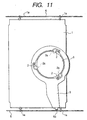
- the fixed end portion of the clamper holder 2 is fixed to a lever 9 shown in Fig. 11.
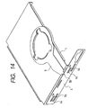
- the lever 9 is rotatively fitted in the clamper holding chassis 1 and is rotated by a slider 5 as shown in Figs. 13 and 14.
- a shaft 5b mounted upright on the slider 5 is inserted in a vertical groove (not visible in Figs. 13 and 14) formed in a bent portion of the lever 9.
- a vertical groove not visible in Figs. 13 and 14
- the lever 9 is rotated in the clockwise direction as viewed from a higher position
- the lever 9 is rotated in the counter-clockwise direction as viewed from a higher position.
- Figs. 12A to 12D show a deformation of the projection 2a of the clamper holder 2.
- Figs. 12A to 12D are drawn assuming that a weight of the clamper 8 is not applied to the clamper holder 2.
- the clamper holding chassis 1 is raised in the sequential order of Figs. 12A to 12D. As shown, the projection 2a of the clamper holder 2 deforms along the motion direction of the clamper holding chassis 1.
- the bottom surface of the clamper 8 becomes higher than the bottom surface of the clamper holding chassis 1 in the unclamp state of a disc 7. It is therefore possible to form a large space between the clamper 8 and a turntable 4 and prevent the disc 7 from contacting the clamper 8 or turntable 4 and being damaged while the disc 7 is transported. Furthermore, a stroke of the clamper holding chassis 1 necessary for reserving the space becomes small so that the disc apparatus can be made compact.
- the disc clamp mechanism proposed in JP Patent Application No.9-27354 described above has a sufficient space between the turntable 4 and clamper 8 when a disc is loaded or unloaded.
- a gap A shown in Fig. 10C
- a gap B shown in Fig. 10C
- JP10-92077 discloses a disc clamp mechanism for clamping a disc which comprises:
- the invention has been made in view of the above problems. It is an object of the present invention to provide a disc clamp mechanism for a disc apparatus capable of providing a large space between a clamper and a turntable in a disc unclamp state even if the apparatus is made compact, and capable of preventing a contact between the clamper holder and clamper and between the clamper holder and disc while the disc is rotated.
- the clamper holder may be made of a plate spring.
- the contact portion of the clamper holder is moved in a direction away from the disc and in a direction away from the clamper when the disc is clamped.
- FIGs. 1 to 6 show the main part of the disc clamp mechanism of the embodiment.
- a lever 9 of the disc clamp mechanism of this embodiment is fitted in a clamper holding chassis 1, and rotated as the clamper holding chassis 1 is raised and lowered.
- the lever is not shown.
- a clamper holder 10 made of a plate spring is rotatively supported by a shaft 9a mounted upright on the lever 9.
- a pin 1c mounted upright on the clamper holding chassis 1 is inserted into a cam groove 10c of the clamper holder 10.
- the clamper holder 10 is provided with a projection 10a for raising a clamper 8 and projection parts 10b for abutting on protruding portions 1b formed on the clamper holding chassis 1.
- Figs. 1 and 2 show the state while a disc is transported between the clamper 8 and a turntable (not shown).
- the clamper holding chassis 1 is at a raised position
- the lever 9 is at a position that the lever is rotated in the clockwise direction relative to the clamper holding chassis 1. Therefore, the clamper holder 10 is at a position that the clamper holder 10 is rotated about the shaft 9a in the counter-clockwise direction, and the projection 10a enters under the clamper 8.
- the clamper holder 10 is deformed upward by the clamper holding chassis 1 so that the clamper 8 is raised high. A distance between the clamper 8 and disc 7 is therefore long.
- sliders 5 and 6 start moving so that the clamper holding chassis 1 lowers and the lever 9 together with the clamper holder 10 rotates in the counter-clockwise direction as viewed from a higher position.
- Figs. 3 and 4 show the intermediate state during rotation.
- the clamper holder 10 deformed by the clamper chassis 1 is released from a pushing force by the clamper holding chassis 1. Therefore, the clamper holder 10 takes a free state and its projection 10a moves lower than the clamper holding chassis 1 and becomes spaced apart from the clamper 8. The clamper 8 is therefore lowered to a position where the disc 7 is squeezed, and the clamp state is established.
- the lever 9 further rotates so that the clamper holder 10 rotates about the shaft 9a in the clockwise direction by a reaction between the cam groove 10c and pin 1c and its projection 10a is spaced apart from the clamper 8.
- the protruding portions 1b and 1b raise the projection parts 10b and 10b so that the projection 10a of the clamper holder 10 is mode upward moved apart from the disc 7.
- the projection of the clamper holder may be deformed upward in a free state, and it may be lowered as the lever is moved in the disc clamp state.
- the cam groove for rotating the clamper holder may be formed in the clamper holding chassis, and a pin engaging with the cam groove may be formed on the side of the clamper holder.
- the bottom surface of the clamper can be made higher than the bottom surface of the clamper holding chassis in the disc unclamp state, a distance between the clamper and turntable can be made long so that it is possible to prevent a contact of the disc with the clamper or turntable during the disc transportation and any damage to be caused by the contact.
Landscapes
- Holding Or Fastening Of Disk On Rotational Shaft (AREA)
Description
- The present invention relates to a disc drive such as a CD player, and more particularly to a disc clamp mechanism capable of thinning a disc drive.
- An example of a conventional disc clamp mechanism for a CD player is shown in Figs. 7A to 9B. As shown in Figs. 7A and 7B, a disc motor 3 is fixedly mounted on a main chassis (not shown), and a
turntable 4 is fixedly connected to a rotary shaft of the disc motor 3. Aclamper holder 2 fixed to aclamper holding chassis 1 holds acamper 8 over theturntable 4 when adisc 7 is unclamped, as shown in Fig. 7B. - A lift mechanism for the
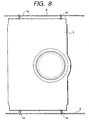
clamper holding chassis 1 is shown in Fig. 8 and Figs. 9A and 9B. Shafts 1a, 1a... mounted upright on side walls of theclamper holding chassis 1 are inserted intocam grooves sliders - The
sliders sliders clamper holding chassis 1 is raised and lowered. Theshafts - In the disc unclamp state shown in Fig. 7B, the
clamper holding chassis 1 is at a raised position. Thedisc 7 is transported by an unrepresented transport mechanism to a position over theturntable 4 via a space between theturntable 4 andclamper 8. Thereafter, as theclamper holding chassis 1 is lowered, theclamper holder 2 places theclamper 8 on theturntable 4 and becomes spaced apart from theclamper 8. - The
clamper 8 is then attracted by a magnetic force of theturntable 4 to squeeze thedisc 7 between theclamper 8 andturntable 4. This state is a clamp state of thedisc 7 as shown in Fig. 7A. Theclamped disc 7 is rotated by the disc motor 3, and an unrepresented optical pickup element is fed along a disc radial direction to reproduce data recording in thedisc 7. - Unclamping the
disc 7 is conducted by raising theclamper holding chassis 1 from the position shown in Fig. 7A. Theclamper holder 2 is made of a thin plate in order to prevent a contact with thedisc 7 andturntable 4 while thedisc 7 is clamped. - In the conventional disc clamp mechanism described above, the
clamper 8 greatly lowers toward theturntable 4 from the bottom surface of theclamper holding chassis 1 in the disc unclamp state. It is therefore difficult to provide a large space between theclamper 8 andturntable 4. From this reason, thedisc 7 may contact theclamper 8 orturntable 4 while it is transported and thedisc 7 may be damaged. - If a lift stroke of the
clamper holding chassis 1 is made large, a large space can be formed between theclamper 8 andturntable 4. However in this case, a height of the apparatus becomes large. - The applicant of this application filed JP Patent Application No.9-27354 which proposes a disc clamp mechanism for a disc apparatus capable of solving the above problems and providing a large space between a clamper and a turntable in a disc unclamp state even if the apparatus is made compact. This disc clamp mechanism for a disc apparatus is shown in Figs. 10A to 14. The operation principle of this disc clamp mechanism for a disc apparatus will be described. In Figs. 10A to 14, elements having similar functions to those of the conventional mechanism described with reference to Figs. 7A to 9B are represented by using identical reference numerals, and the detailed description thereof is omitted.
- In this example, a
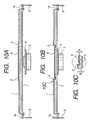
clamper holder 2 is made of a plate spring. A contact portion of theclamper holder 2 with aclamper 8 is deformed upward in a disc unclamp state. In this state, the bottom surface of theclamper 8 held by theclamper holder 2 is raised higher than the bottom surface of aclamper holding chassis 1. Fig. 10B shows a clamp state of adisc 7. - With reference to Figs. 11 to 14, the way the
clamper holder 2 is deformed will be described. Fig. 12E shows the shape of theclamper holder 2. Theclamper holder 2 has aprojection 2a at its distal end portion. In a natural state not applied with a force, theclamper holder 2 is bent two steps so that the surface of theprojection 2a is lower than its base end portion. - The fixed end portion of the
clamper holder 2 is fixed to alever 9 shown in Fig. 11. Thelever 9 is rotatively fitted in theclamper holding chassis 1 and is rotated by aslider 5 as shown in Figs. 13 and 14. - More specifically, a
shaft 5b mounted upright on theslider 5 is inserted in a vertical groove (not visible in Figs. 13 and 14) formed in a bent portion of thelever 9. As shown in Fig. 13, as theslider 5 makes theclamper holding chassis 1 rise, thelever 9 is rotated in the clockwise direction as viewed from a higher position, whereas as shown in Fig. 14, as theslider 5 makes theclamper holding chassis 1 lower, thelever 9 is rotated in the counter-clockwise direction as viewed from a higher position. - While the
lever 9 is rotated as theclamper holding chassis 1 is raised or lowered, a relative motion of thelever 9 andclamper holding chassis 1 deforms theprojection 2a of theclamper holder 2 fixed to thelever 9. - Figs. 12A to 12D show a deformation of the
projection 2a of theclamper holder 2. Figs. 12A to 12D are drawn assuming that a weight of theclamper 8 is not applied to theclamper holder 2. Theclamper holding chassis 1 is raised in the sequential order of Figs. 12A to 12D. As shown, theprojection 2a of theclamper holder 2 deforms along the motion direction of theclamper holding chassis 1. - Accordingly, as shown in Fig. 10A, the bottom surface of the
clamper 8 becomes higher than the bottom surface of theclamper holding chassis 1 in the unclamp state of adisc 7. It is therefore possible to form a large space between theclamper 8 and aturntable 4 and prevent thedisc 7 from contacting theclamper 8 orturntable 4 and being damaged while thedisc 7 is transported. Furthermore, a stroke of theclamper holding chassis 1 necessary for reserving the space becomes small so that the disc apparatus can be made compact. - The disc clamp mechanism proposed in JP Patent Application No.9-27354 described above has a sufficient space between the
turntable 4 andclamper 8 when a disc is loaded or unloaded. However, as shown in Figs. 10B and 10C, since theclamper holder 2 is positioned between theclamper 8 anddisc 7 in the disc clamp state, a gap A (shown in Fig. 10C) between theclamper holder 2 andclamper 8 and a gap B (shown in Fig. 10C) between theclamper holder 2 anddisc 7 are difficult to be made sufficient during the disc rotation. - Therefore, abnormal friction sounds between the
clamper holder 2 andclamper 8 or disc damages to be caused by a contact between theclamper holder 2 anddisc 7 may occur depending upon variations in sizes of components, variations in thicknesses of discs, rotation plane fluctuations and the like. - Document D3=JP10-92077 discloses a disc clamp mechanism for clamping a disc which comprises:
- a clamper to be coupled to a disc;
- a clamper holder capable of holding said clamper with a clamper contact portion;
- a movable member which is coupled to said clamper holder and which can move horizontally near to or away from a turntable while holding said clamper;
- the clamper contact portion can move in the motion direction of said movable member near to or away from a rotation center axis of said clamper, the clamper contact portion is adapted be in a position apart from said clamper and/or disc such that is does not come in contact with said clamper and/or disc, when said disc is clamped.
- The invention has been made in view of the above problems. It is an object of the present invention to provide a disc clamp mechanism for a disc apparatus capable of providing a large space between a clamper and a turntable in a disc unclamp state even if the apparatus is made compact, and capable of preventing a contact between the clamper holder and clamper and between the clamper holder and disc while the disc is rotated.
- In the disc clamp mechanism for a disc apparatus, the clamper holder may be made of a plate spring.
- In the disc clamp mechanism for a disc apparatus, the contact portion of the clamper holder is moved in a direction away from the disc and in a direction away from the clamper when the disc is clamped.
-
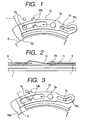
- Fig. 1 is a plan view showing the main part of a disc clamp mechanism for a CD player, with partial components being seen through, according an embodiment of the invention.
- Fig. 2 is a side view of the disc clamp mechanism shown in Fig. 1, with partial components being seen through.
- Fig. 3 is a plan view showing the main part of the disc clamp mechanism in another state, with a partial components being seen through.
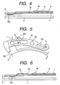
- Fig. 4 is a side view of the disc clamp mechanism shown in Fig. 3, with partial components being seen through.
- Fig. 5 is a plan view showing the main part of the disc clamp mechanism in another state, with a partial components being seen through.
- Fig. 6 is a side view of the disc clamp mechanism shown in Fig. 5, with partial components being seen through.
- Figs. 7A and 7B are front views showing an outline of the structure of a conventional disc clamp mechanism for a CD player.
- Fig. 8 is a plan view of the disc clamp mechanism shown in Figs. 7A and 7B.
- Figs. 9A and 9B are side views illustrating the operation of the disc clamp mechanism shown in Figs. 7A and 7B.
- Figs. 10A to 10C are front views showing an outline of the structure of another conventional disc clamp mechanism for a CV player, Fig. 10 showing a disc unclamp state, Fig. 10B showing a disc clamp state and Fig. 10C showing the details of a C portion in Fig. 10B.
- Fig. 11 is a plan view of the disc clamp mechanism shown in Figs. 10A to 10C.
- Figs. 12A to 12D are partial side views illustrating the operation of the disc clamp mechanism, and Fig. 12E is a plan view showing a clamper holder of the disc clamp mechanism.
- Fig. 13 is a perspective view of the disc clamp mechanism.
- Fig. 14 is a perspective view showing another state of the disc clamp mechanism.
- A disc clamp mechanism for a CD player according to an embodiment of the invention will be described with reference to the accompanying drawings. Figs. 1 to 6 show the main part of the disc clamp mechanism of the embodiment. As the conventional disc clamp mechanism, a
lever 9 of the disc clamp mechanism of this embodiment is fitted in aclamper holding chassis 1, and rotated as theclamper holding chassis 1 is raised and lowered. In Figs. 1, 3 and 5, the lever is not shown. - A
clamper holder 10 made of a plate spring is rotatively supported by ashaft 9a mounted upright on thelever 9. Apin 1c mounted upright on theclamper holding chassis 1 is inserted into acam groove 10c of theclamper holder 10. As thelever 9 is moved relative to theclamper holding chassis 1, theclamper holder 10 rotates about theshaft 9a. Theclamper holder 10 is provided with aprojection 10a for raising aclamper 8 andprojection parts 10b for abutting on protrudingportions 1b formed on theclamper holding chassis 1. - Figs. 1 and 2 show the state while a disc is transported between the
clamper 8 and a turntable (not shown). In this state, theclamper holding chassis 1 is at a raised position, and thelever 9 is at a position that the lever is rotated in the clockwise direction relative to theclamper holding chassis 1. Therefore, theclamper holder 10 is at a position that theclamper holder 10 is rotated about theshaft 9a in the counter-clockwise direction, and theprojection 10a enters under theclamper 8. Theclamper holder 10 is deformed upward by theclamper holding chassis 1 so that theclamper 8 is raised high. A distance between theclamper 8 anddisc 7 is therefore long. - As the
disc 7 is transported to a predetermined position above the turntable (not shown, refer to conventional mechanisms),sliders 5 and 6 (not shown, refer to conventional mechanisms) start moving so that theclamper holding chassis 1 lowers and thelever 9 together with theclamper holder 10 rotates in the counter-clockwise direction as viewed from a higher position. - Figs. 3 and 4 show the intermediate state during rotation. The
clamper holder 10 deformed by theclamper chassis 1 is released from a pushing force by theclamper holding chassis 1. Therefore, theclamper holder 10 takes a free state and itsprojection 10a moves lower than theclamper holding chassis 1 and becomes spaced apart from theclamper 8. Theclamper 8 is therefore lowered to a position where thedisc 7 is squeezed, and the clamp state is established. - The
lever 9 further rotates so that theclamper holder 10 rotates about theshaft 9a in the clockwise direction by a reaction between thecam groove 10c and pin 1c and itsprojection 10a is spaced apart from theclamper 8. The protrudingportions projection parts projection 10a of theclamper holder 10 is mode upward moved apart from thedisc 7. - This state is shown in Figs. 5 and 6. In this state, the
disc 7 is rotated. As shown in Fig. 5, theprojection 10a of theclamper holder 10 is spaced apart from theclamper 8 in a radial direction, and as shown in Fig. 6, the projection is spaced by a long distance D from thedisc 7. It is therefore possible to prevent a contact between thedisc 7 andclamper holder 10 and between theclamper 8 andclamper holder 10. Unclamping the disc is performed by the reversed operations described above. - The invention is not limited only to the embodiment described above. For example, the projection of the clamper holder may be deformed upward in a free state, and it may be lowered as the lever is moved in the disc clamp state.
- The cam groove for rotating the clamper holder may be formed in the clamper holding chassis, and a pin engaging with the cam groove may be formed on the side of the clamper holder.
- According to the disc clamp mechanism for a disc apparatus of this invention, since the bottom surface of the clamper can be made higher than the bottom surface of the clamper holding chassis in the disc unclamp state, a distance between the clamper and turntable can be made long so that it is possible to prevent a contact of the disc with the clamper or turntable during the disc transportation and any damage to be caused by the contact.
- Furthermore, even during the disc rotation, it is possible to reliably prevent a contact between the clamper holder and clamper and between the clamper holder and disc, because a distance between the clamper holder and disc can be maintained sufficiently long.
Claims (7)
- A disc clamp mechanism for clamping a disc (7) on a turntable (4) on which said disc is placed, said disc clamp mechanism comprising:a clamper (8) to be coupled to said disc;a clamper holder (10) capable of holding said clamper;a movable member (1) that can move in a motion direction vertical with respect to said turntable, near to or away from said turntable while holding said clamper, wherein said clamper holder (10) is movably coupled to said movable member (1); anda clamper contact portion (10a) coming in contact with said clamper, said clamper contact portion being a flexible portion of said clamper holder, wherein said clamper contact portion can move in said motion direction of said movable member and in a direction horizontal with respect to said turntable near to or away from a rotation center axis of said clamper, and wherein said clamper contact portion is adapted to be apart from said clamper and/or disc such that it does not come in contact with said clamper and/or disc, when said disc is clamped.
- The disc clamp mechanism for a disc apparatus according to claim 1, wherein:when the disc is unclamped, said clamper contact portion (10a) moves toward said clamper (8) in order to hold the clamp.
- The disc clamp mechanism for a disc apparatus according to claim 1, wherein:when a disc is clamped, said clamper contact portion (10a) moves in a direction away from the rotation center axis of said clamper after or simultaneously when the movable member is moved near to said turntable; andsaid clamper contact portion (10a) moves in a direction away from said turntable after or simultaneously when the clamper contact portion moves in the direction away from the rotation center axis of said clamper.
- The disc clamp mechanism for a disc apparatus according to claim 1, wherein when a disc is unclamped, after or simultaneously when said clamper contact portion (10a) moves in a direction near to a rotation center axis of said clamper(8), said movable member moves in a direction away from the turntable.
- The disc clamp mechanism for a disc apparatus according to claim 1, wherein:when a disc (7) is clamped, said movable member (1) and said clamper holder (10) are at positions where said movable member and said clamper holder are near to the turntable and said clamper contact portion is away from the clamper; andwhen a disc (7) is unclamped, said movable member (1) and said clamper holder (10) are at positions where said movable member and said clamper holder are away from said turntable and said clamper contact portion is near to said clamper.
- The disc clamp mechanism for a disc apparatus according to claim 1, wherein said clamper holder is made of a plate spring.
- The disc clamp mechanism for a disc apparatus according to claim 1, wherein said clamper contact portion (10a) is a protrusion extending toward the rotation center axis of the clamper.
Applications Claiming Priority (3)
| Application Number | Priority Date | Filing Date | Title |
|---|---|---|---|
| JP33672198A JP3713154B2 (en) | 1998-11-27 | 1998-11-27 | Disk clamp mechanism of disk device |
| JP33672198 | 1998-11-27 | ||
| PCT/JP1999/005550 WO2000033304A1 (en) | 1998-11-27 | 1999-10-07 | Disk clamp mechanism of disk device |
Publications (3)
| Publication Number | Publication Date |
|---|---|
| EP1052636A1 EP1052636A1 (en) | 2000-11-15 |
| EP1052636A4 EP1052636A4 (en) | 2004-06-09 |
| EP1052636B1 true EP1052636B1 (en) | 2006-12-27 |
Family
ID=18302112
Family Applications (1)
| Application Number | Title | Priority Date | Filing Date |
|---|---|---|---|
| EP99973157A Expired - Lifetime EP1052636B1 (en) | 1998-11-27 | 1999-10-07 | Disk clamp mechanism of disk device |
Country Status (10)
| Country | Link |
|---|---|
| US (1) | US6535476B1 (en) |
| EP (1) | EP1052636B1 (en) |
| JP (1) | JP3713154B2 (en) |
| KR (1) | KR100383109B1 (en) |
| CN (1) | CN1139927C (en) |
| DE (2) | DE69934576T2 (en) |
| ID (1) | ID25450A (en) |
| MY (1) | MY122196A (en) |
| TW (1) | TW519621B (en) |
| WO (1) | WO2000033304A1 (en) |
Families Citing this family (9)
| Publication number | Priority date | Publication date | Assignee | Title |
|---|---|---|---|---|
| US6721263B1 (en) * | 1999-08-20 | 2004-04-13 | Matsushita Electric Industrial Co., Ltd. | Disk holding mechanism and disk holding mechanism clamper |
| JP3704479B2 (en) * | 2001-03-23 | 2005-10-12 | 株式会社ケンウッド | Disc clamp device |
| TW505296U (en) * | 2001-10-12 | 2002-10-01 | Lite On It Corp | Reed type clamping device |
| JP3958233B2 (en) * | 2003-03-06 | 2007-08-15 | 三菱電機株式会社 | Disk unit |
| TW572322U (en) * | 2003-04-02 | 2004-01-11 | Lite On It Corp | Disk fixing device for optical disk drive |
| TWM331729U (en) * | 2007-09-17 | 2008-05-01 | Topray Technologies Inc | Large and small disk holding device |
| US8289651B2 (en) * | 2007-11-16 | 2012-10-16 | Texas Instruments Incorporated | Apparatus to control heat dissipation in hard-disk drives |
| US8082557B2 (en) * | 2009-08-03 | 2011-12-20 | Teac Corporation | Disk device |
| US8099746B2 (en) * | 2009-08-21 | 2012-01-17 | Nidec Corporation | Motor, storage disk drive apparatus and motor manufacturing method |
Family Cites Families (11)
| Publication number | Priority date | Publication date | Assignee | Title |
|---|---|---|---|---|
| JPS62125568A (en) * | 1985-11-27 | 1987-06-06 | Sansui Electric Co | Disk driving device |
| JPH0544918Y2 (en) * | 1987-06-30 | 1993-11-16 | ||
| JPH03137858A (en) * | 1989-10-24 | 1991-06-12 | Matsushita Electric Ind Co Ltd | Disk clamping device |
| JPH082838Y2 (en) * | 1990-06-06 | 1996-01-29 | 富士通テン株式会社 | Clamp mechanism |
| JPH0652615A (en) * | 1992-07-31 | 1994-02-25 | Toshiba Corp | Optical disk device |
| US5784351A (en) * | 1995-04-19 | 1998-07-21 | Sony Corporation | Loading apparatus for disk cartridge |
| JP3042769B2 (en) * | 1996-09-11 | 2000-05-22 | タナシン電機株式会社 | Disc playback device |
| JPH10312628A (en) * | 1997-05-12 | 1998-11-24 | Hitachi Ltd | Optical disk drive |
| JP3011910B2 (en) * | 1997-09-19 | 2000-02-21 | 株式会社ケンウッド | Disk clamp mechanism of disk drive |
| JP3021442B2 (en) * | 1997-12-31 | 2000-03-15 | 三星電子株式会社 | Disc player |
| KR100252128B1 (en) * | 1997-12-31 | 2000-04-15 | 윤종용 | Disk clamping apparatus for disk player |
-
1998
- 1998-11-27 JP JP33672198A patent/JP3713154B2/en not_active Expired - Lifetime
-
1999
- 1999-10-04 TW TW088117077A patent/TW519621B/en not_active IP Right Cessation
- 1999-10-07 ID IDW20001436A patent/ID25450A/en unknown
- 1999-10-07 DE DE69934576T patent/DE69934576T2/en not_active Expired - Lifetime
- 1999-10-07 CN CNB998024031A patent/CN1139927C/en not_active Expired - Lifetime
- 1999-10-07 DE DE1052636T patent/DE1052636T1/en active Pending
- 1999-10-07 KR KR10-2000-7007750A patent/KR100383109B1/en not_active Expired - Lifetime
- 1999-10-07 WO PCT/JP1999/005550 patent/WO2000033304A1/en not_active Ceased
- 1999-10-07 EP EP99973157A patent/EP1052636B1/en not_active Expired - Lifetime
- 1999-10-07 US US09/582,231 patent/US6535476B1/en not_active Expired - Lifetime
- 1999-11-24 MY MYPI99005118A patent/MY122196A/en unknown
Also Published As
| Publication number | Publication date |
|---|---|
| DE1052636T1 (en) | 2001-05-03 |
| DE69934576T2 (en) | 2007-05-03 |
| KR20010034135A (en) | 2001-04-25 |
| MY122196A (en) | 2006-03-31 |
| CN1139927C (en) | 2004-02-25 |
| US6535476B1 (en) | 2003-03-18 |
| KR100383109B1 (en) | 2003-05-12 |
| JP3713154B2 (en) | 2005-11-02 |
| WO2000033304A1 (en) | 2000-06-08 |
| EP1052636A1 (en) | 2000-11-15 |
| TW519621B (en) | 2003-02-01 |
| HK1033709A1 (en) | 2001-09-14 |
| CN1289438A (en) | 2001-03-28 |
| JP2000163839A (en) | 2000-06-16 |
| EP1052636A4 (en) | 2004-06-09 |
| ID25450A (en) | 2000-10-05 |
| DE69934576D1 (en) | 2007-02-08 |
Similar Documents
| Publication | Publication Date | Title |
|---|---|---|
| US6754903B2 (en) | Disc device | |
| US6535476B1 (en) | Disc clamp mechanism for disc apparatus | |
| US6714507B2 (en) | Disc device | |
| US6438095B1 (en) | Disc clamp mechanism for disc apparatus | |
| US6697321B2 (en) | Disc apparatus | |
| KR100816233B1 (en) | Disc clamp device | |
| WO1999008274A2 (en) | Disc loading mechanism of disc apparatus | |
| JP2002352497A (en) | Disk unit | |
| CN100498947C (en) | disk device | |
| JP3356086B2 (en) | Disc clamping device | |
| CN101211621A (en) | Optical disc device and base used in the optical disc device | |
| JP4297237B2 (en) | Disc clamp mechanism | |
| CN100433155C (en) | CD device | |
| JP2006260719A (en) | Optical disk device | |
| JPH10312628A (en) | Optical disk drive | |
| JPH0538435Y2 (en) | ||
| JP3021924B2 (en) | Disk drive device | |
| US20060031863A1 (en) | Disk chucking apparatus for small-sized disk player | |
| JPH10199083A (en) | Disc clamp device | |
| JPH02260278A (en) | Disk reproducing device | |
| HK1033709B (en) | Disk clamp mechanism of disk device | |
| JP2003123375A (en) | Disk rotation mechanism and disk device using the same | |
| JP2001236707A (en) | Disk clamp mechanism of disk drive | |
| CN101017682A (en) | Optical disc apparatus | |
| JPH11185341A (en) | Optical disk drive |
Legal Events
| Date | Code | Title | Description |
|---|---|---|---|
| PUAI | Public reference made under article 153(3) epc to a published international application that has entered the european phase |
Free format text: ORIGINAL CODE: 0009012 |
|
| 17P | Request for examination filed |
Effective date: 20000711 |
|
| AK | Designated contracting states |
Kind code of ref document: A1 Designated state(s): AT BE CH CY DE DK ES FI FR GB GR IE IT LI LU MC NL PT SE |
|
| EL | Fr: translation of claims filed | ||
| DET | De: translation of patent claims | ||
| RBV | Designated contracting states (corrected) |
Designated state(s): DE FR GB IT |
|
| A4 | Supplementary search report drawn up and despatched |
Effective date: 20040422 |
|
| 17Q | First examination report despatched |
Effective date: 20050202 |
|
| GRAP | Despatch of communication of intention to grant a patent |
Free format text: ORIGINAL CODE: EPIDOSNIGR1 |
|
| GRAS | Grant fee paid |
Free format text: ORIGINAL CODE: EPIDOSNIGR3 |
|
| GRAA | (expected) grant |
Free format text: ORIGINAL CODE: 0009210 |
|
| AK | Designated contracting states |
Kind code of ref document: B1 Designated state(s): DE FR GB IT |
|
| REG | Reference to a national code |
Ref country code: GB Ref legal event code: FG4D |
|
| RIN1 | Information on inventor provided before grant (corrected) |
Inventor name: HAGA, YOSUKE |
|
| RIN2 | Information on inventor provided after grant (corrected) |
Inventor name: HAGA, YOSUKE |
|
| REF | Corresponds to: |
Ref document number: 69934576 Country of ref document: DE Date of ref document: 20070208 Kind code of ref document: P |
|
| ET | Fr: translation filed | ||
| PLBE | No opposition filed within time limit |
Free format text: ORIGINAL CODE: 0009261 |
|
| STAA | Information on the status of an ep patent application or granted ep patent |
Free format text: STATUS: NO OPPOSITION FILED WITHIN TIME LIMIT |
|
| 26N | No opposition filed |
Effective date: 20070928 |
|
| REG | Reference to a national code |
Ref country code: DE Ref legal event code: R082 Ref document number: 69934576 Country of ref document: DE Representative=s name: LEINWEBER & ZIMMERMANN, DE |
|
| REG | Reference to a national code |
Ref country code: DE Ref legal event code: R082 Ref document number: 69934576 Country of ref document: DE Representative=s name: LEINWEBER & ZIMMERMANN, DE Effective date: 20120430 Ref country code: DE Ref legal event code: R081 Ref document number: 69934576 Country of ref document: DE Owner name: JVC KENWOOD CORPORATION, YOKOHAMA-SHI, JP Free format text: FORMER OWNER: KABUSHIKI KAISHA KENWOOD, TOKIO/TOKYO, JP Effective date: 20120430 |
|
| REG | Reference to a national code |
Ref country code: FR Ref legal event code: TP Owner name: JVC KENWOOD CORPORATION, JP Effective date: 20120705 |
|
| PG25 | Lapsed in a contracting state [announced via postgrant information from national office to epo] |
Ref country code: IT Free format text: LAPSE BECAUSE OF NON-PAYMENT OF DUE FEES Effective date: 20151007 |
|
| REG | Reference to a national code |
Ref country code: FR Ref legal event code: PLFP Year of fee payment: 18 |
|
| PG25 | Lapsed in a contracting state [announced via postgrant information from national office to epo] |
Ref country code: IT Free format text: LAPSE BECAUSE OF NON-PAYMENT OF DUE FEES Effective date: 20151007 |
|
| PGRI | Patent reinstated in contracting state [announced from national office to epo] |
Ref country code: IT Effective date: 20170616 |
|
| REG | Reference to a national code |
Ref country code: FR Ref legal event code: PLFP Year of fee payment: 19 |
|
| REG | Reference to a national code |
Ref country code: FR Ref legal event code: PLFP Year of fee payment: 20 |
|
| PGFP | Annual fee paid to national office [announced via postgrant information from national office to epo] |
Ref country code: FR Payment date: 20180913 Year of fee payment: 20 |
|
| PGFP | Annual fee paid to national office [announced via postgrant information from national office to epo] |
Ref country code: DE Payment date: 20180925 Year of fee payment: 20 |
|
| PGFP | Annual fee paid to national office [announced via postgrant information from national office to epo] |
Ref country code: IT Payment date: 20181018 Year of fee payment: 20 Ref country code: GB Payment date: 20181003 Year of fee payment: 20 |
|
| REG | Reference to a national code |
Ref country code: DE Ref legal event code: R071 Ref document number: 69934576 Country of ref document: DE |
|
| REG | Reference to a national code |
Ref country code: GB Ref legal event code: PE20 Expiry date: 20191006 |
|
| PG25 | Lapsed in a contracting state [announced via postgrant information from national office to epo] |
Ref country code: GB Free format text: LAPSE BECAUSE OF EXPIRATION OF PROTECTION Effective date: 20191006 |