CN1139927C - Disk clamp mechanism of disk device - Google Patents
Disk clamp mechanism of disk device Download PDFInfo
- Publication number
- CN1139927C CN1139927C CNB998024031A CN99802403A CN1139927C CN 1139927 C CN1139927 C CN 1139927C CN B998024031 A CNB998024031 A CN B998024031A CN 99802403 A CN99802403 A CN 99802403A CN 1139927 C CN1139927 C CN 1139927C
- Authority
- CN
- China
- Prior art keywords
- clamper
- contact portion
- disk
- dish
- gripper seat
- Prior art date
- Legal status (The legal status is an assumption and is not a legal conclusion. Google has not performed a legal analysis and makes no representation as to the accuracy of the status listed.)
- Expired - Lifetime
Links
Images


Classifications
-
- G—PHYSICS
- G11—INFORMATION STORAGE
- G11B—INFORMATION STORAGE BASED ON RELATIVE MOVEMENT BETWEEN RECORD CARRIER AND TRANSDUCER
- G11B17/00—Guiding record carriers not specifically of filamentary or web form, or of supports therefor
- G11B17/02—Details
- G11B17/022—Positioning or locking of single discs
- G11B17/028—Positioning or locking of single discs of discs rotating during transducing operation
- G11B17/0284—Positioning or locking of single discs of discs rotating during transducing operation by clampers
- G11B17/0285—Positioning or locking of single discs of discs rotating during transducing operation by clampers mounted on a bridge
Abstract
A contact between a clamper holder and clamper and between the clamper holder and disc can be reliably prevented while the disc is rotated. A disc clamp mechanism for a disc apparatus for clamping or unclamping a disc by moving a clamper holding chassis near to or remote from a turntable, the clamper holding chassis holding a clamper with a clamper holder, wherein: a lever is rotatively supported by the clamper holding chassis and moved in cooperation with a motion of the clamper holding chassis; and a contact portion of the clamper holder with the clamper is displaced in a motion direction of the clamper holding chassis and a clamper radial direction relative to the clamper holding chassis, in cooperation with a motion of the lever relative to the clamper holding chassis.
Description
The present invention relates to the disk drive of a kind of CD player and so on, more particularly, relate to a kind of clamp mechanism of disk that can the attenuate disk drive.
Fig. 7 A to 9B shows the example of an existing CD player clamp mechanism of disk.As shown in Figure 7A and 7B, a coil motor 3 is fixedly mounted on the master priming (not shown), and universal stage 4 is fixedly connected to the turning axle of coil motor 3.Shown in Fig. 7 B, when clamping disk 7 not, the gripper seat 2 that is fixed in clamper fixed mount 1 is supported on clamper 8 top of universal stage 4.
The hoisting gear of clamper fixed mount 1 has been shown among Fig. 8 and Fig. 9 A and the 9B.Be vertically mounted on the axle 1a on clamper fixed mount 1 sidewall, 1a ... be inserted in the cam path 5a of sliding part 5 and 6,5a ... in.
Unshowned drive mechanism sliding part 5 and 6 moves forward and backward with respect to master priming.With the motion of sliding part 5 and 6, clamper fixed mount 1 raises and reduces. Axle 1a, 1a ... also be inserted in the vertical channel (not shown) of master priming.
In the clamp position not of the dish shown in Fig. 7 B, clamper fixed mount 1 is in the position of a rising.A unshowned conveying mechanism is transported to dish 7 position of universal stage 4 tops through the space between universal stage 4 and the clamper 8.After this, when clamper fixed mount 1 reduced, gripper seat 2 was placed on clamper 8 on the universal stage 4, and separates with clamper 8.
Then, the magnetic attraction clamper 8 of universal stage 4 is squeezed in dish 7 between clamper 8 and the universal stage 4.This state is the dish clamp position shown in Fig. 7 A.7, one unshowned optical head elements of dish of coil motor 3 rotation clampings are radially sent into along dish, the data of playback of recorded on dish 7.
By clamper fixed mount 1 is raise from position shown in Fig. 7 A, decontrol clamping to coiling 7.Gripper seat 2 is by the thin plate manufacturing, so that coil 7 when being held, prevents and coils 7 and contact with universal stage 4.
In above-mentioned existing clamp mechanism of disk, in coiling not clamp position, clamper 8 reduces a very big segment distance from the bottom surface of clamper fixed mount 1 to universal stage 4.Therefore, be difficult to provide a big space between clamper 8 and the universal stage 4.For this reason, it may contact with clamper 8 or universal stage 4 when transfer dish 7, and may damage dish 7.
If make the lift stroke that grips frame 1 very big, can between clamper 8 and universal stage 4, form big space so.But in this case, it is big that height of devices becomes.
The application's applicant has applied for the 9-27354 Japanese patent application, this patented claim has proposed a kind of clamp mechanism of disk of the dish device that can address the above problem, even and when handle assembly is made very compactly, also can between clamper and universal stage, provide big space under the clamp position not coiling.The clamp mechanism of disk of this dish device has been shown among Figure 10 A to 14.The principle of operation of this clamping device of following explanation dish device.In Figure 10 A to 14, the element that has identical function with element with reference to the existing mechanism of figure 7A to 9B explanation represents with identical reference number, and omitted the detailed description to them.
In this example, gripper seat 2 is made by the sheet spring.In coiling not clamp position, the contact portion that gripper seat 2 contacts with clamper 8 is distortion upwards.In this state, the lower surface of the clamper 8 of gripper seat 2 supports is enhanced the position that is higher than clamper fixed mount 1 lower surface.Figure 10 B shows the clamp position of dish 7.
With reference to figures 11 to 14, the mode that makes gripper seat 2 distortion is described.Figure 12 E shows the shape of gripper seat 2.Gripper seat 2 has an outshot 2a in its end portion.Under the state of nature that does not apply power, gripper seat 2 is bent to two sections, thereby makes the surface of outshot 2a be lower than its cardinal extremity part.
The fixed end part of gripper seat 2 is fixed in a control lever 9 shown in Figure 11.Control lever 9 is engaged in the clamper fixed mount 1 rotationally, and as shown in Figure 13 and 14, is rotated by sliding part 5.
More particularly, the axle 5b that is vertically mounted on the sliding part 5 is inserted in the vertical channel (invisible in Figure 13 and 14) that is formed in control lever 9 sweeps.As shown in Figure 13, when sliding part 5 raises clamper fixed mount 1, the clockwise direction rotation of control lever 9 to see from eminence, and as shown in Figure 14, when sliding part 5 reduces clamper fixed mount 1, the counter clockwise direction rotation of control lever 9 to see from eminence.
When control lever 9 rotated with the rising of clamper fixed mount 1 or reduction, control lever 9 and the relative motion of clamper fixed mount 1 made the outshot 2a distortion of the gripper seat 2 that is fixed in control lever 9.
Figure 12 A to 12D shows the distortion of the outshot 2a of gripper seat 2.Figure 12 A to 12D is the synoptic diagram of weight when not being applied on the gripper seat 2 of hypothesis clamper 8.Clamper fixed mount 1 raises to the sequential order of 12D with Figure 12 A.As shown in the figure, the outshot 2a of gripper seat 2 is along the direction of motion distortion of clamper fixed mount 1.
Therefore, as shown in Figure 10 A, in the not clamp position of dish 7, the lower surface of clamper 8 is higher than the lower surface of clamper fixed mount 1.Thereby can between clamper 8 and universal stage 4, form big space, and prevented that dish 7 and clamper 8 or universal stage 4 from contacting and coiling 7 and being damaged when carrying.In addition, keep the stroke of the required clamper fixed mount 1 in space to diminish, thereby can make the dish device compactlyer.
When the loading or unloading dish, the clamp mechanism of disk that proposes in the above-mentioned 9-27354 Japanese patent application has enough spaces between universal stage 4 and clamper 8.But, as shown in Figure 10 B and 10C, in the dish clamp position, because gripper seat 2 is positioned at clamper 8 and coils position between 7, during disc spins, be difficult to make gap A (shown in Figure 10 C) and the gap B between gripper seat 2 and the dish 7 between gripper seat 2 and the clamper 8 enough big.
Therefore, may be owing to the variation of size of components, disc thickness changes, Plane of rotation fluctuatings etc. produce the abnormal friction sound between gripper seat 2 and the clamper 8, or gripper seat 2 with coil between 7 to contact the adjustment debit that causes bad.
Made the present invention at the problems referred to above.The objective of the invention is to provide a kind of clamp mechanism of disk that coils device, even described clamping device also can provide big space between clamper and universal stage when coiling not clamping when device is made very compactly, and can when disc spins, preventing between gripper seat and the clamper, and contacting between gripper seat and the dish.
According to an aspect of the present invention, provide a kind of by mobile clamper fixed mount near or away from the universal stage clamping or discharge the clamp mechanism of disk of the dish device of clamping disk, described clamper fixed mount supports clamper with a gripper seat, wherein: a control lever is held the device fixed mount and rotatably supports, and the motion of collaborative clamper fixed mount and moving; And the contact portion that gripper seat contacts with clamper along the direction of motion of clamper fixed mount and with respect to the clamper of clamper fixed mount radially, and the Collaborative Control bar is with respect to the motion of clamper fixed mount and move.
In the clamp mechanism of disk of dish device, gripper seat is made with the sheet spring.
In the clamp mechanism of disk of dish device, the contact portion of gripper seat is moved along the direction of leaving dish and the direction of leaving clamper when dish is held.
Fig. 1 is the planimetric map that the permeation parts assembly of major part of the clamp mechanism of disk of a CD Player according to an embodiment of the invention is seen;
Fig. 2 is the side view that the permeation parts assembly of clamp mechanism of disk shown in Figure 1 is seen;
Fig. 3 is the planimetric map that the permeation parts assembly of the major part of the clamp mechanism of disk in the another kind of state of demonstration is seen;
Fig. 4 is the side view that the permeation parts assembly of shown in Figure 3 clamp mechanism of disk is seen;
Fig. 5 is the planimetric map that the permeation parts assembly of the major part of the clamp mechanism of disk in the another kind of state of demonstration is seen;
Fig. 6 is the side view that the permeation parts assembly of the clamp mechanism of disk shown in Fig. 5 is seen;
Fig. 7 A and 7B are the front elevations of structure in general of the existing clamp mechanism of disk of a CD Player;
Fig. 8 is the planimetric map of clamp mechanism of disk shown in Fig. 7 A and the 7B;
Fig. 9 A and 9B are the side views of the operation of clamp mechanism of disk shown in key diagram 7A and the 7B;
Figure 10 A to 10C is the front elevation of structure in general that shows the clamp mechanism of disk of another kind of existing CD Player, and Figure 10 A shows the not clamp position of dish, and Figure 10 B shows the clamp position of dish and the details that Figure 10 C shows C part among Figure 10 B;
Figure 11 is the planimetric map of clamp mechanism of disk shown in Figure 10 A to 10C;
Figure 12 A to 12D is the partial side view of the operation of explanation clamp mechanism of disk, and Figure 12 E is the planimetric map of the gripper seat of display panel clamping device;
Figure 13 is the skeleton view of clamp mechanism of disk;
Figure 14 is the skeleton view of the another kind of state of clamp mechanism of disk.
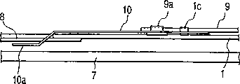
Describe below with reference to the clamp mechanism of disk of accompanying drawing CD Player according to an embodiment of the invention.Fig. 1 to 6 shows the major part of the clamp mechanism of disk of embodiment.As existing clamp mechanism of disk, a control lever 9 of the clamp mechanism of disk of present embodiment is engaged in the clamper fixed mount 1, and rotates with the lifting and the reduction of clamper fixed mount 1.At Fig. 1, in 3 and 5, not shown control lever.
The axle 9a that is vertically mounted on the control lever 9 supports a gripper seat 10 of being made by the sheet spring rotationally.A pin 1c who is vertically mounted on the clamper fixed mount 1 is inserted among the cam path 10c of gripper seat 10.When control lever 9 moved with respect to clamper fixed mount 1, gripper seat 10 rotated around axle 9a.Gripper seat 10 has one and is used to promote the outshot 10a of clamper 8 and is used to abut against on the clamper fixed mount 1 outshot 10b on the boss 1b that forms.
State when Fig. 1 and 2 shows dish and carries between clamper 8 and universal stage (not shown).In this state, clamper fixed mount 1 is in raised position, and control lever 9 is in respect to clamper fixed mount 1 right handed position.Therefore, gripper seat 10 is in the position that counterclockwise rotates around axle 9a, and outshot 10a enters clamper 8 belows.Clamper fixed mount 1 makes upwards distortion of gripper seat 10, thereby clamper 8 is raise.Therefore, the distance between clamper 8 and the dish 7 is elongated.
To be transported to universal stage (not shown when dish 7, with reference to existing mechanism) during the precalculated position of top, sliding part 5 and 6 is (not shown, with reference to existing mechanism) setting in motion, thereby clamper fixed mount 1 is reduced, and control lever 9 and the gripper seat 10 counter clockwise direction rotation to see together from eminence.
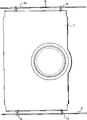
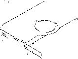
Fig. 3 and 4 shows the intermediateness in the rotary course.Clamper fixed mount 1 discharges the gripper seat 10 that is held 1 distortion of device fixed mount from thrust.Therefore, gripper seat 10 is in a kind of free state, and its outshot 10a moves to the position that is lower than clamper fixed mount 1, separates with clamper 8.Thereby make clamper 8 be reduced to dish 7 positions that are extruded, set up clamp position.
This state has been shown among Fig. 5 and 6.Dish 7 rotates in this state.As shown in Figure 5, the outshot 10a of gripper seat 10 is spaced apart with clamper 8 diametrically, and as shown in Figure 6, outshot and the distance D of coiling 7 interval one segment lengths.Therefore, can prevent to coil 7 and gripper seat 10 between, and contacting between clamper 8 and the gripper seat 10.By the opposite operation of aforesaid operations, can discharge clamping to dish.
The present invention is not limited in the foregoing description.For example, can make outshot upwards distortion under free state of gripper seat, and the motion with control lever can reduce it in the dish clamp position.
Can be formed on the cam path of swing holder bearing on the clamper fixed mount and be formed on the side of gripper seat with the pin of cam path engagement.
Clamp mechanism of disk according to dish device of the present invention, owing in clamp position not, can make the lower surface of clamper be higher than the lower surface of clamper fixed mount, thereby the distance between clamper and the universal stage of can extending, thereby can during dish is carried, prevent that dish from contacting with clamper or universal stage, and prevent to contact any damage that causes.
In addition,,, thereby can prevent reliably between gripper seat and the clamper because gripper seat can comprise sufficiently long distance with dish even during disc spins, and contacting between gripper seat and the dish.
Claims (14)
1. a clamp mechanism of disk is used for clamping disk on the universal stage of holding tray (7), and described clamp mechanism of disk comprises:
Clamper (8) is connected to described dish;
Gripper seat (10) can support described clamper;
Movable part (1) links to each other with described gripper seat, can be when supporting described clamper, near or away from the direction of motion of described universal stage on move; And
Clamper contact portion (10a), contact with described clamper, described clamper contact portion is the part of described gripper seat, wherein said clamper contact portion can on the direction of motion of described movable part and near or away from the direction of the rotary middle spindle of described clamper on move, wherein when the described dish of clamping, described clamper contact portion is used for away from described clamper and/or dish, makes described clamper contact portion not contact with described clamper and/or dish.
2. the clamp mechanism of disk of dish device according to claim 1, wherein, when the clamping decontroled dish, described clamper contact portion (10a) moves to support clamper to described clamper (8).
3. the clamp mechanism of disk of a dish device according to claim 1, wherein:
When clamping disk, described clamper contact portion (10a) is after movable part shifts near described universal stage or simultaneously along moving away from the direction of described clamper rotary middle spindle; With
Described clamper contact portion (10a) is after moving away from described clamper rotation center direction of principal axis in clamper contact portion edge or simultaneously along moving away from the direction of described universal stage.
4. the clamp mechanism of disk of a dish device according to claim 1, wherein: when the clamping decontroled dish, in described clamper contact portion (10a) after move or simultaneously, move away from the direction of described universal stage in described movable part edge near the rotation center direction of principal axis of described clamper.
5. the clamp mechanism of disk of a dish device according to claim 1, wherein:
When clamping disk (7), described movable part (1) and described gripper seat (10) are positioned at described movable part and described gripper seat near universal stage, and described clamper contact portion is away from the position of described clamper; With
When decontroling dish (7) clamping, described movable part (1) and described gripper seat (10) are in described movable part and described gripper seat away from described universal stage, and the position of the close described clamper of described clamper contact portion.
6. the clamp mechanism of disk of a dish device according to claim 1, wherein said gripper seat is made by the sheet spring.
7. the clamp mechanism of disk of a dish device according to claim 1, wherein said clamper contact portion (10a) is an outshot that stretches to the rotary middle spindle of described clamper.
One kind by clamper (8) the dish (7) be clamped in the dish device universal stage (4) on clamp mechanism of disk, comprising:
One can along near or move away from the direction of universal stage, and have one at least greater than the movable part (1) of the opening of the diameter of clamper (8) diameter;
The rotary part (9) that can rotate with respect to described movable part in the position of the opening of aiming at described movable part, described rotary part has the opening of bigger than the diameter of a clamper at least diameter; With
One is used for stretching out the gripper seat that supports clamper by the opening of described movable part
(10), described gripper seat along near or away from the rotation of the collaborative described rotary part of direction of universal stage and move,
Wherein said gripper seat have one can along near or away from the direction of the rotary middle spindle of clamper, and along near or the clamper contact portion (10a) of moving away from the direction of universal stage.
9. clamp mechanism of disk according to claim 8, wherein: when clamping disk (7), rotate with the motion of the collaborative described movable part (1) of described rotary part (9), described clamper (8) contact portion is moved along the direction near universal stage; With
After this, move away from the direction of the rotary middle spindle of clamper with away from the direction of universal stage in clamper contact portion (10a) edge, so that described gripper seat does not contact with clamper (8) and/or dish (7).
10. clamp mechanism of disk according to claim 8, wherein:
When the clamping decontroled dish, the motion rotation of the collaborative described movable part (1) of described rotary part (9) and described clamper contact portion (10a) be along the direction near universal stage, and move along the direction near the rotation center of clamper; With
After this described clamper contact portion (10a) is along the direction motion away from universal stage (4).
11. a clamp mechanism of disk according to claim 8, wherein said gripper seat is made with the sheet spring.
12. a clamp mechanism of disk according to claim 8, wherein clamper contact portion (10a) is an outshot that stretches out to the rotary middle spindle of clamper (8).
13. clamp mechanism of disk according to claim 8, wherein:
Described gripper seat (10) has the cam path (10c) of the rotary manipulation of a collaborative described rotary part
Cam path (10c) comprises arch first cam path that is parallel to the opening of described rotary part, with one with the second continuous and not parallel cam path of first cam path with opening;
Described movable part (1) has a pin (1c) that is inserted in the cam path;
Described movable part (1) has one and is used for moving the projection section (1b) of described movable part away from described gripper seat;
First cam path that rotation by described rotary part causes and the reacting force of pin, described clamper contact portion (10a) along near or move away from the direction of described movable part;
By the reacting force of second cam path and pin (1c), described clamper contact portion (10a) along near or move away from the direction of the rotary middle spindle of clamper; With
By the reacting force of projection section (1b) and described gripper seat, the clamper contact portion along near or move away from the direction of universal stage.
14. a clamp mechanism of disk according to claim 11, wherein said gripper seat (2) comprising:
First planar section (n) with a cam path;
Second planar section (1) with clamper contact portion (2a); With
One with different angles be connected in described first and second planar sections (n, the 3rd planar section (m) l),
Wherein the 3rd planar section (m) interacts with parts (p) on every side so that the clamper contact portion along near or move away from the direction of described gripper seat.
Applications Claiming Priority (2)
| Application Number | Priority Date | Filing Date | Title |
|---|---|---|---|
| JP33672198A JP3713154B2 (en) | 1998-11-27 | 1998-11-27 | Disk clamp mechanism of disk device |
| JP336721/1998 | 1998-11-27 |
Publications (2)
| Publication Number | Publication Date |
|---|---|
| CN1289438A CN1289438A (en) | 2001-03-28 |
| CN1139927C true CN1139927C (en) | 2004-02-25 |
Family
ID=18302112
Family Applications (1)
| Application Number | Title | Priority Date | Filing Date |
|---|---|---|---|
| CNB998024031A Expired - Lifetime CN1139927C (en) | 1998-11-27 | 1999-10-07 | Disk clamp mechanism of disk device |
Country Status (11)
| Country | Link |
|---|---|
| US (1) | US6535476B1 (en) |
| EP (1) | EP1052636B1 (en) |
| JP (1) | JP3713154B2 (en) |
| KR (1) | KR100383109B1 (en) |
| CN (1) | CN1139927C (en) |
| DE (2) | DE69934576T2 (en) |
| HK (1) | HK1033709A1 (en) |
| ID (1) | ID25450A (en) |
| MY (1) | MY122196A (en) |
| TW (1) | TW519621B (en) |
| WO (1) | WO2000033304A1 (en) |
Families Citing this family (9)
| Publication number | Priority date | Publication date | Assignee | Title |
|---|---|---|---|---|
| JP3848159B2 (en) * | 1999-08-20 | 2006-11-22 | 松下電器産業株式会社 | Disc holding mechanism and disc holding mechanism clamper |
| JP3704479B2 (en) * | 2001-03-23 | 2005-10-12 | 株式会社ケンウッド | Disc clamp device |
| TW505296U (en) * | 2001-10-12 | 2002-10-01 | Lite On It Corp | Reed type clamping device |
| JP3958233B2 (en) * | 2003-03-06 | 2007-08-15 | 三菱電機株式会社 | Disk unit |
| TW572322U (en) * | 2003-04-02 | 2004-01-11 | Lite On It Corp | Disk fixing device for optical disk drive |
| TWM331729U (en) * | 2007-09-17 | 2008-05-01 | Topray Technologies Inc | Large and small disk holding device |
| US8289651B2 (en) * | 2007-11-16 | 2012-10-16 | Texas Instruments Incorporated | Apparatus to control heat dissipation in hard-disk drives |
| US8082557B2 (en) * | 2009-08-03 | 2011-12-20 | Teac Corporation | Disk device |
| CN101996656B (en) * | 2009-08-21 | 2013-03-20 | 日本电产株式会社 | Motor, storage disk drive apparatus and motor manufacturing method |
Family Cites Families (11)
| Publication number | Priority date | Publication date | Assignee | Title |
|---|---|---|---|---|
| JPS62125568A (en) | 1985-11-27 | 1987-06-06 | Sansui Electric Co | Disk driving device |
| JPH0544918Y2 (en) | 1987-06-30 | 1993-11-16 | ||
| JPH03137858A (en) * | 1989-10-24 | 1991-06-12 | Matsushita Electric Ind Co Ltd | Disk clamping device |
| JPH082838Y2 (en) | 1990-06-06 | 1996-01-29 | 富士通テン株式会社 | Clamp mechanism |
| JPH0652615A (en) * | 1992-07-31 | 1994-02-25 | Toshiba Corp | Optical disk device |
| US5784351A (en) * | 1995-04-19 | 1998-07-21 | Sony Corporation | Loading apparatus for disk cartridge |
| JP3042769B2 (en) | 1996-09-11 | 2000-05-22 | タナシン電機株式会社 | Disc playback device |
| JPH10312628A (en) | 1997-05-12 | 1998-11-24 | Hitachi Ltd | Optical disk device |
| JP3011910B2 (en) | 1997-09-19 | 2000-02-21 | 株式会社ケンウッド | Disk clamp mechanism of disk drive |
| JP3021442B2 (en) | 1997-12-31 | 2000-03-15 | 三星電子株式会社 | Disc player |
| KR100252128B1 (en) | 1997-12-31 | 2000-04-15 | 윤종용 | Disk clamping apparatus for disk player |
-
1998
- 1998-11-27 JP JP33672198A patent/JP3713154B2/en not_active Expired - Lifetime
-
1999
- 1999-10-04 TW TW088117077A patent/TW519621B/en not_active IP Right Cessation
- 1999-10-07 KR KR10-2000-7007750A patent/KR100383109B1/en active IP Right Grant
- 1999-10-07 WO PCT/JP1999/005550 patent/WO2000033304A1/en active IP Right Grant
- 1999-10-07 ID IDW20001436A patent/ID25450A/en unknown
- 1999-10-07 DE DE69934576T patent/DE69934576T2/en not_active Expired - Lifetime
- 1999-10-07 US US09/582,231 patent/US6535476B1/en not_active Expired - Lifetime
- 1999-10-07 DE DE1052636T patent/DE1052636T1/en active Pending
- 1999-10-07 EP EP99973157A patent/EP1052636B1/en not_active Expired - Lifetime
- 1999-10-07 CN CNB998024031A patent/CN1139927C/en not_active Expired - Lifetime
- 1999-11-24 MY MYPI99005118A patent/MY122196A/en unknown
-
2001
- 2001-05-25 HK HK01103641A patent/HK1033709A1/en not_active IP Right Cessation
Also Published As
| Publication number | Publication date |
|---|---|
| WO2000033304A1 (en) | 2000-06-08 |
| TW519621B (en) | 2003-02-01 |
| DE69934576T2 (en) | 2007-05-03 |
| JP3713154B2 (en) | 2005-11-02 |
| HK1033709A1 (en) | 2001-09-14 |
| JP2000163839A (en) | 2000-06-16 |
| KR20010034135A (en) | 2001-04-25 |
| DE1052636T1 (en) | 2001-05-03 |
| US6535476B1 (en) | 2003-03-18 |
| CN1289438A (en) | 2001-03-28 |
| EP1052636A4 (en) | 2004-06-09 |
| ID25450A (en) | 2000-10-05 |
| EP1052636B1 (en) | 2006-12-27 |
| EP1052636A1 (en) | 2000-11-15 |
| DE69934576D1 (en) | 2007-02-08 |
| MY122196A (en) | 2006-03-31 |
| KR100383109B1 (en) | 2003-05-12 |
Similar Documents
| Publication | Publication Date | Title |
|---|---|---|
| CN1139927C (en) | Disk clamp mechanism of disk device | |
| US7739704B2 (en) | Disk apparatus having traverse and spindle cam members and method of operating same | |
| CN1122993C (en) | Disc clamp mechanism for disc apparatus | |
| JP4294616B2 (en) | Slot-in type disk unit | |
| CN1215475C (en) | Optical disc setting device for disc player | |
| US6646973B2 (en) | Disk device having disk transferring mechanism capable of shortening disk replacement time | |
| JPS63204547A (en) | Disk device | |
| JP2000132895A (en) | Movement mechanism for disk drive mechanism | |
| JP3770119B2 (en) | Optical disk device | |
| CN1867981A (en) | Disk device | |
| JPS62212964A (en) | Disk device | |
| CN1157725C (en) | Holding mechanism of disc regerating device | |
| US9966101B1 (en) | Optical disk drive with multiple optical pick-up heads | |
| KR19980071557A (en) | Disc drive | |
| JP3821595B2 (en) | Disk unit | |
| US20110099565A1 (en) | Disk Apparatus and Chucking Method Thereof | |
| JP3097878U (en) | Disk unit | |
| JPH05205384A (en) | Disk player | |
| JP3278417B2 (en) | Recording medium transport device | |
| JP2003123375A (en) | Disk rotating mechanism and disk device using the same | |
| CN1584997A (en) | Optical disk drive | |
| CN1825442A (en) | Optical disk apparatus | |
| JPH056605A (en) | Loading apparatus for optical disk | |
| JPH10222961A (en) | Disk loading mechanism of disk apparatus | |
| US20040228227A1 (en) | Disk loading device |
Legal Events
| Date | Code | Title | Description |
|---|---|---|---|
| C06 | Publication | ||
| PB01 | Publication | ||
| C10 | Entry into substantive examination | ||
| SE01 | Entry into force of request for substantive examination | ||
| C14 | Grant of patent or utility model | ||
| GR01 | Patent grant | ||
| ASS | Succession or assignment of patent right |
Owner name: JVC KENWOOD CORPORATION Free format text: FORMER OWNER: KABUSHIKI KAISHA KENWOOD;KABUSHIKI KAISHA KENWOOD Effective date: 20140227 |
|
| TR01 | Transfer of patent right | ||
| TR01 | Transfer of patent right |
Effective date of registration: 20140227 Address after: Kanagawa Patentee after: JVC Kenwood Corp. Address before: Tokyo, Japan Patentee before: Kenwood Corp. |
|
| CX01 | Expiry of patent term | ||
| CX01 | Expiry of patent term |
Granted publication date: 20040225 |