EP1052504A2 - Multi-capillary electrophoretic apparatus - Google Patents
Multi-capillary electrophoretic apparatus Download PDFInfo
- Publication number
- EP1052504A2 EP1052504A2 EP00109820A EP00109820A EP1052504A2 EP 1052504 A2 EP1052504 A2 EP 1052504A2 EP 00109820 A EP00109820 A EP 00109820A EP 00109820 A EP00109820 A EP 00109820A EP 1052504 A2 EP1052504 A2 EP 1052504A2
- Authority
- EP
- European Patent Office
- Prior art keywords
- capillary
- data
- time
- series data
- correction
- Prior art date
- Legal status (The legal status is an assumption and is not a legal conclusion. Google has not performed a legal analysis and makes no representation as to the accuracy of the status listed.)
- Withdrawn
Links
Images




Classifications
-
- G—PHYSICS
- G01—MEASURING; TESTING
- G01N—INVESTIGATING OR ANALYSING MATERIALS BY DETERMINING THEIR CHEMICAL OR PHYSICAL PROPERTIES
- G01N27/00—Investigating or analysing materials by the use of electric, electrochemical, or magnetic means
- G01N27/26—Investigating or analysing materials by the use of electric, electrochemical, or magnetic means by investigating electrochemical variables; by using electrolysis or electrophoresis
- G01N27/416—Systems
- G01N27/447—Systems using electrophoresis
- G01N27/44756—Apparatus specially adapted therefor
- G01N27/44782—Apparatus specially adapted therefor of a plurality of samples
-
- G—PHYSICS
- G01—MEASURING; TESTING
- G01N—INVESTIGATING OR ANALYSING MATERIALS BY DETERMINING THEIR CHEMICAL OR PHYSICAL PROPERTIES
- G01N27/00—Investigating or analysing materials by the use of electric, electrochemical, or magnetic means
- G01N27/26—Investigating or analysing materials by the use of electric, electrochemical, or magnetic means by investigating electrochemical variables; by using electrolysis or electrophoresis
- G01N27/416—Systems
- G01N27/447—Systems using electrophoresis
- G01N27/44704—Details; Accessories
- G01N27/44717—Arrangements for investigating the separated zones, e.g. localising zones
- G01N27/44721—Arrangements for investigating the separated zones, e.g. localising zones by optical means
Definitions
- the present invention relates to a multi-capillary electrophoretic apparatus employed for separation of protein or sequence determination for DNA.
- a multi-capillary electrophoretic apparatus comprises a multi-capillary array electrophoresis part, an optical measuring part and a data processing part.
- the multi-capillary array electrophoresis part has an arrangement of a plurality of capillary columns for injecting each of a plurality of samples into the capillary columns and simultaneously electrophoresing the same in all capillary columns.
- the optical measuring part irradiates the capillary columns with light in the multi-capillary array electrophoresis part, scans the irradiated positions perpendicularly to an electrophoresis direction, detects the intensity of light from the samples of the irradiated parts and measures scan waveforms.
- the data processing part produces time-series data as to each capillary column from the scan waveforms obtained by the optical measuring part.
- a multi-capillary electrophoretic apparatus for sequence determination for DNA employs Sanger's reaction and electrophoreses a DNA fragment sample prepared by labeling a primer or a terminator with a fluorescent material for detecting fluorescence from the DNA fragment sample in the course of electrophoresis and determining the base sequence.
- a high-speed DNA sequencer having high sensitivity and high throughput is necessary for sequence determination for DNA such as a human genome having long base sequence.
- a multi-capillary DNA sequencer having an arrangement of a plurality of capillary columns charged with gels is proposed in place of that employing flat slab gels.
- samples are not only easy to handle or inject but can also be electrophoresed at a high speed and detected in high sensitivity as compared with the slab gels. While bands are spread due to influence by Joulean heat or a temperature gradient is caused when a high voltage is applied to the slab gels, the capillary columns have no such problem and enable high-speed detection with small spreading of bands in high-speed electrophoresis with application of a high voltage.
- a detected part of a capillary array 2 having an alignment of a plurality of capillary columns is scanned perpendicularly to a direction for electrophoresing samples in the capillary columns as shown by a straight line 3 in Fig 1 for receiving fluorescence from the samples passing through the scanned position.
- the fluorescence is received at for example 13000 points, in a single scanning Each of these points is referred to as a sampling point or a data point.
- the samples which are DNA fragment samples, are labeled in four types in response to end bases adenine (A), guanine (G), thymine (T) and cytosine (C). Therefore, the base sequence can be determined by separating the received fluorescence into its spectral components thereby identifying the types of the bases passing through the scanned position.
- Scan waveforms obtained by scanning the scan line 3 on a fixed time frame are detected as peaks by electrophoresing and passing the DNA fragment samples through columns C1, C2, C3, ..., as shown in Fig. 2A. While symbols A, C, T and G denote DNA fragments of the four types of bases respectively, a common detector detects these four signals as light components of different wavelengths. Symbols t 1 , t 2 , ... denote times of scanning the scan line 3 respectively at a rate of once a second, for example.
- the DNA fragment samples pass through the position of the scan line 3 and hence the scan waveforms change with the elapse of time.
- time-series data shown in Fig 2B is obtained.
- Fig. 2B shows part of time-series data related to adenine (A) as to the column C1.
- the scan waveforms obtained by scanning the scan line 3 there may exist such signals exceeding input levels as those of adenine (A) and thymine (T) in the columns C2 and C3 in Fig. 2A.
- the input levels are determined by the detection range of the detector of the optical measuring part or the input range of an A-D converter capturing data in a data processing part.
- the peaks on the scan waveforms are saturated.
- the time-series data are distorted.
- the scan waveforms have tailing due to an electric time-constant of the detector. Therefore, in the scan waveform of a capillary column detected immediately after a capillary column allowing detection of strong fluorescence, influence by tailing of the strong signal appears with addition of signal intensity. This also results in distortion.
- positions for acquiring the time-series data from the scan waveforms are previously fixed with reference to the positions of the capillary columns.
- fluctuation of peak positions may be observed also in scan waveforms in a short time so assumed that the capillary column positions hardly fluctuate.
- the positions of the capillary columns may fluctuate with the elapse of time. Also in this case, it follows that the data are acquired on positions varied with time in the capillary columns when acquiring the time-series data from the scan waveforms on the basis of previously set capillary column position information, also resulting in distortion.
- an object of the present invention is to improve the precision of time-series data by reducing distortion caused when converting scan waveforms to time-series data.
- a multi-capillary electrophoretic apparatus comprises a multi-capillary array electrophoresis part having an arrangement of a plurality of capillary columns for injecting each of a plurality of samples into the capillary columns and simultaneously electrophoresing the samples in all capillary columns, an optical measuring part for measuring scan waveforms by irradiating the capillary columns with light in the multi-capillary array electrophoresis part, scanning irradiated positions in a direction perpendicular to a electrophoresis direction, and detecting the intensity of light from the samples of irradiated parts, and a data processing part for producing time-series data as to each capillary column from the scan waveforms obtained by the optical measuring part.
- the data processing part comprises a saturated data correction part for correcting saturated peaks included in the scan waveforms, which are saturated beyond the detection range of a detector of the optical measuring part or the input range of an A-D converter capturing data in the data processing part, to light intensity value measured on the assumption that the peaks are unsaturated in an aspect of the present invention.
- the data processing part produces the time-series data on the basis of unsaturated scan waveform peaks and the light intensity value corrected by the saturated data correction part as to the saturated scan waveform peaks.
- the data processing part preferably comprises a correction data storage part for storing correction data indicating the relationship between the number of data points of saturated parts of the saturated scan waveform peaks and light intensity data obtained on the assumption that the peaks are unsaturated.
- the saturated data correction part corrects measured light intensity value on the basis of the correction data stored in the correction data storage part as to the saturated peaks.
- the correction data storage part can store correction data indicating the relationship between the number of the data points of the saturated parts and peak heights obtained on the assumption that the peaks are unsaturated.
- the saturated data correction part can employ the peak heights stored in the correction data storage part as time-series data of the saturated scan waveform peaks.
- the correction data storage part can store correction data indicating the relationship between the number of the data points of the saturated parts and scan waveforms obtained on the assumption that the peaks are unsaturated.
- the saturated data correction part can employ the data on prescribed positions of the corrected scan waveforms of the capillary columns as time-series data of the saturated scan waveform peaks.
- the saturated data correction part obtains the light intensity value measured on the assumption that the peaks are unsaturated for producing the time-series data with the corrected light intensity value, thereby suppressing distortion of the time-series data.
- the data processing part comprises a tailing correction part for removing tailing components caused by electric time-constants of the light intensity signals of capillary columns located on front positions in the scan waveforms when producing the time-series data from the scan waveforms.
- the time-series data can be obtained on the basis of correct signal intensity by removing influence by tailing.
- the data processing part comprises a capillary position correction part for obtaining a position maximizing the light intensity signals around the previously set capillary column position for data acquisition, and acquires the time-series data on the basis of the position maximizing the light intensity signals obtained by the capillary position correction part when producing the time-series data from the scan waveforms.
- the data processing part has a function of periodically correcting the capillary column position information for data acquisition, and acquires the time-series data from the scan waveforms on the basis of the corrected capillary column position information when producing the time-series data from the scan waveforms.
- distortion of the time-series data resulting from errors in the positions for acquiring the time-series data can be prevented by correcting the positions for acquiring the time-series data from the scan waveforms.
- the multi-capillary electrophoretic apparatus may comprise any one or more than two of the saturated data correction part, the tailing correction part, the capillary position correction part having the function of obtaining the position maximizing the light intensity signal and the capillary position correction part having the function of periodically correcting the capillary column position information.
- the correction data storage part can store the correction data indicating the relationship between the number of the data points of the saturated parts and the peak heights obtained on the assumption that the peaks are unsaturated so that the saturated data correction part can employ the peak heights stored in the correction data storage part as time-series data of the saturated scan waveform peaks.
- the correction data storage part can also store correction data indicating the relationship between the number of the data points of the saturated parts and scan waveforms obtained on the assumption that the peaks are unsaturated so that the saturated data correction part can employ data on prescribed positions of corrected scan waveforms of the capillary columns as time-series data of the saturated scan waveform peaks.
- the multi-capillary electrophoretic apparatus correcting the light intensity data of the saturated peaks included in the scan waveforms, removing the tailing components or correcting the capillary position information for acquiring data can suppress distortion of the time-series data.
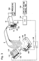
- Fig. 3 is a schematic perspective view showing an embodiment.
- a pair of reservoirs 110 and 120 store buffer solutions 112 and 122 with electrodes 130 and 132 provided therein respectively.
- a sample plate 100 made of an insulating material has a flat surface and a connector part 106 connected thereto.
- a plurality of wells 102 are vertically and horizontally arranged at regular intervals on the surface of the sample plate 100.
- Each well 102 which is a bottomed hole, is formed with an individual electrode pattern extending from the bottom to the connector part 106 through the surface of the sample plate 100. Samples are introduced into the respective wells 102 of the sample plate 100, and a high-voltage distribution cable is connected to the connector part 106.
- the reservoir 110 and the sample plate 100 are switchably connected to a high-voltage switching part 136 so that distribution is switchable.
- a high-voltage power source 134 is connected between the high-voltage switching part 136 and the electrode 132 provided in the other reservoir 120.
- An applied voltage control part 138 controlling applied voltages and times for sample introduction and electrophoresis is connected to the high-voltage power source 134.
- a microcomputer or the like implements the applied voltage control part 138.
- one ends 2a of capillary columns forming a capillary array 2 are inserted into the respective wells 102 of the sample plate 100.
- the one ends 2a of the capillary columns are dipped in the buffer solution 112 stored in the reservoir 110.
- Other ends 2b of the capillary columns forming the capillary array 2 are dipped in the buffer solution 122 stored in the reservoir 120.
- the capillary array 2 is provided with a detected part 2c on the side closer to the ends 2b, so that an optical measuring part 10 detecting the samples irradiates the detected part 2c with measuring light or excitation light for detecting absorbance by the samples or fluorescence from the samples.
- the optical measuring part 10 is connected to a data processing part 200 for converting scan waveforms obtained by the optical measuring part 10 to time-series data as to the respective capillary columns.
- the data processing part 200 comprises a time-series data production part 202 for producing the time-series data as to the respective capillary columns from the scan waveforms obtained by the optical measuring part 10.
- Symbol 204 denotes a correction data storage part storing correction data indicating the relationship between the number of data points of saturated parts and light intensity data obtained on the assumption that peaks are unsaturated as to peaks saturated beyond the detection range of a detector of the optical measuring part 10 or the input range of an A-D converter capturing data in the data processing part 200 among peaks of the scan waveforms.
- Numeral 206 denotes a saturated data correction part for obtaining light intensity data as to the saturated peaks among the peaks of the scan waveforms on the basis of the correction data stored in the correction data storage part 204.
- the time-series data production part 202 employs unsaturated scan waveform peaks as such while employing the light intensity data obtained by the saturated data correction part 206 as to saturated scan waveform peaks for producing the time-series data.
- Numeral 208 denotes a tailing correction part removing tailing components caused by electric time-constants of light intensity signals from capillary columns located on front positions of the scan waveforms when the time-series data production part 202 produces the time-series data from the scan waveforms.
- Numeral 210 denotes a capillary position correction part obtaining positions maximizing the light intensity signals around the previously set capillary column positions for data acquisition.
- the time-series data production part 202 employs data of the positions obtained by the capillary position correction part 210 as the time-series data.
- the capillary position correction part 210 can have a function of periodically correcting the capillary column position information for data acquisition.
- the time-series data production part 202 can acquire the time-series data from the scan waveforms on the basis of the corrected capillary column position information when producing the time-series data from the scan waveforms.
- the capillary position correction part 210 may attain both or one of the functions of obtaining the positions maximizing the light intensity signals and the functions of periodically correcting the capillary column position information for data acquisition.
- the data processing part 200 comprises the time-series data production part 202 as an indispensable one, and additionally comprises at least one the set of the correction data storage part 204 and the saturated data correction part 206, the tailing correction part 208 and the capillary position correction part 210.
- a broken line appearing in Fig. 4 shows connection in the case of not comprising the set made of the correction data storage part 204 and the saturated data correction part 206.
- the capillary array 2 has a two-dimensional capillary column arrangement corresponding to the arrangement of the wells 102 of the sample plate 100 on the side of the one ends 2a.
- the capillary columns are aligned on the detected part 2c and irradiated with the measuring light or the excitation light from a direction perpendicular to the arrangement planes of the capillary columns.
- the capillary columns made of quartz glass or borosilicate glass (e.g., Pyrex), are for example 200 to 300 ⁇ m in outer diameter and 75 to 100 ⁇ m in inner diameter.
- the outer peripheries of the capillary columns are preferably covered with coatings of a non-fluorescent material such as SiO 2 not fluorescing by excitation light ranging from the ultraviolet region to the near-infrared region or fluorescing to a degree not hindering fluorescence measurement.
- the coatings may not be removed on the detected part 2c.
- the capillary columns have fluorescing resin coatings, the coatings are removed on the detected part 2c.
- a plurality of such capillary columns are arranged in the capillary array 2.
- the capillary columns are charged with polyacrylamide gels, linear acrylamide gels, polyethylene oxide (PEO) gels or the like as gels of separation media.
- Samples containing four types of DNA fragments labeled with four types of fluorescent materials selected from fluorescent materials such as FAM, JOE, TAMRA, ROX, R6G and R-110 varied with end bases or labeled in four types with at least two types of fluorescent materials at different rates are injected into the capillary columns respectively and simultaneously electrophoresed.
- a moving mechanism (not shown in Fig. 3) switches and arranges the sample plate 100 and the reservoir 110 as shown by thick arrow so that either one selectively comes into contact with the one ends 2a of the capillary columns.
- the samples are introduced into the wells 102 of the sample plate 100 respectively.
- the wells 102 can also be employed to perform sample injection by inserting capillary column ends into the samples introduced into the wells 102 after treating the samples by a PCR (polymerase chain reaction) method with the wells 102.
- the PCR method is a method of remarkably amplifying only the target part of DNA.
- a primer is added to a sample of DNA and temperature is raised for dissociating double-stranded DNA to single chains. Then the temperature is lowered for bonding the primer to the DNA chains and the temperature is slightly raised for synthesizing DNA. The temperature is further raised for making single chains. The operation of lowering and raising the temperature is repeated for largely amplifying prescribed part of DNA.
- the high-voltage power source 134 applies a high voltage between the wells 102 and the buffer solution 122 for injecting the samples into the capillary columns.
- the applied voltage control part 138 controls the voltage and the time to be applied.
- the moving mechanism moves the sample plate 100 and the reservoir 110 thereby dipping the ends 2a of the capillary columns in the buffer solution 112 stored in the reservoir 110. Thereafter a high voltage is applied between the reservoirs 110 and 120 for performing separation by electrophoresis.
- a power supply voltage for electrophoresis is for example 30 kV, and a current capacity is 10 to 30 mA.
- FIG. 6A An actual scan waveform (Fig. 6A) is acquired and a waveform as to a single capillary column is assumed to be y(t), where t represents time.
- a theoretical electrophoresis waveform x(t) (Fig. 6B) is formed.
- h(t) represents a function indicating a characteristic specific to the apparatus
- h( ⁇ ) represents an impulse response
- Fig. 6C The constant of the function h( ⁇ ) can be obtained by fitting the above expression (1) to the actually acquired scan waveform.
- the waveform y(t) obtained by changing the amplitude of the theoretical waveform x(t) is simulated by the expression (1) with the function h( ⁇ ) whose constant is obtained, for obtaining the number n (n 1 , n 2 , n 3 , ...) of data points (sampling points) saturated beyond the input range and peak heights i(n) (i 1 , i 2 , i 3 , ...) on the assumption that peaks are unsaturated (Fig. 6D).
- the correction data storage part 204 stores these as a table or functions of i(n).
- i(n) may be formed by not only the peak heights as those in this embodiment but also by data on the respective sampling points on the assumption that the peaks are unsaturated, i.e., corrected scan waveform data.
- Fig. 7 shows part of time-series data in this case with superposition of four time-series data corresponding to the four types of end bases. The left-side data are obtained without correcting saturated data while the right-side data are obtained with correction by the present invention. A central saturated peak is corrected to a normal peak.
- Tailing correction shall now be described. As shown in Fig 8, it is assumed that a detection signal in a second capillary column is large in a scan waveform and this reaches a third peak, for example.
- the magnitude ⁇ y of the tailing can be obtained with a parameter of a capillary column interval ⁇ t (corresponds to the interval although expressed in time) as a signal component on a peak position of a capillary column temporally appearing next in the scan waveform from the output waveform y(t) formed with the previously obtained function h( ⁇ ).
- the magnitude ⁇ y of the tailing caused by the signal of the column C2 is obtained on each sampling point of the peak of the column C3 and subtracted from a detection signal on each sampling point of the column C3 for correcting the peak of the scan waveform, and data on a prescribed position is collected as time-series data.
- Fig 9 shows time-series data in the second capillary column and the third capillary column scanned immediately after the same.
- the left-side data are obtained without correcting tailing and a peak influenced by tailing of a second large signal appears on a position of the third column shown by arrow. This false peak can be removed by performing tailing correction as shown on the right side.
- the previously set capillary column positions for data acquisition were corrected every 500th scanning.
- time-series data can be more correctly obtained by removing tailing components between adjacent capillary columns.
Landscapes
- Health & Medical Sciences (AREA)
- Life Sciences & Earth Sciences (AREA)
- Molecular Biology (AREA)
- Chemical & Material Sciences (AREA)
- Chemical Kinetics & Catalysis (AREA)
- Electrochemistry (AREA)
- Physics & Mathematics (AREA)
- Analytical Chemistry (AREA)
- Biochemistry (AREA)
- General Health & Medical Sciences (AREA)
- General Physics & Mathematics (AREA)
- Immunology (AREA)
- Pathology (AREA)
- Investigating, Analyzing Materials By Fluorescence Or Luminescence (AREA)
- Control Of Indicators Other Than Cathode Ray Tubes (AREA)
Abstract
Description

Claims (17)
- A multi-capillary electrophoretic apparatus comprising:a multi-capillary array electrophoresis part (2) having an arrangement of a plurality of capillary columns for injecting each of a plurality of samples into said capillary columns and simultaneously electrophoresing said samples in all said capillary columns;an optical measuring part (10) for measuring scan waveforms by irradiating said capillary columns with light in said multi-capillary array electrophoresis part (2), scanning irradiated positions in a direction perpendicular to an electrophoresis direction, and detecting the intensity of light from said samples of irradiated parts; anda data processing part (200) for producing time-series data as to each said capillary column from said scan waveforms obtained by said optical measuring part (10), characterized in thatsaid data processing part (200) comprises a saturated data correction part (206) for correcting saturated peaks included in said scan waveforms to light intensity value measured on the assumption that said peaks are unsaturated, and produces said time-series data on the basis of unsaturated scan waveform peaks with no correction and light intensity value of saturated scan waveform peaks corrected by said saturated data correction part (206).
- The multi-capillary electrophoretic apparatus in accordance with claim 1, whereinsaid data processing part (200) comprises a correction data storage part (204) for storing correction data indicating the relationship between the number of data points of saturated parts of said saturated peaks and light intensity data obtained on the assumption that said peaks are unsaturated, andsaid saturated data correction part (206) corrects measured light intensity value on the basis of said correction data stored in said correction data storage part (204) as to said saturated peaks.
- The multi-capillary electrophoretic apparatus in accordance with claim 2, whereinsaid correction data storage part (204) stores correction data indicating the relationship between the number of said data points of said saturated parts and peak heights obtained on the assumption that said peaks are unsaturated, andsaid saturated data correction part (206) employs said peak heights stored in said correction data storage part (204) as time-series data of said saturated peaks.
- The multi-capillary electrophoretic apparatus in accordance with claim 2, whereinsaid correction data storage part (204) stores correction data indicating the relationship between the number of said data points of said saturated parts and scan waveforms obtained on the assumption that said peaks are unsaturated, andsaid data processing part (200) employs data on prescribed positions of corrected scan waveforms of said capillary columns as time-series data of said saturated scan waveform peaks.
- The multi-capillary electrophoretic apparatus in accordance with claim 1, whereinsaid data processing part (200) further comprises a tailing correction part (208) for removing tailing components caused by electric time-constants of light intensity signals of capillary columns located on front positions in said scan waveforms when producing said time-series data from said scan waveforms.
- The multi-capillary electrophoretic apparatus in accordance with claim 5, whereinsaid data processing part (200) further comprises a first capillary position correction part (210) for obtaining positions maximizing said light intensity signals around the previously set capillary column positions for data acquisition and acquires said time-series data on the basis of said positions maximizing said light intensity signals obtained by said first capillary position correction part (210) when producing said time-series data from said scan waveforms.
- The multi-capillary electrophoretic apparatus in accordance with claim 6, whereinsaid data processing part (200) further comprises a second capillary position correction part (210) for periodically correcting said capillary column position information for data acquisition and acquires said time-series data from said scan waveforms on the basis of said corrected capillary column position information when producing said time-series data from said scan waveforms.
- The multi-capillary electrophoretic apparatus in accordance with claim 1, whereinsaid data processing part (200) further comprises a first capillary position correction part (210) for obtaining positions maximizing said light intensity signals around the previously set capillary column positions for data acquisition and acquires said time-series data on the basis of said positions maximizing said light intensity signals obtained by said first capillary position correction part (210) when producing said time-series data from said scan waveforms.
- The multi-capillary electrophoretic apparatus in accordance with claim 8, whereinsaid data processing part (200) further comprises a second capillary position correction part (210) for periodically correcting said capillary column position information for data acquisition and acquires said time-series data from said scan waveforms on the basis of corrected said capillary column position information when producing said time-series data from said scan waveforms.
- The multi-capillary electrophoretic apparatus in accordance with claim 1, whereinsaid data processing part (200) further comprises a second capillary position correction part (210) for periodically correcting capillary column position information for data acquisition and acquires said time-series data from said scan waveforms on the basis of corrected capillary column position information when producing said time-series data from said scan waveforms.
- A multi-capillary electrophoretic apparatus comprising:a multi-capillary array electrophoresis part (2) having an arrangement of a plurality of capillary columns for injecting each of a plurality of samples into said capillary columns and simultaneously electrophoresing said samples in all said capillary columns;an optical measuring part (10) for measuring scan waveforms by irradiating said capillary columns with light in said multi-capillary array electrophoresis part (2), scanning irradiated positions in a direction perpendicular to an electrophoresis direction, and detecting the intensity of light from said samples of irradiated parts; anda data processing part (200) for producing time-series data as to each said capillary column from said scan waveforms obtained by said optical measuring part (2), characterized in thatsaid data processing part (200) comprises a tailing correction part (208) for removing tailing components caused by electric time-constants of light intensity signals of capillary columns located on front positions in said scan waveforms when producing said time-series data from said scan waveforms.
- The multi-capillary electrophoretic apparatus in accordance with claim 11, whereinsaid data processing part (200) further comprises a first capillary position correction part (210) for obtaining positions maximizing said light intensity signals around the previously set capillary column positions for data acquisition and acquires said time-series data on the basis of said positions maximizing said light intensity signals obtained by said first capillary position correction part (210) when producing said time-series data from said scan waveforms.
- The multi-capillary electrophoretic apparatus in accordance with claim 12, whereinsaid data processing part (200) further comprises a second capillary position correction part (210) for periodically correcting said capillary column position information for data acquisition and acquires said time-series data from said scan waveforms on the basis of corrected said capillary column position information when producing said time-series data from said scan waveforms.
- The multi-capillary electrophoretic apparatus in accordance with claim 11, whereinsaid data processing part (200) further comprises a second capillary position correction part (210) for periodically correcting capillary column position information for data acquisition and acquires said time-series data from said scan waveforms on the basis of corrected capillary column position information when producing said time-series data from said scan waveforms.
- A multi-capillary electrophoretic apparatus comprising:a multi-capillary army electrophoresis part (2) having an arrangement of a plurality of capillary columns for injecting each of a plurality of samples into said capillary columns and simultaneously electrophoresing said samples in all said capillary columns;an optical measuring part (10) for measuring scan waveforms by irradiating said capillary columns with light in said multi-capillary array electrophoresis part (2), scanning irradiated positions in a direction perpendicular to an electrophoresis direction, and detecting the intensity of light from said samples of irradiated parts; anda data processing part (200) for producing time-series data as to each said capillary column from said scan waveforms obtained by said optical measuring part (10), characterized in thatsaid data processing part (200) comprises a first capillary position correction part (210) for obtaining positions maximizing light intensity signals around the previously set capillary column position information for data acquisition for acquiring said time-series data on the basis of said positions maximizing said light intensity signals obtained by said first capillary position correction part (210) when producing said time-series data from said scan waveforms.
- The multi-capillary electrophoretic apparatus in accordance with claim 15, whereinsaid data processing part (200) further comprises a second capillary position correction part (210) for periodically correcting said capillary column position information for data acquisition and acquires said time-series data from said scan waveforms on the basis of corrected said capillary column position information when producing said time-series data from said scan waveforms.
- A multi-capillary electrophoretic apparatus comprising:a multi-capillary array electrophoresis part (2) having an arrangement of a plurality of capillary columns for injecting each of a plurality of samples into said capillary columns and simultaneously electrophoresing said samples in all said capillary columns;an optical measuring part (10) for measuring scan waveforms by irradiating said capillary columns with light in said multi-capillary array electrophoresis part (2), scanning irradiated positions in a direction perpendicular to an electrophoresis direction, and detecting the intensity of light from said samples of irradiated parts; anda data processing part (200) for producing time-series data as to each said capillary column from said scan waveforms obtained by said optical measuring part (10), characterized in thatsaid data processing part (200) further comprises a second capillary position correction part (210) for periodically correcting capillary column position information for data acquisition and acquires said time-series data from said scan waveforms on the basis of corrected said capillary column position information when producing said time-series data from said scan waveforms.
Applications Claiming Priority (2)
| Application Number | Priority Date | Filing Date | Title |
|---|---|---|---|
| JP13077199 | 1999-05-12 | ||
| JP13077199A JP4175735B2 (en) | 1999-05-12 | 1999-05-12 | Multi-capillary electrophoresis device |
Publications (2)
| Publication Number | Publication Date |
|---|---|
| EP1052504A2 true EP1052504A2 (en) | 2000-11-15 |
| EP1052504A3 EP1052504A3 (en) | 2001-05-02 |
Family
ID=15042284
Family Applications (1)
| Application Number | Title | Priority Date | Filing Date |
|---|---|---|---|
| EP00109820A Withdrawn EP1052504A3 (en) | 1999-05-12 | 2000-05-09 | Multi-capillary electrophoretic apparatus |
Country Status (3)
| Country | Link |
|---|---|
| US (1) | US6508923B1 (en) |
| EP (1) | EP1052504A3 (en) |
| JP (1) | JP4175735B2 (en) |
Cited By (2)
| Publication number | Priority date | Publication date | Assignee | Title |
|---|---|---|---|---|
| WO2006057494A1 (en) | 2004-11-26 | 2006-06-01 | Korea Research Institute Of Standards And Science | A separation method for multi channel electrophoresis device having no individual sample wells |
| CN113939733A (en) * | 2019-06-06 | 2022-01-14 | 株式会社日立高新技术 | Multi-capillary electrophoresis apparatus and sample analysis method |
Families Citing this family (4)
| Publication number | Priority date | Publication date | Assignee | Title |
|---|---|---|---|---|
| AU2003228519B2 (en) * | 2002-04-12 | 2009-08-06 | Ge Healthcare (Sv) Corp | Multiplexed capillary electrophoresis systems |
| US8012327B2 (en) * | 2006-01-16 | 2011-09-06 | Hitachi High-Technologies Corporation | Capillary electrophoresis apparatus and electrophoresis method |
| JP6711453B2 (en) * | 2017-03-29 | 2020-06-17 | 日本電気株式会社 | Electrophoresis analysis device, electrophoresis analysis method and program |
| CN119310165A (en) * | 2019-05-22 | 2025-01-14 | 株式会社日立高新技术 | Analytical device and analytical method |
Family Cites Families (14)
| Publication number | Priority date | Publication date | Assignee | Title |
|---|---|---|---|---|
| US5108179A (en) * | 1989-08-09 | 1992-04-28 | Myers Stephen A | System and method for determining changes in fluorescence of stained nucleic acid in electrophoretically separated bands |
| US5324401A (en) * | 1993-02-05 | 1994-06-28 | Iowa State University Research Foundation, Inc. | Multiplexed fluorescence detector system for capillary electrophoresis |
| US5582705A (en) * | 1995-05-19 | 1996-12-10 | Iowa State University Research Foundation, Inc. | Multiplexed capillary electrophoresis system |
| US5867266A (en) * | 1996-04-17 | 1999-02-02 | Cornell Research Foundation, Inc. | Multiple optical channels for chemical analysis |
| JP3467995B2 (en) * | 1996-11-28 | 2003-11-17 | 株式会社日立製作所 | Capillary electrophoresis device |
| EP0854362A3 (en) * | 1997-01-16 | 2000-12-20 | Japan Science and Technology Corporation | Multi-capillary electrophoresis apparatus |
| US5790727A (en) * | 1997-02-05 | 1998-08-04 | Brookhaven Science Associates Llc | Laser illumination of multiple capillaries that form a waveguide |
| JPH10239278A (en) * | 1997-02-24 | 1998-09-11 | Hitachi Ltd | Electrophoresis device |
| US5903348A (en) * | 1997-03-12 | 1999-05-11 | Nz Applied Technologies, Inc. | System and method for molecular sample measurements |
| US6084667A (en) * | 1997-03-12 | 2000-07-04 | Nz Applied Technologies | System and method for molecular sample measurement |
| JPH11183461A (en) * | 1997-12-25 | 1999-07-09 | Tosoh Corp | Liquid chromatograph detector |
| US5982486A (en) * | 1998-04-23 | 1999-11-09 | Ail Systems, Incorporated | Method and apparatus for on-the-move detection of chemical agents using an FTIR spectrometer |
| US6043882A (en) | 1998-10-02 | 2000-03-28 | Imec Vzw | Emission microscope and method for continuous wavelength spectroscopy |
| US6270644B1 (en) * | 1999-01-27 | 2001-08-07 | Affymetrix, Inc. | Capillary array electrophoresis scanner |
-
1999
- 1999-05-12 JP JP13077199A patent/JP4175735B2/en not_active Expired - Fee Related
-
2000
- 2000-05-09 US US09/566,976 patent/US6508923B1/en not_active Expired - Fee Related
- 2000-05-09 EP EP00109820A patent/EP1052504A3/en not_active Withdrawn
Cited By (5)
| Publication number | Priority date | Publication date | Assignee | Title |
|---|---|---|---|---|
| WO2006057494A1 (en) | 2004-11-26 | 2006-06-01 | Korea Research Institute Of Standards And Science | A separation method for multi channel electrophoresis device having no individual sample wells |
| EP1820008A4 (en) * | 2004-11-26 | 2009-04-08 | Korea Res Inst Of Standards | SEPARATION METHOD FOR MULTI-CHANNEL ELECTROPHORESIS DEVICE NOT COMPRISING INDIVIDUAL SAMPLE WELLS |
| US7993507B2 (en) | 2004-11-26 | 2011-08-09 | Korea Research Institute Of Standards And Science | Separation method for multi channel electrophoresis device having no individual sample wells |
| CN113939733A (en) * | 2019-06-06 | 2022-01-14 | 株式会社日立高新技术 | Multi-capillary electrophoresis apparatus and sample analysis method |
| CN113939733B (en) * | 2019-06-06 | 2024-05-14 | 株式会社日立高新技术 | Multi-capillary electrophoresis device and sample analysis method |
Also Published As
| Publication number | Publication date |
|---|---|
| JP4175735B2 (en) | 2008-11-05 |
| JP2000321242A (en) | 2000-11-24 |
| EP1052504A3 (en) | 2001-05-02 |
| US6508923B1 (en) | 2003-01-21 |
Similar Documents
| Publication | Publication Date | Title |
|---|---|---|
| Kheterpal et al. | DNA sequencing using a four‐color confocal fluorescence capillary array scanner | |
| EP2199784B1 (en) | Multiplex capillary electrophoresis system | |
| Carson et al. | DNA sequencing by capillary electrophoresis: use of a two-laser-two-window intensified diode array detection system | |
| Karger et al. | Multiwavelength fluorescence detection for DNA sequencing using capillary electrophoresis | |
| EP1178305B1 (en) | Method of detecting the flow of electrical current through a separation channel and composition for use in same | |
| EP0854362A2 (en) | Multi-capillary electrophoresis apparatus | |
| Behr et al. | A fully automated multicapillary electrophoresis device for DNA analysis | |
| EP0897568A1 (en) | Multicomponent analysis method including the determination of a statistical confidence interval | |
| US5273638A (en) | Nucleotide sequence determination employing matched dideoxynucleotide terminator concentrations | |
| US6508923B1 (en) | Multi-capillary electrophoretic apparatus | |
| US6517696B1 (en) | Capillary electrophoretic apparatus, sample plate and sample injection method | |
| WO2003012437A1 (en) | A method for reducing cross-talk within dna data | |
| WO2020026418A1 (en) | Biopolymer analysis method and biopolymer analysis device | |
| CN115380208B (en) | Electrophoresis device and analysis method | |
| Lu et al. | Side-entry excitation and detection of square capillary array electrophoresis for DNA sequencing | |
| EP0497448A1 (en) | Capillary gel electrophoresis in the presence of at least one neutral non-urea denaturing agent | |
| JP2000258392A (en) | Electrophoresis device | |
| EP1309922B1 (en) | System and method for characterising and sequencing polymers | |
| US20040013568A1 (en) | System and method | |
| Lindberg et al. | Gel electrophoresis of DNA fragments in narrow‐bore capillaries | |
| Smith et al. | [10] High-speed automated DNA sequencing in ultrathin slab gels | |
| JP3544812B2 (en) | Multi-capillary base sequencer | |
| US20010053554A1 (en) | Increased throughput analysis of small compounds using multiple temporally spaced injections | |
| Yeung et al. | Multiplex capillary electrophoresis system | |
| JP2000137020A (en) | Multi-capillary electrophoresis device |
Legal Events
| Date | Code | Title | Description |
|---|---|---|---|
| PUAI | Public reference made under article 153(3) epc to a published international application that has entered the european phase |
Free format text: ORIGINAL CODE: 0009012 |
|
| AK | Designated contracting states |
Kind code of ref document: A2 Designated state(s): DE FR GB |
|
| AX | Request for extension of the european patent |
Free format text: AL;LT;LV;MK;RO;SI |
|
| PUAL | Search report despatched |
Free format text: ORIGINAL CODE: 0009013 |
|
| AK | Designated contracting states |
Kind code of ref document: A3 Designated state(s): AT BE CH CY DE DK ES FI FR GB GR IE IT LI LU MC NL PT SE |
|
| AX | Request for extension of the european patent |
Free format text: AL;LT;LV;MK;RO;SI |
|
| 17P | Request for examination filed |
Effective date: 20010620 |
|
| RAP1 | Party data changed (applicant data changed or rights of an application transferred) |
Owner name: SHIMADZU CORPORATION Owner name: JAPAN SCIENCE AND TECHNOLOGY CORPORATION Owner name: THE INSTITUTE OF PHYSICAL AND CHEMICAL RESEARCH |
|
| AKX | Designation fees paid |
Free format text: DE FR GB |
|
| STAA | Information on the status of an ep patent application or granted ep patent |
Free format text: STATUS: THE APPLICATION IS DEEMED TO BE WITHDRAWN |
|
| 18D | Application deemed to be withdrawn |
Effective date: 20091201 |