EP1052457A1 - Indoor unit for air conditioner - Google Patents
Indoor unit for air conditioner Download PDFInfo
- Publication number
- EP1052457A1 EP1052457A1 EP99973113A EP99973113A EP1052457A1 EP 1052457 A1 EP1052457 A1 EP 1052457A1 EP 99973113 A EP99973113 A EP 99973113A EP 99973113 A EP99973113 A EP 99973113A EP 1052457 A1 EP1052457 A1 EP 1052457A1
- Authority
- EP
- European Patent Office
- Prior art keywords
- casing
- air
- lateral
- heat exchange
- heat exchanger
- Prior art date
- Legal status (The legal status is an assumption and is not a legal conclusion. Google has not performed a legal analysis and makes no representation as to the accuracy of the status listed.)
- Granted
Links
Images


Classifications
-
- F—MECHANICAL ENGINEERING; LIGHTING; HEATING; WEAPONS; BLASTING
- F24—HEATING; RANGES; VENTILATING
- F24F—AIR-CONDITIONING; AIR-HUMIDIFICATION; VENTILATION; USE OF AIR CURRENTS FOR SCREENING
- F24F13/00—Details common to, or for air-conditioning, air-humidification, ventilation or use of air currents for screening
- F24F13/20—Casings or covers
-
- F—MECHANICAL ENGINEERING; LIGHTING; HEATING; WEAPONS; BLASTING
- F24—HEATING; RANGES; VENTILATING
- F24F—AIR-CONDITIONING; AIR-HUMIDIFICATION; VENTILATION; USE OF AIR CURRENTS FOR SCREENING
- F24F1/00—Room units for air-conditioning, e.g. separate or self-contained units or units receiving primary air from a central station
- F24F1/0007—Indoor units, e.g. fan coil units
- F24F1/0043—Indoor units, e.g. fan coil units characterised by mounting arrangements
- F24F1/0057—Indoor units, e.g. fan coil units characterised by mounting arrangements mounted in or on a wall
-
- F—MECHANICAL ENGINEERING; LIGHTING; HEATING; WEAPONS; BLASTING
- F24—HEATING; RANGES; VENTILATING
- F24F—AIR-CONDITIONING; AIR-HUMIDIFICATION; VENTILATION; USE OF AIR CURRENTS FOR SCREENING
- F24F1/00—Room units for air-conditioning, e.g. separate or self-contained units or units receiving primary air from a central station
- F24F1/0007—Indoor units, e.g. fan coil units
- F24F1/0018—Indoor units, e.g. fan coil units characterised by fans
- F24F1/0022—Centrifugal or radial fans
-
- F—MECHANICAL ENGINEERING; LIGHTING; HEATING; WEAPONS; BLASTING
- F24—HEATING; RANGES; VENTILATING
- F24F—AIR-CONDITIONING; AIR-HUMIDIFICATION; VENTILATION; USE OF AIR CURRENTS FOR SCREENING
- F24F1/00—Room units for air-conditioning, e.g. separate or self-contained units or units receiving primary air from a central station
- F24F1/0007—Indoor units, e.g. fan coil units
- F24F1/0018—Indoor units, e.g. fan coil units characterised by fans
- F24F1/0033—Indoor units, e.g. fan coil units characterised by fans having two or more fans
-
- F—MECHANICAL ENGINEERING; LIGHTING; HEATING; WEAPONS; BLASTING
- F24—HEATING; RANGES; VENTILATING
- F24F—AIR-CONDITIONING; AIR-HUMIDIFICATION; VENTILATION; USE OF AIR CURRENTS FOR SCREENING
- F24F1/00—Room units for air-conditioning, e.g. separate or self-contained units or units receiving primary air from a central station
- F24F1/0007—Indoor units, e.g. fan coil units
- F24F1/0043—Indoor units, e.g. fan coil units characterised by mounting arrangements
- F24F1/0047—Indoor units, e.g. fan coil units characterised by mounting arrangements mounted in the ceiling or at the ceiling
-
- F—MECHANICAL ENGINEERING; LIGHTING; HEATING; WEAPONS; BLASTING
- F24—HEATING; RANGES; VENTILATING
- F24F—AIR-CONDITIONING; AIR-HUMIDIFICATION; VENTILATION; USE OF AIR CURRENTS FOR SCREENING
- F24F1/00—Room units for air-conditioning, e.g. separate or self-contained units or units receiving primary air from a central station
- F24F1/0007—Indoor units, e.g. fan coil units
- F24F1/0059—Indoor units, e.g. fan coil units characterised by heat exchangers
- F24F1/0063—Indoor units, e.g. fan coil units characterised by heat exchangers by the mounting or arrangement of the heat exchangers
-
- F—MECHANICAL ENGINEERING; LIGHTING; HEATING; WEAPONS; BLASTING
- F24—HEATING; RANGES; VENTILATING
- F24F—AIR-CONDITIONING; AIR-HUMIDIFICATION; VENTILATION; USE OF AIR CURRENTS FOR SCREENING
- F24F1/00—Room units for air-conditioning, e.g. separate or self-contained units or units receiving primary air from a central station
- F24F1/0007—Indoor units, e.g. fan coil units
- F24F1/0059—Indoor units, e.g. fan coil units characterised by heat exchangers
- F24F1/0067—Indoor units, e.g. fan coil units characterised by heat exchangers by the shape of the heat exchangers or of parts thereof, e.g. of their fins
-
- F—MECHANICAL ENGINEERING; LIGHTING; HEATING; WEAPONS; BLASTING
- F24—HEATING; RANGES; VENTILATING
- F24F—AIR-CONDITIONING; AIR-HUMIDIFICATION; VENTILATION; USE OF AIR CURRENTS FOR SCREENING
- F24F1/00—Room units for air-conditioning, e.g. separate or self-contained units or units receiving primary air from a central station
- F24F1/0007—Indoor units, e.g. fan coil units
- F24F1/0068—Indoor units, e.g. fan coil units characterised by the arrangement of refrigerant piping outside the heat exchanger within the unit casing
-
- F—MECHANICAL ENGINEERING; LIGHTING; HEATING; WEAPONS; BLASTING
- F24—HEATING; RANGES; VENTILATING
- F24F—AIR-CONDITIONING; AIR-HUMIDIFICATION; VENTILATION; USE OF AIR CURRENTS FOR SCREENING
- F24F1/00—Room units for air-conditioning, e.g. separate or self-contained units or units receiving primary air from a central station
- F24F1/0007—Indoor units, e.g. fan coil units
- F24F1/0071—Indoor units, e.g. fan coil units with means for purifying supplied air
- F24F1/0073—Indoor units, e.g. fan coil units with means for purifying supplied air characterised by the mounting or arrangement of filters
-
- F—MECHANICAL ENGINEERING; LIGHTING; HEATING; WEAPONS; BLASTING
- F24—HEATING; RANGES; VENTILATING
- F24F—AIR-CONDITIONING; AIR-HUMIDIFICATION; VENTILATION; USE OF AIR CURRENTS FOR SCREENING
- F24F1/00—Room units for air-conditioning, e.g. separate or self-contained units or units receiving primary air from a central station
- F24F1/0007—Indoor units, e.g. fan coil units
- F24F1/0071—Indoor units, e.g. fan coil units with means for purifying supplied air
- F24F1/0076—Indoor units, e.g. fan coil units with means for purifying supplied air by electric means, e.g. ionisers or electrostatic separators
-
- F—MECHANICAL ENGINEERING; LIGHTING; HEATING; WEAPONS; BLASTING
- F24—HEATING; RANGES; VENTILATING
- F24F—AIR-CONDITIONING; AIR-HUMIDIFICATION; VENTILATION; USE OF AIR CURRENTS FOR SCREENING
- F24F1/00—Room units for air-conditioning, e.g. separate or self-contained units or units receiving primary air from a central station
- F24F1/0007—Indoor units, e.g. fan coil units
- F24F1/008—Indoor units, e.g. fan coil units with perfuming or deodorising means
-
- F—MECHANICAL ENGINEERING; LIGHTING; HEATING; WEAPONS; BLASTING
- F24—HEATING; RANGES; VENTILATING
- F24F—AIR-CONDITIONING; AIR-HUMIDIFICATION; VENTILATION; USE OF AIR CURRENTS FOR SCREENING
- F24F13/00—Details common to, or for air-conditioning, air-humidification, ventilation or use of air currents for screening
- F24F13/20—Casings or covers
- F24F2013/207—Casings or covers with control knobs; Mounting controlling members or control units therein
Abstract
Description
- This invention relates to an indoor unit of an air conditioner, and more particularly relates to an arrangement of parts in a casing of the indoor unit.
- A conventional indoor unit of an air conditioner is generally constructed so that a casing including a suction opening for sucking room air therethrough and a supply opening for discharging conditioned air therethrough is formed internally with an air passage allowing air communication from the suction opening to the supply opening, and a fan for sucking the room air through the suction opening and discharging the sucked air toward the supply opening and a heat exchanger for producing conditioned air from the room air are arranged in the air passage.
- The arrangement of the fan and the heat exchanger in the casing can be made in various ways. For example, Japanese Examined Patent Publication No. 63-15494 discloses a structure in which a centrifugal fan is disposed so as to direct its rotation shaft vertically in a casing of a sidewardly long, vertically flattened rectangular parallelepiped and to supply conditioned air in three directions through supply openings formed at the front and both sides of the casing. Further, in this example, three heat exchangers of substantially U-shape when viewed in a plan are disposed to be located on the front and both lateral sides of the fan in order to generate conditioned air by passing the room air through the fan and the heat exchanger in this order and then supply the conditioned air into a room through the supply openings.
- In such an indoor unit of the type which supplies conditioned air in three directions from the front and both sides of the casing, however, a clearance between the back face of the casing and the fan is likely to be a dead space. This arises a problem of interfering with downsizing of the casing.
- It can also be considered that a plurality of fans are arranged in side by side relation in the casing of the indoor unit. In this case, however, when each space between adjacent fans is narrowed, the flow of supply air is likely to disturb between the fans even if a partition is provided therebetween. Therefore, the space between the fans is required to have a certain distance. This arises a problem that a dead space is produced between the fans thereby interfering with the downsizing of the casing.
- The present invention has been made in view of the foregoing problems. This invention is directed to an indoor unit of an air conditioner which is provided with a front supply opening and lateral supply openings, and has its object of reducing a dead space produced around a fan thereby downsizing the entire unit.
- In the present invention, a portion around the fan that was conventionally a dead space is utilized as a space for placing parts so that the inner space of the casing can be used effectively.
- Specifically, a first solution taken in the present invention is directed to an indoor unit of an air conditioner in which a casing (10) is formed with a suction opening (41) for sucking room air from below therethrough, a front supply opening (43) for supplying conditioned air frontward of the casing (10) therethrough, and lateral supply openings (44) for supplying conditioned air bilaterally of the casing (10) therethrough, and the casing (10) is provided internally with a fan (20R, 20L) for sucking and discharging room air and a heat exchanger (30) for producing conditioned air. And, the indoor unit is constructed so that one or more air-conditioning parts (62a, 62b) are accommodated in a clearance between a back face (10b) of the casing (10) and the fan (20R, 20L).
- A second solution taken in the invention is arranged so that in the first solution, the air-conditioning parts are a refrigerant pipe (62a) and a drain pipe (62b).
- A third solution taken in the invention is directed to the same air conditioner as in the first solution, and the heat exchanger (30) includes a front heat exchange section (31) disposed along the front supply opening (43) and lateral heat exchange sections (32) disposed along the respective lateral supply openings (44). Furthermore, the fan (20R, 20L) is disposed in a space defined by the back face (10b) of the casing (10) and the front and lateral heat exchange sections (31, 32) of the heat exchanger (30). Moreover, an air-conditioning part (61) is disposed in a clearance (S1) defined by the back face (10b) of the casing (10), the fan (20R, 20L) and the lateral heat exchange section (32). In this arrangement, the number of fans (20R, 20L) to be disposed may be one or more.
- A fourth solution taken in the invention is directed to the same air conditioner as in the first solution, and the heat exchanger (30) includes a front heat exchange section (31) disposed along the front supply opening (43) and lateral heat exchange sections (32) disposed along the respective lateral supply openings (44). Furthermore, a plurality of the fans (20R, 20L) are disposed in side by side relation in a space defined by the back face (10b) of the casing (10) and the front and lateral heat exchange sections (31, 32) of the heat exchanger (30). Moreover, an air-conditioning part (61) is disposed in a clearance (S2) surrounded by the front heat exchange section (31) and the adjacent fans (20R, 20L).
- A fifth solution taken in the invention is directed to the same air conditioner as in the first solution, and the heat exchanger (30) includes a front heat exchange section (31) disposed along the front supply opening (43) and lateral heat exchange sections (32) disposed along the respective lateral supply openings (44). Furthermore, a plurality of the fans (20R, 20L) are disposed in side by side relation in a space defined by the back face (10b) of the casing (10) and the front and lateral heat exchange sections (31, 32) of the heat exchanger (30). Moreover, an air-conditioning part (61) is disposed in a clearance (S3) surrounded by the back face (10b) of the casing (10) and the adjacent fans (20R, 20L).
- A sixth solution taken in the invention is directed to the same air conditioner as in the first solution, and the heat exchanger (30) includes a front heat exchange section (31) disposed along the front supply opening (43) and lateral heat exchange sections (32) disposed along the respective lateral supply openings (44). Furthermore, a plurality of the fans (20R, 20L) are disposed in side by side relation in a space defined by the back face (10b) of the casing (10) and the front and lateral heat exchange sections (31, 32) of the heat exchanger (30). Moreover, an air-conditioning part (61) is disposed in a clearance (S4) between the adjacent fans (20R, 20L).
- In the arrangement of any one of the third through sixth solutions, the heat exchanger (30) may be of substantially U-shape when viewed in a plan so that the front and lateral heat exchange sections (31, 32) are formed integrally, or may be constructed so that the front and lateral heat exchange sections (31, 32) are separate from each other and disposed separately.
- A seventh solution taken in the invention is arranged so that in any one of the third through sixth solutions, the air-conditioning part is a switch box (61). An eighth solution taken in the invention is arranged so that in any one of the third through sixth solutions, the air-conditioning part is a drain pump.
- In the first solution, when the fan (20R, 20L) is activated, room air is sucked from below the casing (10) of the indoor unit (1) through the suction opening (41) into the casing (10). This room air is heated or cooled in the heat exchanger (30) to turn into conditioned air. The conditioned air is supplied to the room through the supply openings (43, 44). At the time, the conditioned air is supplied frontward of the casing (10) through the front supply opening (43) and supplied sideward of the casing (10) through the respective lateral supply openings (44). Accordingly, the conditioned air is supplied frontward and bilaterally, i.e., in three directions.
- In the third through sixth solutions, some of room air that has been sucked into the casing (10) is heated or cooled in the front heat exchange section (31) and then supplied into the room through the front supply opening (43), and the other of the room air is heated or cooled in the lateral heat exchange sections (32) and then supplied into the room through the lateral supply openings (44).
- In the fourth through sixth solutions, since the plurality of fans (20R, 20L) are disposed in side by side relation in the casing (10), conditioned air is supplied into the room in a manner to be more sufficiently divided into streams directed frontward and bilaterally of the casing (10) as compared with the case of a single fan.
- According to the present invention, air-conditioning parts (62a, 62b) are accommodated in a clearance between the back face (10b) of the casing (10) and the fan (20R, 20L) in the first solution, and the air-conditioning parts are a refrigerant pipe (62a) and a drain pipe (62b) in the second solution. Accordingly, the casing (10) can be downsized by utilizing the clearance close to the back face (10b) of the casing (10). And, if the refrigerant pipe (62a) and the drainpipe (62b) are disposed in the clearance, they can be connected to external pipes across the side face of the casing (10), thereby increasing flexibility in installing the indoor unit.
- In the first and second solutions, air-conditioning parts such as a refrigerant pipe (62a) or a drain pipe (62b) are not disposed between the fan (20R, 20L) and the front or side of the casing (10). The reason for this is that these parts are prevented from interfering with supply of conditioned air through the supply openings (43, 44) in the front and both sides of the casing (10).
- According to the third solution, the air-conditioning part (61) is disposed in the clearance (S1) defined by the back face (10b) of the casing (10), the fan (20R, 20L) and the lateral heat exchange section (32). In this manner, the clearance (S1) can be effectively used.
- According to the fourth through sixth solutions, since the plurality of fans (20R, 20L) can sufficiently divide conditioned air into streams directed frontward and bilaterally of the casing (10), the conditioned air can be supplied more evenly into the room. The air-conditioning part (61) is disposed in the clearance (S2) surrounded by the adjacent fans (20R, 20L) and the front heat exchange section (31) in the fourth solution, or in the clearance (S3) surrounded by the back face (10b) of the casing (10) and the adjacent fans (20R, 20L) in the fifth solution, or in the clearance (S4) between the adjacent fans (20R, 20L) in the sixth solution, and the air-conditioning part is a switch box (61) in the seventh solution or a drain pump in the eighth solution. Accordingly, the casing (10) can be downsized by effectively using the clearances (S2 through S4).
-
- Figure 1 is a perspective view of an indoor unit of an air conditioner according to an embodiment of the present invention.
- Figure 2 is an exploded perspective view of the indoor unit of the air conditioner of Figure 1.
- Figure 3 is a longitudinal sectional view of the indoor unit of the air conditioner of Figure 1.
- Figure 4 is a plan view showing equipment arrangement in the indoor unit of the air conditioner of Figure 1.
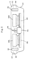
- Figure 5 is a front view showing equipment arrangement in the indoor unit of the air conditioner of Figure 1.
- Figure 6 is a side view showing equipment arrangement in the indoor unit of the air conditioner of Figure 1.
-
- Hereinafter, embodiments of the present invention will be described with reference to the drawings.
- As shown in Figure 1, an indoor unit (1) of an air conditioner of this embodiment is installed at a corner formed by a ceiling (71) and a side wall (72) of a room. The indoor unit (1) is fixedly attached at the casing (10) thereof to the ceiling (71) or the side wall (72) with a fitting described later, though it is not shown in Figure 1.
- The casing (10) is composed of a body (11) formed in a sidewardly long, vertically flattened rectangular parallelepiped and an enlarged portion (13) enlarged downward from the bottom of the body (10). The body (11) of the casing (10) is positioned along the ceiling (71) of the room in its installed condition, and is formed to have a small height so that the amount of protrusion from the ceiling (71) is decreased.
- As shown in Figures 1 and 3, the enlarged portion (13) of the casing (10) is formed at the bottom of the body (11) to gradually protrude downward from front to back of the casing (10). Namely, in the installed condition of the unit, the enlarged portion (13) is formed to gradually protrude downward as it approaches the side wall (72) of the room.
- More specifically, the front or bottom face of the enlarged portion (13) is formed into an inclined surface (14) smoothly downwardly inclining from its front edge continuing to the body (11) to its back face. The casing (10) is formed as a whole so that its front-side portion is thinner than its back-side portion. The back face of the enlarged portion (13) is formed into a vertically raised surface (15) along the side wall (72) of the room, and continues to the back face of the body (11). Both side faces of the enlarged portion (13) continue to respective side portions of the bottom face of the body (11).
- The front edge of the inclined surface (14) of the enlarged portion (13) is positioned slightly backward from the front end of the body (11), while both side edges of the enlarged portion (13) are positioned slightly inward from both side ends of the body (11). As a result, an extended end portion (12) extending frontward and bilaterally of the enlarged portion (13) is formed in the front and both side portions of the casing (11). The extended end portion (12), i.e., the front end portion and both the lateral end portions of the body (11) of the casing (10), is formed to have a slightly round shape by combining bowed surfaces as shown in Figures 3, 5 and 6.
- The casing (10) is formed with a suction opening (41) for sucking room air from below into the casing (10) therethrough and supply openings (43, 44) for supplying conditioned air into the room therethrough. The suction opening (41) is formed in the inclined surface (14) of the enlarged portion (13) of the casing (10). On the other hand, the supply openings (43, 44) are formed to extend from the front face to both the side faces of the body (11) of the casing (10). Out of the supply openings (43, 44), a section opening into the front face of the body (11) forms a front supply opening (43), and sections opening into both the side faces of the body (11) form right and left lateral supply openings (44), respectively. Further, since the body (11) of the casing (10) is formed with the extended end portion (12) as described above, the suction opening (41) and each of the supply openings (43, 44) are positioned a given distance away from each other.
- As shown in the exploded perspective view of Figure 2, the casing (10) is composed of a top plate (10a), a back plate (10b), front plates (10c, 10d) and right and left side plates (10e). The top plate (10a), the back plate (10b) and the front plates (10c, 10d) are members to be integrated so as to be secured to each other. The side plates (10e) are formed detachably from the top plate (10a), the back plate (10b) and the front plates (10c, 10d).
- The front supply opening (43) is formed between both the front plates (10c, 10d), and is provided with a horizontal flap (51). The horizontal flap (51) is held by stays (51a) so that the angle of air supply of the front supply opening (43) can be adjusted. The stays (51a) are provided with a swing unit (51b) for changing the angle of the horizontal flap (51). In addition, in the side plates (10e), the horizontal flap (51) and a swing mechanism (not shown) for adjusting the angle of the horizontal flap (51) are assembled for manual adjustment of the direction of supply of conditioned air at the lateral supply openings (44).
- Inside the casing (10), an air passage (45) is formed for providing air communication from the suction opening (41) to each of the supply openings (43, 44). In the air passage (45), two fans (20R, 20L) for sucking room air from below and discharging it sideward and a heat exchanger (30) for producing conditioned air from the room air are disposed. Below the centrifugal fans (20R, 20L), an air filter (65) is disposed proximate to the suction opening (41).
- Each of the fans (20R, 20L) is formed of a so-called turbo fan which is a kind of centrifugal fan. The fan (20R, 20L) is connected to a drive shaft (26) of a fan motor (25) extending vertically. And, the fan (20R, 20L) is constructed so as to be rotatively driven by the fan motor (25) to suck air from below and discharge it sideward.
- Furthermore, each of the fans (20R, 20L) is fixed to the casing (10) by securing the fan motor (25) to the bottom face of the top plate (10a) of the body (11) of the casing (10). Below each of the fans (20R, 20L), a bell mouth (27) is disposed for guiding room air flowing into the air passage (45) through the suction opening (41) to the corresponding fan (20R, 20L).
- Moreover, the fans (20R, 20L) are arranged in side by side relation and spaced apart from each other widthwise of the body (11) in the body (11) of the casing (10). The casing (10) is provided with a partition (64) between both the centrifugal fans (20R, 20L). In other words, the casing (10) includes the right-hand fan (20R) and the left-hand fan (20L) respectively located on the right and left when viewed from the front of the casing (10) with the partition (64) sandwiched between both the fans (20R, 20L). Both the fans (20R, 20L) are constructed to rotate clockwise when viewed from above the casing (10).
- The heat exchanger (30) is provided inside of the body (11) of the casing (10). As shown in Figure 4, the heat exchanger (30) is formed of a front heat exchange section (31) located in a front-side space of the body (11) of the casing (10) and lateral heat exchange sections (32) located in both lateral-side spaces of the body (11) of the casing (10) to have a substantially U-shape as a whole when viewed in a plan. The heat exchanger (30) is formed into a so-called cross fin heat exchanger composed of a large number of plate-like fins and a heat transfer pipe provided to pass through the fins, though they are not shown in the figure. The fins are arranged in parallel with each other except for corners between the front heat exchange section (31) and the respective lateral heat exchange sections (32). In the corners, the fins gradually change their angles in accordance with the bowed shape of the heat transfer pipe.
- In this embodiment, the heat exchanger (30) is formed in substantially U-shape when viewed in a plan by integrally forming the front heat exchange section (31) and both the lateral heat exchange sections (32). However, the front heat exchange section (31) and both the lateral heat exchange sections (32) may be separate from each other and disposed separately. The fans (20R, 20L) are juxtaposed in a space surrounded by the back face (10b) of the casing (10) and the front and both lateral heat exchange sections (31, 32) of the heat exchanger (30).
- On the top side of the heat exchanger (30), a heat insulator (35) is disposed which is formed in substantially U-shape when viewed in a plan like the heat exchanger (30). On the bottom side of the heat exchanger (30), a drain pan (36) of heat insulating material is disposed which is formed in substantially U-shape when viewed in a plan like the heat exchanger (30). For example, blowing styrol is usable as the material for the heat insulator (35) and the drain pan (36).
- Figures 4 through 6 are layout diagrams showing the positional relationship between various equipment in the casing (10), and schematically show only the outlines of the casing (10) and the equipment. The inside of the enlarged portion (13) is designed as a space for accommodating options (60), for example, so as to accommodate either one of a high-performance air filter and a deodorizer. As the high-performance air filter, an HEPA (high efficiency particulate air) filter, an electrostatic air filter or the like can be used. As the deodorizer, an optical deodorizing unit for deodorizing odorant using photocatalyst may be used.
- In a clearance (S4) between the right- and left-hand centrifugal fans (20R, 20L), a switch box (61) containing switch contacts of internal equipment of the indoor unit (1) is disposed. In place of the switch box (61), a drain pump may be disposed. In addition, in a clearance between the back plate (10b) as a member forming the back face of the casing (19) and both the centrifugal fans (20R, 20L), a refrigerant pipe (62a) and a drain pipe (62b) are provided along the back plate (10b). The reference numeral (63) indicates a pipe cover in which both the pipes (62a, 62b) are run.
- The casing (10) of the indoor unit (1) is constructed so as to be fixable to both of the ceiling (71) and the wall (72) through a fitting (80) shown in Figure 2. The fitting (80) is composed of a plate (81) to be brought into contact with the back plate (10b) of the casing (10) and two arms (82) secured to the plate (81). Though not shown in detail in Figure 2, the arms (82) and the top plate (10a) of the indoor unit (1) are formed with respective through holes corresponding to hanging bolts anchored to the ceiling, and the plate (81) of the fitting (80) is formed with through holes used for securing it to the wall (72) with bolts. Furthermore, the fitting (80) is provided with a temporarily retaining mechanism engaged with the casing (10) of the indoor unit (1).
- When the indoor unit (1) is fixed to the wall (72), the plate (81) of the fitting (80) is first secured to the wall (72), the casing (10) is then temporarily retained to the fitting (80), and the indoor unit (1) is finally secured to the arms (82) through the through holes for the hanging bolts. On the other hand, when the indoor unit (1) is fixed to the ceiling, the fitting (80) is first secured to the hanging bolts, the casing (10) is then temporarily retained to the fitting (80), and the casing (10) is finally secured to the hanging bolts.
- Next, air conditioning operation of the indoor unit (1) will be described. The fans (20R, 20L) are driven into rotation by the fan motors (25) to suck room air through the suction opening (41) into the casing (10). The room air sucked into the casing (10) flows through the air passage (45). The room air flows into the bell mouth (27) and the fans (20R, 20L), flows out sideward of the fans (20R, 20L), and flows toward the supply openings (43, 44).
- The room air passes through the heat exchanger (30) partway toward the supply openings (43, 44). A refrigerant of a refrigerating circuit is circulated through the inside of the heat exchanger (30), though it is not shown. During cooling operation, the refrigerant is heat-exchanged with room air in the heat exchanger (30) and thereby evaporated. The evaporated refrigerant cools the room air to produce conditioned air of low temperature. During heating operation, the refrigerant is heat-exchanged with room air in the heat exchanger (30) and thereby condensed. The condensed refrigerant heats the room air to produce conditioned air of high temperature. Thus, the conditioned air produced in the heat exchanger (30) is supplied to the room in three directions through the supply openings (43, 44).
- Since the suction opening (41) and each supply opening (43, 44) are separated a given distance away from each other, the phenomenon that conditioned air supplied through each supply opening (43, 44) is sucked again through the suction opening (41), namely, a so-called air short-circuit, does never occur.
- According to this embodiment, the two centrifugal fans (20R, 20L) are disposed in the casing (10), and a switch box (61) and a drain pump are disposed in the space (S4) between both the fans. Therefore, the space between the centrifugal fans (20R, 20L) are prevented from being in vain and the space inside the casing (10) can be effectively used. Accordingly, the casing (10) can be downsized.
- Further, since the refrigerant pipe (62a) and the drain pipe (62b) are passed in a space between the back plate (10b) of the casing (10) and both the centrifugal fans (20R, 20L), the space on the back face side of the centrifugal fans (20R, 20L) can be effectively used, thereby downsizing the casing (10). This effect is also attained in the case of a single fan being provided in the casing (10). Furthermore, if the refrigerant pipe (62a) and the drain pipe (62b) are disposed in the above position, external pipes can be connected thereto across the side face of the casing (10). This increases flexibility in installing the indoor unit (1).
- The foregoing embodiment shown in Figure 4 is an example in which the switch box (61) as an air-conditioning part is disposed in the clearance (S4) between the fans (20R, 20L). However, an air-conditioning part such as a switch box (61) may be disposed in a clearance (S1) defined by the back face (10b) of the casing (10), the fans (20R, 20L) and the lateral heat exchange sections (32) (this case includes a single fan (20R, 20L) provided in the casing), or disposed in a clearance (S2) surrounded by the fans (20R, 20L) and the front heat exchange section (31), or disposed in a clearance (S3) surrounded by the back face (10b) of the casing (10) and the fans (20R, 20L).
- The present invention may have the following arrangement with respect to the foregoing embodiment. In the foregoing embodiment, the number of fans (20R, 20L) provided in the casing is two. However, the number of fans provided therein may be one or more than two in accordance with air conditioning capacitance of the indoor unit (1). In the foregoing embodiment, the fan (20R, 20L) is formed of a turbo fan. However, the fan maybe formed of a radial fan or any fan other than the centrifugal fan.
- The casing (10) is not limited to that formed of the body (11) and the enlarged portion (13). For example, the casing may be formed as a whole in a rectangular parallelepiped. Further, the heat exchanger (30) may not necessarily be provided with the front heat exchange section (31) and the lateral heat exchanger sections (32), and may be disposed below the fans (20R, 20L).
- Furthermore, air-conditioning parts arrangeable between the fans (20R, 20L) and the back face of the casing (10) or between the two fans (20R, 20L) are not limited to a switch box (61), a drain pump, a refrigerant pipe (62a) or a drain pipe (62b), and any optional air-conditioning part can be selectively disposed as needed.
- Moreover, when the fan (20R, 20L) is disposed in the casing (10) of the indoor unit (1) provided with the front supply opening (43) and the lateral supply openings (44) like the foregoing embodiment, the corner of the casing (10) is likely to be a dead space regardless of the number of fans (20R, 20L) in use. Therefore, if an air-conditioning part is disposed in the corner, the space inside the casing can be further effectively used, thereby further downsizing the casing (10).
Claims (8)
- An indoor unit of an air conditioner in which a casing (10) is formed with a suction opening (41) for sucking room air from below therethrough, a front supply opening (43) for supplying conditioned air frontward of the casing (10) therethrough, and lateral supply openings (44) for supplying conditioned air bilaterally of the casing (10) therethrough, and the casing (10) is provided internally with a fan (20R, 20L) for sucking and discharging room air and a heat exchanger (30) for producing conditioned air,
wherein one or more air-conditioning parts (62a, 62b) are accommodated in a clearance between a back face (10b) of the casing (10) and the fan (20R, 20L). - The indoor unit of the air conditioner according to Claim 1, wherein the air-conditioning parts are a refrigerant pipe (62a) and a drain pipe (62b).
- An indoor unit of an air conditioner in which a casing (10) is formed with a suction opening (41) for sucking room air from below therethrough, a front supply opening (43) for supplying conditioned air frontward of the casing (10) therethrough, and lateral supply openings (44) for supplying conditioned air bilaterally of the casing (10) therethrough, and the casing (10) is provided internally with a fan (20R, 20L) for sucking and discharging room air and a heat exchanger (30) for producing conditioned air,
wherein the heat exchanger (30) comprises a front heat exchange section (31) disposed along the front supply opening (43) and lateral heat exchange sections (32) disposed along the respective lateral supply openings (44),the fan (20R, 20L) is disposed in a space defined by the back face (10b) of the casing (10) and the front and lateral heat exchange sections (31, 32) of the heat exchanger (30), andan air-conditioning part (61) is disposed in a clearance (S1) defined by the back face (10b) of the casing (10), the fan (20R, 20L) and the lateral heat exchange section (32). - An indoor unit of an air conditioner in which a casing (10) is formed with a suction opening (41) for sucking room air from below therethrough, a front supply opening (43) for supplying conditioned air frontward of the casing (10) therethrough, and lateral supply openings (44) for supplying conditioned air bilaterally of the casing (10) therethrough, and the casing (10) is provided internally with a fan (20R, 20L) for sucking and discharging room air and a heat exchanger (30) for producing conditioned air,
wherein the heat exchanger (30) comprises a front heat exchange section (31) disposed along the front supply opening (43) and lateral heat exchange sections (32) disposed along the respective lateral supply openings (44),a plurality of the fans (20R, 20L) are disposed in side by side relation in a space defined by the back face (10b) of the casing (10) and the front and lateral heat exchange sections (31, 32) of the heat exchanger (30), andan air-conditioning part (61) is disposed in a clearance (S2) surrounded by the front heat exchange section (31) and the adjacent fans (20R, 20L). - An indoor unit of an air conditioner in which a casing (10) is formed with a suction opening (41) for sucking room air from below therethrough, a front supply opening (43) for supplying conditioned air frontward of the casing (10) therethrough, and lateral supply openings (44) for supplying conditioned air bilaterally of the casing (10) therethrough, and the casing (10) is provided internally with a fan (20R, 20L) for sucking and discharging room air and a heat exchanger (30) for producing conditioned air,
wherein the heat exchanger (30) comprises a front heat exchange section (31) disposed along the front supply opening (43) and lateral heat exchange sections (32) disposed along the respective lateral supply openings (44),a plurality of the fans (20R, 20L) are disposed in side by side relation in a space defined by the back face (10b) of the casing (10) and the front and lateral heat exchange sections (31, 32) of the heat exchanger (30), andan air-conditioning part (61) is disposed in a clearance (S3) surrounded by the back face (10b) of the casing (10) and the adjacent fans (20R, 20L). - An indoor unit of an air conditioner in which a casing (10) is formed with a suction opening (41) for sucking room air from below therethrough, a front supply opening (43) for supplying conditioned air frontward of the casing (10) therethrough, and lateral supply openings (44) for supplying conditioned air bilaterally of the casing (10) therethrough, and the casing (10) is provided internally with a fan (20R, 20L) for sucking and discharging room air and a heat exchanger (30) for producing conditioned air,
wherein the heat exchanger (30) comprises a front heat exchange section (31) disposed along the front supply opening (43) and lateral heat exchange sections (32) disposed along the respective lateral supply openings (44),a plurality of the fans (20R, 20L) are disposed in side by side relation in a space defined by the back face (10b) of the casing (10) and the front and lateral heat exchange sections (31, 32) of the heat exchanger (30), andan air-conditioning part (61) is disposed in a clearance (S4) between the adjacent fans (20R, 20L). - The indoor unit of the air conditioner according to any one of Claims 3 through 6, wherein the air-conditioning part is a switch box (61).
- The indoor unit of the air conditioner according to any one of Claims 3 through 6, wherein the air-conditioning part is a drain pump.
Applications Claiming Priority (3)
| Application Number | Priority Date | Filing Date | Title |
|---|---|---|---|
| JP34146198 | 1998-12-01 | ||
| JP10341461A JP3120798B2 (en) | 1998-12-01 | 1998-12-01 | Air conditioner indoor unit |
| PCT/JP1999/006639 WO2000032993A1 (en) | 1998-12-01 | 1999-11-26 | Indoor unit for air conditioner |
Publications (3)
| Publication Number | Publication Date |
|---|---|
| EP1052457A1 true EP1052457A1 (en) | 2000-11-15 |
| EP1052457A4 EP1052457A4 (en) | 2002-05-29 |
| EP1052457B1 EP1052457B1 (en) | 2004-05-26 |
Family
ID=18346254
Family Applications (1)
| Application Number | Title | Priority Date | Filing Date |
|---|---|---|---|
| EP99973113A Expired - Lifetime EP1052457B1 (en) | 1998-12-01 | 1999-11-26 | Indoor unit for air conditioner |
Country Status (7)
| Country | Link |
|---|---|
| EP (1) | EP1052457B1 (en) |
| JP (1) | JP3120798B2 (en) |
| CN (2) | CN1143090C (en) |
| AU (1) | AU740128B2 (en) |
| DE (1) | DE69917605T2 (en) |
| ES (1) | ES2221489T3 (en) |
| WO (1) | WO2000032993A1 (en) |
Cited By (1)
| Publication number | Priority date | Publication date | Assignee | Title |
|---|---|---|---|---|
| US10788240B2 (en) | 2015-10-23 | 2020-09-29 | Samsung Electronics Co., Ltd. | Air conditioner |
Families Citing this family (4)
| Publication number | Priority date | Publication date | Assignee | Title |
|---|---|---|---|---|
| JPH0554798U (en) * | 1991-12-27 | 1993-07-23 | 昭和オリファ株式会社 | Guide rail for shutter |
| CN101619875B (en) * | 2009-07-30 | 2012-01-04 | 广东美的电器股份有限公司 | Indoor machine of split air conditioner |
| JP5794866B2 (en) * | 2011-09-07 | 2015-10-14 | 三菱電機株式会社 | Air conditioner indoor unit |
| AU2015391312B2 (en) * | 2015-04-17 | 2018-11-08 | Mitsubishi Electric Corporation | Indoor unit of air-conditioning apparatus |
Citations (2)
| Publication number | Priority date | Publication date | Assignee | Title |
|---|---|---|---|---|
| GB2155616A (en) * | 1981-10-21 | 1985-09-25 | Mitsubishi Electric Corp | Air conditioning device |
| WO1999043989A1 (en) * | 1998-02-27 | 1999-09-02 | Daikin Industries, Ltd. | Indoor unit for air-conditioners and structure for installing the same |
Family Cites Families (8)
| Publication number | Priority date | Publication date | Assignee | Title |
|---|---|---|---|---|
| JPS594924U (en) * | 1982-06-30 | 1984-01-13 | 西淀空調機株式会社 | Ceiling suspended air conditioning unit |
| JPS6193320A (en) * | 1984-10-12 | 1986-05-12 | Sanyo Electric Co Ltd | Air conditioning unit |
| JPS6315494A (en) | 1986-07-08 | 1988-01-22 | 株式会社東芝 | Through-hole printer for through-hole ceramic board |
| JPS63172817U (en) * | 1987-04-30 | 1988-11-10 | ||
| JPH0457122U (en) * | 1990-09-17 | 1992-05-15 | ||
| JP2501931Y2 (en) * | 1991-12-05 | 1996-06-19 | ダイキン工業株式会社 | Freezers |
| JP3304485B2 (en) * | 1992-05-20 | 2002-07-22 | 東芝キヤリア株式会社 | Indoor unit of air conditioner |
| JPH06193320A (en) * | 1992-07-27 | 1994-07-12 | Takeshi Sofue | Electronic lock |
-
1998
- 1998-12-01 JP JP10341461A patent/JP3120798B2/en not_active Expired - Fee Related
-
1999
- 1999-11-26 ES ES99973113T patent/ES2221489T3/en not_active Expired - Lifetime
- 1999-11-26 DE DE69917605T patent/DE69917605T2/en not_active Expired - Fee Related
- 1999-11-26 WO PCT/JP1999/006639 patent/WO2000032993A1/en active IP Right Grant
- 1999-11-26 CN CNB998025518A patent/CN1143090C/en not_active Expired - Fee Related
- 1999-11-26 AU AU14109/00A patent/AU740128B2/en not_active Ceased
- 1999-11-26 EP EP99973113A patent/EP1052457B1/en not_active Expired - Lifetime
- 1999-12-01 CN CN99257161U patent/CN2400726Y/en not_active Expired - Fee Related
Patent Citations (2)
| Publication number | Priority date | Publication date | Assignee | Title |
|---|---|---|---|---|
| GB2155616A (en) * | 1981-10-21 | 1985-09-25 | Mitsubishi Electric Corp | Air conditioning device |
| WO1999043989A1 (en) * | 1998-02-27 | 1999-09-02 | Daikin Industries, Ltd. | Indoor unit for air-conditioners and structure for installing the same |
Non-Patent Citations (1)
| Title |
|---|
| See also references of WO0032993A1 * |
Cited By (2)
| Publication number | Priority date | Publication date | Assignee | Title |
|---|---|---|---|---|
| US10788240B2 (en) | 2015-10-23 | 2020-09-29 | Samsung Electronics Co., Ltd. | Air conditioner |
| US11629881B2 (en) | 2015-10-23 | 2023-04-18 | Samsung Electronics Co., Ltd. | Air conditioner |
Also Published As
| Publication number | Publication date |
|---|---|
| WO2000032993A1 (en) | 2000-06-08 |
| ES2221489T3 (en) | 2004-12-16 |
| DE69917605T2 (en) | 2004-09-23 |
| JP2000161707A (en) | 2000-06-16 |
| AU1410900A (en) | 2000-06-19 |
| EP1052457B1 (en) | 2004-05-26 |
| AU740128B2 (en) | 2001-11-01 |
| DE69917605D1 (en) | 2004-07-01 |
| CN1143090C (en) | 2004-03-24 |
| JP3120798B2 (en) | 2000-12-25 |
| CN2400726Y (en) | 2000-10-11 |
| CN1289401A (en) | 2001-03-28 |
| EP1052457A4 (en) | 2002-05-29 |
Similar Documents
| Publication | Publication Date | Title |
|---|---|---|
| KR20040010899A (en) | Air Conditioning System | |
| EP1052457B1 (en) | Indoor unit for air conditioner | |
| JP2003207152A (en) | Air conditioner | |
| JP2000018646A (en) | Outdoor unit of air conditioner | |
| JPH1030827A (en) | Air conditioner | |
| JP3750176B2 (en) | Air conditioner outdoor unit | |
| JP3308256B2 (en) | Floor type air conditioner | |
| JP3596422B2 (en) | Indoor unit of air conditioner | |
| JP2005195199A (en) | Air-conditioner | |
| KR100517598B1 (en) | An air-conditioner | |
| JP2003174275A (en) | Control panel of machine tool | |
| KR100525396B1 (en) | air conditioner ventilating room | |
| JPH1026401A (en) | Air-conditioner | |
| KR20070038353A (en) | Ceiling type air conditioner | |
| JP2022001797A (en) | Air conditioner | |
| CN217715188U (en) | Air conditioner | |
| JPS642098Y2 (en) | ||
| JP3972788B2 (en) | Air conditioner indoor unit | |
| JP2003035437A (en) | Outdoor unit for air conditioner | |
| JP3304536B2 (en) | Air conditioner | |
| JPS6128972Y2 (en) | ||
| KR100484936B1 (en) | Air Conditioner | |
| JP2000213763A (en) | Air conditioning unit | |
| KR200312467Y1 (en) | Structure of grill to Air-conditioner filled in ceiling | |
| JPS5977234A (en) | Monoblock type air conditioner |
Legal Events
| Date | Code | Title | Description |
|---|---|---|---|
| PUAI | Public reference made under article 153(3) epc to a published international application that has entered the european phase |
Free format text: ORIGINAL CODE: 0009012 |
|
| 17P | Request for examination filed |
Effective date: 20000804 |
|
| AK | Designated contracting states |
Kind code of ref document: A1 Designated state(s): AT BE CH CY DE DK ES FI FR GB GR IE IT LI LU MC NL PT SE |
|
| A4 | Supplementary search report drawn up and despatched |
Effective date: 20020417 |
|
| AK | Designated contracting states |
Kind code of ref document: A4 Designated state(s): BE DE ES FR GB IT |
|
| RIC1 | Information provided on ipc code assigned before grant |
Free format text: 7F 24F 1/00 A, 7F 24F 13/20 B |
|
| 17Q | First examination report despatched |
Effective date: 20021025 |
|
| GRAP | Despatch of communication of intention to grant a patent |
Free format text: ORIGINAL CODE: EPIDOSNIGR1 |
|
| GRAS | Grant fee paid |
Free format text: ORIGINAL CODE: EPIDOSNIGR3 |
|
| GRAA | (expected) grant |
Free format text: ORIGINAL CODE: 0009210 |
|
| AK | Designated contracting states |
Kind code of ref document: B1 Designated state(s): BE DE ES FR GB IT |
|
| REG | Reference to a national code |
Ref country code: GB Ref legal event code: FG4D |
|
| REF | Corresponds to: |
Ref document number: 69917605 Country of ref document: DE Date of ref document: 20040701 Kind code of ref document: P |
|
| REG | Reference to a national code |
Ref country code: ES Ref legal event code: FG2A Ref document number: 2221489 Country of ref document: ES Kind code of ref document: T3 |
|
| ET | Fr: translation filed | ||
| PLBE | No opposition filed within time limit |
Free format text: ORIGINAL CODE: 0009261 |
|
| STAA | Information on the status of an ep patent application or granted ep patent |
Free format text: STATUS: NO OPPOSITION FILED WITHIN TIME LIMIT |
|
| 26N | No opposition filed |
Effective date: 20050301 |
|
| PGFP | Annual fee paid to national office [announced via postgrant information from national office to epo] |
Ref country code: FR Payment date: 20051108 Year of fee payment: 7 |
|
| PGFP | Annual fee paid to national office [announced via postgrant information from national office to epo] |
Ref country code: GB Payment date: 20051123 Year of fee payment: 7 |
|
| PGFP | Annual fee paid to national office [announced via postgrant information from national office to epo] |
Ref country code: DE Payment date: 20051124 Year of fee payment: 7 |
|
| PGFP | Annual fee paid to national office [announced via postgrant information from national office to epo] |
Ref country code: ES Payment date: 20051219 Year of fee payment: 7 |
|
| PGFP | Annual fee paid to national office [announced via postgrant information from national office to epo] |
Ref country code: BE Payment date: 20060117 Year of fee payment: 7 |
|
| PG25 | Lapsed in a contracting state [announced via postgrant information from national office to epo] |
Ref country code: BE Free format text: LAPSE BECAUSE OF NON-PAYMENT OF DUE FEES Effective date: 20061130 |
|
| PGFP | Annual fee paid to national office [announced via postgrant information from national office to epo] |
Ref country code: IT Payment date: 20061130 Year of fee payment: 8 |
|
| PG25 | Lapsed in a contracting state [announced via postgrant information from national office to epo] |
Ref country code: DE Free format text: LAPSE BECAUSE OF NON-PAYMENT OF DUE FEES Effective date: 20070601 |
|
| GBPC | Gb: european patent ceased through non-payment of renewal fee |
Effective date: 20061126 |
|
| REG | Reference to a national code |
Ref country code: FR Ref legal event code: ST Effective date: 20070731 |
|
| PG25 | Lapsed in a contracting state [announced via postgrant information from national office to epo] |
Ref country code: GB Free format text: LAPSE BECAUSE OF NON-PAYMENT OF DUE FEES Effective date: 20061126 |
|
| BERE | Be: lapsed |
Owner name: *DAIKIN INDUSTRIES LTD Effective date: 20061130 |
|
| REG | Reference to a national code |
Ref country code: ES Ref legal event code: FD2A Effective date: 20061127 |
|
| PG25 | Lapsed in a contracting state [announced via postgrant information from national office to epo] |
Ref country code: FR Free format text: LAPSE BECAUSE OF NON-PAYMENT OF DUE FEES Effective date: 20061130 Ref country code: ES Free format text: LAPSE BECAUSE OF NON-PAYMENT OF DUE FEES Effective date: 20061127 |
|
| PG25 | Lapsed in a contracting state [announced via postgrant information from national office to epo] |
Ref country code: IT Free format text: LAPSE BECAUSE OF NON-PAYMENT OF DUE FEES Effective date: 20071126 |