EP1052389A2 - Method and system for rich condition vapour purge reset based on tank vacuum level condition - Google Patents
Method and system for rich condition vapour purge reset based on tank vacuum level condition Download PDFInfo
- Publication number
- EP1052389A2 EP1052389A2 EP00303727A EP00303727A EP1052389A2 EP 1052389 A2 EP1052389 A2 EP 1052389A2 EP 00303727 A EP00303727 A EP 00303727A EP 00303727 A EP00303727 A EP 00303727A EP 1052389 A2 EP1052389 A2 EP 1052389A2
- Authority
- EP
- European Patent Office
- Prior art keywords
- vapour
- purge
- pressure
- fuel
- tank
- Prior art date
- Legal status (The legal status is an assumption and is not a legal conclusion. Google has not performed a legal analysis and makes no representation as to the accuracy of the status listed.)
- Withdrawn
Links
- 238000010926 purge Methods 0.000 title claims abstract description 82
- 238000000034 method Methods 0.000 title claims abstract description 18
- 239000000446 fuel Substances 0.000 claims abstract description 36
- OKTJSMMVPCPJKN-UHFFFAOYSA-N Carbon Chemical compound [C] OKTJSMMVPCPJKN-UHFFFAOYSA-N 0.000 claims abstract description 16
- 229910052799 carbon Inorganic materials 0.000 claims abstract description 16
- 239000002828 fuel tank Substances 0.000 claims description 26
- 239000007788 liquid Substances 0.000 claims description 3
- 239000003570 air Substances 0.000 description 23
- 230000007423 decrease Effects 0.000 description 6
- 238000002485 combustion reaction Methods 0.000 description 5
- 238000010586 diagram Methods 0.000 description 4
- 230000033228 biological regulation Effects 0.000 description 3
- 230000008859 change Effects 0.000 description 3
- QSHDDOUJBYECFT-UHFFFAOYSA-N mercury Chemical compound [Hg] QSHDDOUJBYECFT-UHFFFAOYSA-N 0.000 description 3
- 229910052753 mercury Inorganic materials 0.000 description 3
- IJGRMHOSHXDMSA-UHFFFAOYSA-N Atomic nitrogen Chemical compound N#N IJGRMHOSHXDMSA-UHFFFAOYSA-N 0.000 description 2
- 239000012080 ambient air Substances 0.000 description 2
- 230000003247 decreasing effect Effects 0.000 description 2
- 230000000994 depressogenic effect Effects 0.000 description 2
- XLYOFNOQVPJJNP-UHFFFAOYSA-N water Substances O XLYOFNOQVPJJNP-UHFFFAOYSA-N 0.000 description 2
- UGFAIRIUMAVXCW-UHFFFAOYSA-N Carbon monoxide Chemical compound [O+]#[C-] UGFAIRIUMAVXCW-UHFFFAOYSA-N 0.000 description 1
- 230000009471 action Effects 0.000 description 1
- 230000015572 biosynthetic process Effects 0.000 description 1
- 229910002091 carbon monoxide Inorganic materials 0.000 description 1
- 239000000470 constituent Substances 0.000 description 1
- 230000001419 dependent effect Effects 0.000 description 1
- 238000003795 desorption Methods 0.000 description 1
- 229930195733 hydrocarbon Natural products 0.000 description 1
- 150000002430 hydrocarbons Chemical class 0.000 description 1
- 230000004941 influx Effects 0.000 description 1
- 239000000203 mixture Substances 0.000 description 1
- 229910052757 nitrogen Inorganic materials 0.000 description 1
- 230000009467 reduction Effects 0.000 description 1
- 230000004044 response Effects 0.000 description 1
- 238000013022 venting Methods 0.000 description 1
Images



Classifications
-
- F—MECHANICAL ENGINEERING; LIGHTING; HEATING; WEAPONS; BLASTING
- F02—COMBUSTION ENGINES; HOT-GAS OR COMBUSTION-PRODUCT ENGINE PLANTS
- F02D—CONTROLLING COMBUSTION ENGINES
- F02D41/00—Electrical control of supply of combustible mixture or its constituents
- F02D41/0025—Controlling engines characterised by use of non-liquid fuels, pluralities of fuels, or non-fuel substances added to the combustible mixtures
- F02D41/003—Adding fuel vapours, e.g. drawn from engine fuel reservoir
- F02D41/0045—Estimating, calculating or determining the purging rate, amount, flow or concentration
-
- F—MECHANICAL ENGINEERING; LIGHTING; HEATING; WEAPONS; BLASTING
- F02—COMBUSTION ENGINES; HOT-GAS OR COMBUSTION-PRODUCT ENGINE PLANTS
- F02D—CONTROLLING COMBUSTION ENGINES
- F02D41/00—Electrical control of supply of combustible mixture or its constituents
- F02D41/0025—Controlling engines characterised by use of non-liquid fuels, pluralities of fuels, or non-fuel substances added to the combustible mixtures
- F02D41/003—Adding fuel vapours, e.g. drawn from engine fuel reservoir
- F02D41/0032—Controlling the purging of the canister as a function of the engine operating conditions
- F02D41/004—Control of the valve or purge actuator, e.g. duty cycle, closed loop control of position
-
- F—MECHANICAL ENGINEERING; LIGHTING; HEATING; WEAPONS; BLASTING
- F02—COMBUSTION ENGINES; HOT-GAS OR COMBUSTION-PRODUCT ENGINE PLANTS
- F02D—CONTROLLING COMBUSTION ENGINES
- F02D41/00—Electrical control of supply of combustible mixture or its constituents
- F02D41/0025—Controlling engines characterised by use of non-liquid fuels, pluralities of fuels, or non-fuel substances added to the combustible mixtures
- F02D41/003—Adding fuel vapours, e.g. drawn from engine fuel reservoir
- F02D41/0042—Controlling the combustible mixture as a function of the canister purging, e.g. control of injected fuel to compensate for deviation of air fuel ratio when purging
Definitions
- the present invention relates to a system for resetting a vapour purge flow rate to prevent rich air/fuel conditions in an engine. More particularly, the present invention relates to a vapour purge flow rate reset system based on fuel tank vacuum level conditions.
- Evaporative emission control is an important consideration in automotive design and necessitates that fuel vapour arising from the engine fuel system be drawn into the engine and burned. Because the fuel vapour can be combusted by the engine, an excessive flow of vapour may cause combustion instability, or perhaps even engine roughness or stalling.
- U.S. Patent No. 5,460,143 discloses an evaporative emissions control system in which a pressure transducer prevents purging of a carbon canister in the event that the fuel tank pressure falls to a negative value.
- U.S. Patent No. 5,816,223 discloses a system in which purging is controlled not only when the tank pressure becomes negative, but in response to rapid fluctuations in the tank pressure - whether at a positive or negative pressure. Rapid fluctuations may cause the air and fuel vapour entering the engine from the purge line of a carbon evaporative emission control canister to alter the combustion process.
- vapour storage purge strategies rely on purge control valves that regulate a constant purge air/vapour mixture flow rate entering the engine for combustion. Constant flow regulation is attempted for vacuum levels ranging from very high to only a few inches of mercury below which the valve flow rate drops off. Under equilibrium conditions, fuel tank vacuum is equal to vapour storage canister system flow restriction. Vapour storage canister system flow restriction is a function of purge air flow through the system.
- vapour storage canister flow restriction levels decreasing which, in turn, decreases the fuel tank vacuum levels.
- the tank vacuum levels decrease by drawing air into, or generating vapour within, the fuel tank vapour space to equalise system vacuums.
- the present invention presents a system for preventing a rich engine air/fuel ratio condition from occurring when there is a change in the purge flow restriction based on engine conditions, i.e. when the throttle is depressed for more engine power.
- the invention is advantageous in that it causes a change in the purge flow restriction based on engine operating conditions. According to the present invention, the foregoing advantages are obtained by introducing a method for comparing the current system pressure against calibrated target levels. The method compares values for a predetermined period of time to determine whether or not the purge duty cycle needs to be reset and adjusted in order to prevent rich engine fuel/air conditions.
- a system embodying the present invention identifies a condition of high possibility of rich engine air/fuel ratio.
- the system monitors engine air mass and determines if purge flow needs to be reset in order to avoid a rich engine air/fuel ratio condition.
- FIG. 1 a schematic diagram of an automotive engine 10 is shown that receives liquid fuel from a fuel tank 12. Vapour generated by fuel contained within the fuel tank 12 and furnished to the engine 10 is controlled by a system according to the present invention. Vapour leaving fuel tank 12 passes through a vapour vent valve 14 and through an outlet port 16 and into a vapour line 18. The vapour then passes to a port 20 of a carbon canister 22.
- fuel vapour is stored within the carbon canister 22.
- ambient air is drawn in and through the carbon canister 22 where it mixes with the fuel vapour and carries it to the engine 10. More specifically, a canister vent valve 24 is open and ambient air is drawn through a purge air inlet 26, then through the carbon canister 22 and through the outlet port 20, through a purge line 28, past a purge valve 30 and into the engine 10.
- An electronic control module (ECM) 32 controls the rate of the purging by operating the purge valve 30 based on information received from a pressure transducer 34.
- Air drawn through the carbon canister 22 causes desorption of fuel vapour stored in the canister.
- the fuel vapour and air flowing from the canister 22 are combined with additional vapours from the fuel tank 12.
- the system attempts to maintain equilibrium whereby the fuel tank vacuum is equal to the vapour storage canister system flow restriction, which, in turn, is a function of the purge air flow through the system.
- the amount of vapour mass drawn from the fuel tank 12 is dependent upon many factors: fuel tank vapour space volume, vapour storage canister flow restriction characteristics, the amount of purge flow lost, the amount of purge flow regained, the rate at which purge flow is regained, the current volatility condition of the fuel within the fuel tank, and the rate at which the tank is allowed to vent. As the overall engine air and fuel consumption rates decrease, the magnitude of impact on engine combustion stability increases for a given influx of purge fuel vapour.
- the system of the present invention utilises the electronic control module (ECM) 32 to calculate an ideal or target vacuum that should be present in the system and compares the calculated vacuum to the actual system pressure. If the engine is determined to be in a sensitive fuel control state, i.e. low fuel consumption, the purge flow is reset and begins to slowly increase flow, thereby slowly drawing vapour from the fuel tank 12 and avoiding a rich engine condition.
- ECM electronice control module
- FIG. 2 through 10 represent aspects of the engine system as the engine load is cycled over time.
- the x-axis in each of the graphs is representative of time measured in seconds.
- the engine load 36 in rpm's, is shown.
- a normal, i.e. light to moderate, engine load 36A is shown at about 700 rpm's for a period of about five (5) seconds.
- the engine load is increased, rather rapidly to a heavy load 36B, around 2000 rpm's, and held for about ten (10) seconds.
- the engine load returns to normal 36C at about fifteen (15) seconds on the graph 36.
- Figures 3 through 10 are graphical representations of how the system reacts to the change in engine load shown in Figure 2.
- Figure 3 is a representation of the intake manifold vacuum 38 in inches of Mercury as it corresponds to the changes in the engine load.
- a sufficient manifold vacuum 38A is produced which allows a full stable purge flow 40A shown in Figure 4 which is a representation of the fraction of full purge flow available.
- Figure 5 is a representation of the engine air consumption rate 42 that shows how the rate increases 42A relative to the increase in the engine load, and decreases 42B as the engine load decreases.
- Figure 6 is a representation of the vapour system pressure 44, in inches of water, as it responds to changes in the engine load.
- the tank vacuum is in equilibrium with the canister flow restriction which results in stable vapour flow 44A being drawn from the fuel tank 12.
- As the reduction in purge flow restriction occurs as a result of increased engine load air is drawn into the fuel tank to equalise the system pressure. Air in contact with the fuel in the tank generates additional vapour mass, thereby decreasing the vapour system vacuum 44B.
- the rapid increase in the purge flow due to the decrease in the engine load results in vapour mass quickly being drawn from the fuel tank to equalise the system pressure, potentially creating a rich engine condition if not for the system and method of the present invention.
- the present invention is a method 100 for identifying the point in time in which the system is at risk of vacuum loss 101 due to purge flow loss and continues to monitor the system to prevent a rich engine condition.
- the method 100 of the present invention is easily followed in the flow chart shown in Figures 11A and 11B.
- the method 100 begins 102 by identifying the point at which the fraction of full purge flow available 40 becomes less than a whole 104. If it is determined that the manifold vacuum has fallen low enough to reduce the canister purge flow, the system determines if a risk flag has been set 106. If not, the system locks in the current purge duty cycle 108 (also shown in the graph in Figure 7) and the vacuum level 110 (also shown in the graph of Figure 8) of the system. Then the system sets the risk flag 112 (shown in the graph of Figure 9), indicating a vacuum loss in the fuel tank has taken place and purge duty cycle and normal system pressure have been locked in.
- the system determines 114 if the current purge duty cycle is high enough to have a purge flow. If not, the system cycles back to the beginning of the vacuum loss risk loop 101.
- the current purge duty cycle locked in at step 108 is compared to a predetermined calibrated purge duty cycle at step 114. If the current purge duty cycle changes the calibrated purge duty cycle, then the system calculates 116 a new target tank pressure based on the current purge duty cycle and current system vacuum levels. The target tank pressure is re-calculated 116 to determine what the expected normal purge flow tank vacuum should be by multiplying the difference between the current purge duty cycle and the calibrated purge duty cycle by the current system tank pressure. The recalculated purge duty cycle is shown in the graph of Figure 10.
- the current purge duty cycle is compared to a calibrated critical purge duty cycle 118. If the current purge duty cycle is not greater then the calibrated critical purge duty cycle, the system returns to the beginning of the vacuum loss risk loop 101. Referring now to Figure 11B, if the current purge duty cycle is greater than the calibrated critical purge duty cycle, the system calculates the difference between the actual system pressure and the target system pressure and compares 120 the target to a critical differential system pressure.
- a countdown timer is loaded 122 and the system returns to step 116, in Figure 11A, where a new target system pressure is calculated.
- the system will determine if the manifold vacuum is sufficient for normal purge flow levels and, at the same time, determine if the countdown timer has reached zero 124. If both of these conditions have been met, the system will loop back to the beginning of the vacuum loss risk loop 101, in Figure 11A. If both of these conditions are not met, the timer is decremented 126 and the system loops back to step 124.
- the purge control loop 200 determines whether or not the purge duty cycle needs to be reset and slowly ramped up to normal levels in order to prevent a rich engine condition.
- the purge control loop 200 is run simultaneously with the vacuum loss risk loop 101.
- condition flag will be reset to zero 126, and the purge flow system will function without intervention 204.
- the system will determine 206 if the engine air mass is lower than a critical air mass value, and if true, the system will reset the purge flow and restart a ramp cycle 208. This action stops vapour from entering the engine. The flow can be slowly restored to full flow, by way of a ramp cycle, thereby preventing an engine rich condition from occurring.
Landscapes
- Engineering & Computer Science (AREA)
- Chemical & Material Sciences (AREA)
- Combustion & Propulsion (AREA)
- Mechanical Engineering (AREA)
- General Engineering & Computer Science (AREA)
- Supplying Secondary Fuel Or The Like To Fuel, Air Or Fuel-Air Mixtures (AREA)
- Electrical Control Of Air Or Fuel Supplied To Internal-Combustion Engine (AREA)
Abstract
A system and method for controlling the purging of
vapour from a carbon canister (22) based on identification
of a vacuum loss in the manifold. The system and method of
the present invention store target values for the tank
pressure and purge duty cycle. A differential pressure
between current system levels and target levels is
calculated and compared to predetermined critical levels.
If the currently calculated level exceeds a calibrated
threshold value, a countdown timer is set and reset until
the calculated differential drops below the threshold value.
If the engine air mass drops below a critical calibrated air
mass value before the timer has completed counting down, the
purge flow is reset and slowly reintroduced to prevent rich
engine air/fuel ratio conditions.
Description
- The present invention relates to a system for resetting a vapour purge flow rate to prevent rich air/fuel conditions in an engine. More particularly, the present invention relates to a vapour purge flow rate reset system based on fuel tank vacuum level conditions.
- Government regulations concerning the release into the atmosphere of various exhaust emission constituents from automotive vehicles are becoming increasingly more stringent. As the regulations relating to emissions of oxides of nitrogen, carbon monoxide, and unburned hydrocarbons become more stringent, it is necessary to control the engine combustion process to avoid unnecessary instabilities and thus prevent formation of undesirable exhaust emissions.
- Evaporative emission control is an important consideration in automotive design and necessitates that fuel vapour arising from the engine fuel system be drawn into the engine and burned. Because the fuel vapour can be combusted by the engine, an excessive flow of vapour may cause combustion instability, or perhaps even engine roughness or stalling.
- U.S. Patent No. 5,460,143 discloses an evaporative emissions control system in which a pressure transducer prevents purging of a carbon canister in the event that the fuel tank pressure falls to a negative value. U.S. Patent No. 5,816,223 discloses a system in which purging is controlled not only when the tank pressure becomes negative, but in response to rapid fluctuations in the tank pressure - whether at a positive or negative pressure. Rapid fluctuations may cause the air and fuel vapour entering the engine from the purge line of a carbon evaporative emission control canister to alter the combustion process.
- Some fuel system vapour storage purge strategies rely on purge control valves that regulate a constant purge air/vapour mixture flow rate entering the engine for combustion. Constant flow regulation is attempted for vacuum levels ranging from very high to only a few inches of mercury below which the valve flow rate drops off. Under equilibrium conditions, fuel tank vacuum is equal to vapour storage canister system flow restriction. Vapour storage canister system flow restriction is a function of purge air flow through the system.
- When the manifold vacuum falls below the constant purge flow vacuum levels, such as when the throttle is depressed for more engine power, significant purge flow can be lost. This loss in purge flow results in vapour storage canister flow restriction levels decreasing which, in turn, decreases the fuel tank vacuum levels. The tank vacuum levels decrease by drawing air into, or generating vapour within, the fuel tank vapour space to equalise system vacuums.
- When the manifold vacuum increases, purge flow increases which creates higher vapour storage canister system flow restrictions. Fuel vapour mass must be drawn from the fuel tank vapour space in order to equalise the system vacuum levels. If a sufficiently large enough vapour mass is drawn from the fuel tank, undesirable rich engine air/fuel ratio conditions are created.
- The present invention presents a system for preventing a rich engine air/fuel ratio condition from occurring when there is a change in the purge flow restriction based on engine conditions, i.e. when the throttle is depressed for more engine power.
- The invention is advantageous in that it causes a change in the purge flow restriction based on engine operating conditions. According to the present invention, the foregoing advantages are obtained by introducing a method for comparing the current system pressure against calibrated target levels. The method compares values for a predetermined period of time to determine whether or not the purge duty cycle needs to be reset and adjusted in order to prevent rich engine fuel/air conditions.
- A system embodying the present invention identifies a condition of high possibility of rich engine air/fuel ratio. The system monitors engine air mass and determines if purge flow needs to be reset in order to avoid a rich engine air/fuel ratio condition.
- The invention will now be described, by way of example, with reference to the accompanying drawings, in which:
- Figure 1 is a schematic diagram of an automotive engine having a fuel vapour venting and carbon canister purging system according to the present invention;
- Figure 2 is a graph of engine load in rpm's;
- Figure 3 is a graph of the intake manifold vacuum in inches of Mercury;
- Figure 4 is a graph of the fraction of purge flow available;
- Figure 5 is a graph of the air mass, also known as the engine air consumption rate;
- Figure 6 is a graph of the vapour system pressure in inches of water;
- Figure 7 is a graph of the purge duty cycle that is stored according to the method of the present invention;
- Figure 8 is a graph of the fuel tank pressure that is stored according to the method of the present invention;
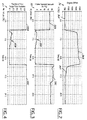
- Figure 9 is a graph of the vacuum loss condition flag as it is set and reset in the present invention;
- Figure 10 is a graph of the target vacuum as it is recalculated according to the method of the present invention;
- Figures 11A and 11B are a flow diagram illustrating the operation of the method of the present invention; and
- Figure 12 is a flow diagram of the purge control loop of the present invention.
-
- Referring to Figure 1, a schematic diagram of an
automotive engine 10 is shown that receives liquid fuel from afuel tank 12. Vapour generated by fuel contained within thefuel tank 12 and furnished to theengine 10 is controlled by a system according to the present invention. Vapour leavingfuel tank 12 passes through avapour vent valve 14 and through anoutlet port 16 and into avapour line 18. The vapour then passes to aport 20 of acarbon canister 22. - When the engine is not being operated, fuel vapour is stored within the
carbon canister 22. When the engine is being operated, ambient air is drawn in and through thecarbon canister 22 where it mixes with the fuel vapour and carries it to theengine 10. More specifically, acanister vent valve 24 is open and ambient air is drawn through apurge air inlet 26, then through thecarbon canister 22 and through theoutlet port 20, through apurge line 28, past a purge valve 30 and into theengine 10. An electronic control module (ECM) 32 controls the rate of the purging by operating the purge valve 30 based on information received from apressure transducer 34. - Air drawn through the
carbon canister 22 causes desorption of fuel vapour stored in the canister. The fuel vapour and air flowing from thecanister 22 are combined with additional vapours from thefuel tank 12. The system attempts to maintain equilibrium whereby the fuel tank vacuum is equal to the vapour storage canister system flow restriction, which, in turn, is a function of the purge air flow through the system. - The amount of vapour mass drawn from the
fuel tank 12 is dependent upon many factors: fuel tank vapour space volume, vapour storage canister flow restriction characteristics, the amount of purge flow lost, the amount of purge flow regained, the rate at which purge flow is regained, the current volatility condition of the fuel within the fuel tank, and the rate at which the tank is allowed to vent. As the overall engine air and fuel consumption rates decrease, the magnitude of impact on engine combustion stability increases for a given influx of purge fuel vapour. - The system of the present invention utilises the electronic control module (ECM) 32 to calculate an ideal or target vacuum that should be present in the system and compares the calculated vacuum to the actual system pressure. If the engine is determined to be in a sensitive fuel control state, i.e. low fuel consumption, the purge flow is reset and begins to slowly increase flow, thereby slowly drawing vapour from the
fuel tank 12 and avoiding a rich engine condition. - The system and method of the present invention can best be described by an example of the operation of an engine as it cycles from a normal load to a heavy load and back to a normal load. Figures 2 through 10 represent aspects of the engine system as the engine load is cycled over time. The x-axis in each of the graphs is representative of time measured in seconds.
- Referring to Figure 2 the
engine load 36, in rpm's, is shown. A normal, i.e. light to moderate,engine load 36A is shown at about 700 rpm's for a period of about five (5) seconds. After about five (5) seconds, the engine load is increased, rather rapidly to aheavy load 36B, around 2000 rpm's, and held for about ten (10) seconds. The engine load returns to normal 36C at about fifteen (15) seconds on thegraph 36. - In general, Figures 3 through 10 are graphical representations of how the system reacts to the change in engine load shown in Figure 2. Figure 3 is a representation of the intake manifold vacuum 38 in inches of Mercury as it corresponds to the changes in the engine load. As shown by the first five seconds of the graph in Figure 3, a
sufficient manifold vacuum 38A is produced which allows a fullstable purge flow 40A shown in Figure 4 which is a representation of the fraction of full purge flow available. - When the period of heavy engine load occurs, between five (5) and fifteen (15) seconds in the present example, the manifold vacuum is reduced, shown by 38B in Figure 3, which causes the purge flow to drop off, shown by 40B in Figure 4. As the engine load is rapidly reduced at about fifteen (15) seconds, the manifold vacuum increases as shown by 38C in Figure 3. The increased manifold vacuum causes the purge flow to return to full flow levels, shown by 40C in Figure 4.
- Figure 5 is a representation of the engine
air consumption rate 42 that shows how the rate increases 42A relative to the increase in the engine load, and decreases 42B as the engine load decreases. - Figure 6 is a representation of the
vapour system pressure 44, in inches of water, as it responds to changes in the engine load. The tank vacuum is in equilibrium with the canister flow restriction which results instable vapour flow 44A being drawn from thefuel tank 12. As the reduction in purge flow restriction occurs as a result of increased engine load, air is drawn into the fuel tank to equalise the system pressure. Air in contact with the fuel in the tank generates additional vapour mass, thereby decreasing thevapour system vacuum 44B. The rapid increase in the purge flow due to the decrease in the engine load results in vapour mass quickly being drawn from the fuel tank to equalise the system pressure, potentially creating a rich engine condition if not for the system and method of the present invention. - The present invention is a
method 100 for identifying the point in time in which the system is at risk ofvacuum loss 101 due to purge flow loss and continues to monitor the system to prevent a rich engine condition. Themethod 100 of the present invention is easily followed in the flow chart shown in Figures 11A and 11B. Referring first to Figure 11A, themethod 100 begins 102 by identifying the point at which the fraction of full purge flow available 40 becomes less than a whole 104. If it is determined that the manifold vacuum has fallen low enough to reduce the canister purge flow, the system determines if a risk flag has been set 106. If not, the system locks in the current purge duty cycle 108 (also shown in the graph in Figure 7) and the vacuum level 110 (also shown in the graph of Figure 8) of the system. Then the system sets the risk flag 112 (shown in the graph of Figure 9), indicating a vacuum loss in the fuel tank has taken place and purge duty cycle and normal system pressure have been locked in. - When the flag is set 112, the system determines 114 if the current purge duty cycle is high enough to have a purge flow. If not, the system cycles back to the beginning of the vacuum
loss risk loop 101. - Referring again to Figure 11A, the current purge duty cycle locked in at
step 108 is compared to a predetermined calibrated purge duty cycle atstep 114. If the current purge duty cycle changes the calibrated purge duty cycle, then the system calculates 116 a new target tank pressure based on the current purge duty cycle and current system vacuum levels. The target tank pressure is re-calculated 116 to determine what the expected normal purge flow tank vacuum should be by multiplying the difference between the current purge duty cycle and the calibrated purge duty cycle by the current system tank pressure. The recalculated purge duty cycle is shown in the graph of Figure 10. - Next, the current purge duty cycle is compared to a calibrated critical
purge duty cycle 118. If the current purge duty cycle is not greater then the calibrated critical purge duty cycle, the system returns to the beginning of the vacuumloss risk loop 101. Referring now to Figure 11B, if the current purge duty cycle is greater than the calibrated critical purge duty cycle, the system calculates the difference between the actual system pressure and the target system pressure and compares 120 the target to a critical differential system pressure. - If the calculated differential pressure is greater than the critical differential system pressure and the current duty cycle is greater than a minimum threshold purge duty cycle, a countdown timer is loaded 122 and the system returns to step 116, in Figure 11A, where a new target system pressure is calculated.
- If the calculated differential pressure is not greater than the calibrated differential pressure, the system will determine if the manifold vacuum is sufficient for normal purge flow levels and, at the same time, determine if the countdown timer has reached zero 124. If both of these conditions have been met, the system will loop back to the beginning of the vacuum
loss risk loop 101, in Figure 11A. If both of these conditions are not met, the timer is decremented 126 and the system loops back tostep 124. - The
purge control loop 200, shown in Figure 12, determines whether or not the purge duty cycle needs to be reset and slowly ramped up to normal levels in order to prevent a rich engine condition. Thepurge control loop 200 is run simultaneously with the vacuumloss risk loop 101. - If normal purge flow levels have returned, and the timer has counted to zero 202, the condition flag will be reset to zero 126, and the purge flow system will function without
intervention 204. - If normal flow has not been restored and the timer has not yet reached zero, the system will determine 206 if the engine air mass is lower than a critical air mass value, and if true, the system will reset the purge flow and restart a
ramp cycle 208. This action stops vapour from entering the engine. The flow can be slowly restored to full flow, by way of a ramp cycle, thereby preventing an engine rich condition from occurring.
Claims (7)
- An evaporative emission control system for providing fuel vapour to an automotive engine, said system comprising:a liquid fuel storage tank (12) having an outlet port (16) for allowing fuel vapour to exit the tank (12);a carbon canister (22) for storing fuel vapour generated within the fuel tank (12), with the carbon canister having an inlet port (26) for receiving air and an outlet port (20), said outlet port being adapted for both receiving fuel vapour from said fuel tank and acting as an outlet for stored fuel vapour and air when said carbon canister (12) is purged;a vapour line (18) connecting said tank outlet port (16) to said outlet port of said carbon canister;a purge valve (30) for allowing vapour to flow from said fuel tank (12) and said outlet port (20) of said carbon canister (22) through a purge line (28) and into said engine (10);a pressure transducer (34) for sensing a purge system pressure within said vapour line; anda controller (32) connected to said purge valve (30) and said pressure transducer (34), said controller (32) comparing a calculated differential system pressure with a predetermined calibrated differential system pressure and resetting said purge valve (30) based on said compared differential pressures.
- A system according to claim 1, wherein said controller begins comparing said differential pressures in the event a loss of system vacuum is identified.
- A system according to claim 1, wherein said controller calculates a target tank pressure based on a current purge duty cycle stored in the event a risk of vacuum loss exists in said system.
- A system according to claim 1, wherein said purge valve is reset in the event a measured air mass has dropped below a predetermined critical air mass value before a predetermined period of time has expired.
- A method for controlling a flow of evaporative fuel vapour to an automotive engine having a liquid fuel storage tank, a carbon vapour storage canister, and a purge system for conveying fuel vapour to the engine from the fuel tank and the carbon canister, said method comprising the steps of:identifying a risk of vacuum loss in the fuel tank;storing a current purge duty cycle and a current tank pressure;calculating a differential system pressure;comparing said differential system pressure to a predetermined calibrated differential system pressure; andadjusting said flow of purged vapour to said engine in the event that said calculated differential pressure drops below said predetermined calibrated differential pressure and a measured air mass value drops below a predetermined critical air mass value before a predetermined period of time has expired.
- A method as claimed in claim 5, wherein said step of calculating a differential pressure further comprises calculating a target tank pressure based on said stored purge duty cycle.
- A method as claimed in claim 5, wherein said step of adjusting said flow of fuel vapour further comprises the step of loading a countdown timer in the event said calculated differential pressure remains greater than said predetermined calibrated differential pressure.
Applications Claiming Priority (2)
| Application Number | Priority Date | Filing Date | Title |
|---|---|---|---|
| US09/307,442 US6189515B1 (en) | 1999-05-10 | 1999-05-10 | Method and system for rich condition vapor purge reset based on tank vacuum level condition |
| US307442 | 1999-05-10 |
Publications (1)
| Publication Number | Publication Date |
|---|---|
| EP1052389A2 true EP1052389A2 (en) | 2000-11-15 |
Family
ID=23189792
Family Applications (1)
| Application Number | Title | Priority Date | Filing Date |
|---|---|---|---|
| EP00303727A Withdrawn EP1052389A2 (en) | 1999-05-10 | 2000-05-03 | Method and system for rich condition vapour purge reset based on tank vacuum level condition |
Country Status (2)
| Country | Link |
|---|---|
| US (1) | US6189515B1 (en) |
| EP (1) | EP1052389A2 (en) |
Families Citing this family (5)
| Publication number | Priority date | Publication date | Assignee | Title |
|---|---|---|---|---|
| JP2001041114A (en) * | 1999-07-26 | 2001-02-13 | Honda Motor Co Ltd | Evaporative fuel release prevention device for internal combustion engine |
| US9279397B2 (en) | 2013-10-31 | 2016-03-08 | Ford Global Technologies, Llc | System and methods for canister purging with low manifold vacuum |
| US9050885B1 (en) | 2013-12-09 | 2015-06-09 | Ford Global Technologies, Llc | Systems and methods for managing bleed emissions in plug-in hybrid electric vehicles |
| US9145051B2 (en) | 2013-12-09 | 2015-09-29 | Ford Global Technologies, Llc | Systems and methods for managing bleed emissions in plug-in hybrid electric vehicles |
| CN109269588B (en) * | 2018-10-17 | 2021-01-05 | 奇瑞汽车股份有限公司 | Carbon canister desorption volume measuring equipment and measuring method |
Citations (2)
| Publication number | Priority date | Publication date | Assignee | Title |
|---|---|---|---|---|
| US5460143A (en) | 1993-10-30 | 1995-10-24 | Suzuki Motor Corporation | Fault-diagnosing device for evaporation system |
| US5816223A (en) | 1997-12-29 | 1998-10-06 | Ford Global Technologies, Inc. | Evaporative emission control system for providing fuel to vapor to automotive engine |
Family Cites Families (8)
| Publication number | Priority date | Publication date | Assignee | Title |
|---|---|---|---|---|
| JP2551222B2 (en) * | 1990-10-15 | 1996-11-06 | トヨタ自動車株式会社 | Failure diagnosis device for evaporation purge system |
| GB2254318B (en) * | 1991-04-02 | 1995-08-09 | Nippon Denso Co | Abnormality detecting apparatus for use in fuel transpiration preventing system |
| JP3116556B2 (en) * | 1992-06-08 | 2000-12-11 | 株式会社デンソー | Airtightness check device for fuel tank system of internal combustion engine |
| JPH07119559A (en) * | 1993-10-26 | 1995-05-09 | Mitsubishi Electric Corp | Control device for internal combustion engine |
| JPH08334065A (en) * | 1995-06-05 | 1996-12-17 | Honda Motor Co Ltd | Evaporative fuel processor |
| US5718210A (en) * | 1995-07-31 | 1998-02-17 | Toyota Jidosha Kabushiki Kaisha | Testing apparatus for fuel vapor treating device |
| DE19701353C1 (en) * | 1997-01-16 | 1998-03-12 | Siemens Ag | Motor vehicle IC engine fuel-tank ventilation |
| US6047688A (en) * | 1999-01-15 | 2000-04-11 | Daimlerchrysler Corporation | Method of determining the purge canister mass |
-
1999
- 1999-05-10 US US09/307,442 patent/US6189515B1/en not_active Expired - Fee Related
-
2000
- 2000-05-03 EP EP00303727A patent/EP1052389A2/en not_active Withdrawn
Patent Citations (2)
| Publication number | Priority date | Publication date | Assignee | Title |
|---|---|---|---|---|
| US5460143A (en) | 1993-10-30 | 1995-10-24 | Suzuki Motor Corporation | Fault-diagnosing device for evaporation system |
| US5816223A (en) | 1997-12-29 | 1998-10-06 | Ford Global Technologies, Inc. | Evaporative emission control system for providing fuel to vapor to automotive engine |
Also Published As
| Publication number | Publication date |
|---|---|
| US6189515B1 (en) | 2001-02-20 |
Similar Documents
| Publication | Publication Date | Title |
|---|---|---|
| US6874485B2 (en) | Device for detecting canister deterioration | |
| US6880534B2 (en) | Evaporative fuel processing system | |
| US6338336B1 (en) | Engine air-fuel ratio control with fuel vapor pressure-based feedback control feature | |
| US5460143A (en) | Fault-diagnosing device for evaporation system | |
| JPH06200842A (en) | Method and device for controlling engine idle speed | |
| US5988150A (en) | Evaporated fuel treatment device of engine | |
| US6189515B1 (en) | Method and system for rich condition vapor purge reset based on tank vacuum level condition | |
| US6701906B2 (en) | System and method for controlling fuel injection | |
| US5816223A (en) | Evaporative emission control system for providing fuel to vapor to automotive engine | |
| JPH08144870A (en) | Evaporative fuel treatment system for internal combustion engine | |
| JP4622707B2 (en) | Evaporative gas processing equipment | |
| US5562083A (en) | Fuel vapor emission control device for engine | |
| KR100428112B1 (en) | Method for canister purge controlling of engine in vehicle | |
| US5806507A (en) | Evaporated fuel treatment device of an engine | |
| JPH10299583A (en) | Evaporative fuel release prevention device for internal combustion engine | |
| US6595190B1 (en) | System and method for controlling release of fuel vapor from a vapor recovery system | |
| KR100774350B1 (en) | Canister Fuzzy Control and Method in Vehicle | |
| JP3003449B2 (en) | Fuel vapor purge amount control device for fuel vapor processing system | |
| JP3500693B2 (en) | Fuel vapor purge amount control device for fuel vapor processing system | |
| KR100218784B1 (en) | Fuzzy valve control method | |
| JP3444006B2 (en) | Evaporative fuel treatment system for internal combustion engine | |
| US8116931B2 (en) | Fast fuel adjustment system diagnostic systems and methods | |
| JP3325457B2 (en) | Evaporative fuel processing device | |
| JPH1030507A (en) | Evaporative fuel treatment system for internal combustion engines | |
| US6443138B1 (en) | Full range fuel shift determination |
Legal Events
| Date | Code | Title | Description |
|---|---|---|---|
| PUAI | Public reference made under article 153(3) epc to a published international application that has entered the european phase |
Free format text: ORIGINAL CODE: 0009012 |
|
| AK | Designated contracting states |
Kind code of ref document: A2 Designated state(s): AT BE CH CY DE DK ES FI FR GB GR IE IT LI LU MC NL PT SE |
|
| AX | Request for extension of the european patent |
Free format text: AL;LT;LV;MK;RO;SI |
|
| STAA | Information on the status of an ep patent application or granted ep patent |
Free format text: STATUS: THE APPLICATION HAS BEEN WITHDRAWN |
|
| 18W | Application withdrawn |
Effective date: 20040523 |