EP1052168A2 - Rotary actuator and system - Google Patents
Rotary actuator and system Download PDFInfo
- Publication number
- EP1052168A2 EP1052168A2 EP00303976A EP00303976A EP1052168A2 EP 1052168 A2 EP1052168 A2 EP 1052168A2 EP 00303976 A EP00303976 A EP 00303976A EP 00303976 A EP00303976 A EP 00303976A EP 1052168 A2 EP1052168 A2 EP 1052168A2
- Authority
- EP
- European Patent Office
- Prior art keywords
- drive
- arrangement
- rotary actuator
- movement
- output
- Prior art date
- Legal status (The legal status is an assumption and is not a legal conclusion. Google has not performed a legal analysis and makes no representation as to the accuracy of the status listed.)
- Withdrawn
Links
Images



Classifications
-
- B—PERFORMING OPERATIONS; TRANSPORTING
- B64—AIRCRAFT; AVIATION; COSMONAUTICS
- B64D—EQUIPMENT FOR FITTING IN OR TO AIRCRAFT; FLIGHT SUITS; PARACHUTES; ARRANGEMENT OR MOUNTING OF POWER PLANTS OR PROPULSION TRANSMISSIONS IN AIRCRAFT
- B64D45/00—Aircraft indicators or protectors not otherwise provided for
- B64D45/0005—Devices specially adapted to indicate the position of a movable element of the aircraft, e.g. landing gear
-
- B—PERFORMING OPERATIONS; TRANSPORTING
- B64—AIRCRAFT; AVIATION; COSMONAUTICS
- B64D—EQUIPMENT FOR FITTING IN OR TO AIRCRAFT; FLIGHT SUITS; PARACHUTES; ARRANGEMENT OR MOUNTING OF POWER PLANTS OR PROPULSION TRANSMISSIONS IN AIRCRAFT
- B64D45/00—Aircraft indicators or protectors not otherwise provided for
- B64D45/0005—Devices specially adapted to indicate the position of a movable element of the aircraft, e.g. landing gear
- B64D2045/001—Devices specially adapted to indicate the position of a movable element of the aircraft, e.g. landing gear for indicating symmetry of flaps deflection
-
- Y—GENERAL TAGGING OF NEW TECHNOLOGICAL DEVELOPMENTS; GENERAL TAGGING OF CROSS-SECTIONAL TECHNOLOGIES SPANNING OVER SEVERAL SECTIONS OF THE IPC; TECHNICAL SUBJECTS COVERED BY FORMER USPC CROSS-REFERENCE ART COLLECTIONS [XRACs] AND DIGESTS
- Y10—TECHNICAL SUBJECTS COVERED BY FORMER USPC
- Y10T—TECHNICAL SUBJECTS COVERED BY FORMER US CLASSIFICATION
- Y10T74/00—Machine element or mechanism
- Y10T74/19—Gearing
- Y10T74/19023—Plural power paths to and/or from gearing
- Y10T74/19074—Single drive plural driven
- Y10T74/19079—Parallel
- Y10T74/19084—Spur
-
- Y—GENERAL TAGGING OF NEW TECHNOLOGICAL DEVELOPMENTS; GENERAL TAGGING OF CROSS-SECTIONAL TECHNOLOGIES SPANNING OVER SEVERAL SECTIONS OF THE IPC; TECHNICAL SUBJECTS COVERED BY FORMER USPC CROSS-REFERENCE ART COLLECTIONS [XRACs] AND DIGESTS
- Y10—TECHNICAL SUBJECTS COVERED BY FORMER USPC
- Y10T—TECHNICAL SUBJECTS COVERED BY FORMER US CLASSIFICATION
- Y10T74/00—Machine element or mechanism
- Y10T74/19—Gearing
- Y10T74/19023—Plural power paths to and/or from gearing
- Y10T74/19074—Single drive plural driven
- Y10T74/19112—Aligned
Definitions
- This invention relates to a rotary actuator and system.
- the invention is particularly suitable for use in aerospace applications, for example for use in moving the flaps, hatches or doors of an aircraft.
- a pair of rotary actuators are driven by a common drive shaft, the actuators being connected to respective levers or arms mounted adjacent opposite ends or edges of the flap.
- the actuators associated with each flap may be driven by a common drive shaft.
- the provision of two rotary actuators associated with each flap results in the actuator system being heavy. It is an object of the invention to provide an actuator system of reduced weight. It is a further object of the invention to provide an actuator suitable for use in such an actuator system which permits the detection of a fault indicative of a skew condition, and to provide a skew detection system suitable for use with other actuator systems.
- an actuator system comprising a rotary actuator having an input, a first output, and a second output, the first and second outputs being arranged to move at substantially the same angular speed upon rotation of the input, a drive shaft coupled to the input, and first and second output shafts coupled, respectively, to the first and second outputs.
- the first and second output shafts may be coupled, in use, to respective arms or levers associated with opposite edges of a flap.
- Such an actuator system is advantageous in that a single rotary actuator is associated with each flap. As a result, the actuator system is of reduced weight.
- the first and second output shafts conveniently comprise torque tubes.
- the drive shaft conveniently extends through at least one of the torque tubes.
- a rotary actuator comprising an input, a drive member angularly moveable within a housing in response to rotation of the input, first and second angularly moveable outputs, and a drive arrangement for transmitting movement of the drive member to the first and second outputs.
- the drive arrangement conveniently comprises a differential drive arrangement permitting limited relative angular movement of the first and second outputs.
- the differential drive arrangement conveniently comprises a "dog bone" differential drive arrangement.
- the rotary actuator further comprises a detection arrangement arranged to produce an output signal in the event that relative angular movement occurs between the first and second outputs.
- the second output may include a member spring biased towards the drive member, the detector arrangement including a ball/ramp arrangement arranged to drive the said member of the second output against the action of the spring biasing in the event of relative angular movement occurring between the first and second outputs, and a position sensor arranged to monitor the position of the said member.
- one of the output shafts may carry an annular member, the detection arrangement including a C-spring arrangement arranged to act on the annular member.
- the drive member of the rotary actuator may be provided with at least one aperture for receiving a roller member, the roller member being engaged between the C-spring arrangement and the annular member.
- the C-spring arrangement may include a plurality of C-springs.
- the detection arrangement may comprise at least one detent member received within a recess provided in the drive member and engaging a surface of the plate member, the detection arrangement being arranged such that, in the event of relative angular movement between the first and second outputs, relative movement between the annular member and the drive member causes the detent member to ride out of the recess, thereby causing movement of the plate member.
- a position sensor may be employed to sense the position of the plate member. In the event of a skew condition arising, relative angular movement will occur between the first and second outputs, and as a result the plate member will move, the movement being detected by the position sensor which generates a signal indicative of the presence of a skew condition.
- a detection arrangement for use with a rotary actuator as described herein, the detection arrangement comprising first and second angularly moveable members, a ball and ramp arrangement arranged such that, upon relative angular movement occurring between the first and second members, one of the first and second members moves axially, and a position sensor arranged to provide an output signal in the event that axial movement of the said one of the first and second members is detected.
- a detection arrangement for use with a rotary actuator as herein described, the detection arrangement comprising first and second angularly moveable members and a plate member arranged such that, upon relative angular movement occurring between the first and second members, the plate member is caused to move, a position sensor being arranged to provide an output signal in the event that movement of the plate member is detected.
- first and second members of the detection arrangement may be coupled to one another by a differential drive arrangement, for example a dog bone differential drive arrangement.
- FIG. 1 illustrates a leading edge high lift flap system for use with an aircraft.
- the system comprises a plurality of flaps 1 which are pivotally mounted upon an aircraft wing.
- Each flap 1 has associated therewith a pair of lever arms 2 which are pivotally mounted upon the aircraft wing, the arms 2 cooperating with the flap 1 such that pivotal movement of the arms 2 causes the flap 1 to move relative to the wing.
- each arm 2 is mounted for pivotal movement relative to the wing by means of bearings 3.
- the arms 2 are arranged to be driven, in use, by a rotary actuator 4, the actuator 4 having a pair of outputs, each output having connected thereto, a carbon fibre reinforced plastic high torque low speed torque tube 5, the end of which remote from the actuator 4 is secured to an input of a respective one of the arms 2 to drive the arms 2 for pivotal movement relative to the wing.
- the rotary actuator 4 includes an input which is driven, in use, by a drive shaft 6.
- the drive shaft 6 is common to a plurality of flaps 1 and is arranged to be driven by a power drive unit 7 under the control of an appropriate control arrangement.
- the power drive unit 7 is located approximately half way along the length of the drive shaft 6, and the ends of the drive shaft 6 have associated therewith a position sensor 8 which is arranged to detect rotational movement of the ends of the drive shaft 6, thus permitting detection of the failure of the drive shaft between the power drive unit 7 and the sensor 8.
- the drive shaft 6 extends substantially coaxially with the torque tubes 5, the drive shaft 6 extending through the torque tubes 5.
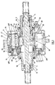
- FIG 3 is a sectional view of the rotary actuator 4 illustrated in Figures 1, 1 a and 2.
- the rotary actuator 4 comprises a two-part housing 9 a , 9 b having first and second output members 10, 11 protruding therefrom.
- Bearings 12 are provided to rotatably mount the output members 10, 11 to the housing parts 9 a , 9 b and seal arrangements 13 are provided between the housing parts 9 a , 9 b and the first and second output members 10, 11.
- Rotatably mounted within the first and second outlet members 10, 11 is an input member 14, bearings 15 supporting the input member 14 for rotation relative to the first and second output members 10, 11.
- Appropriate seals 16 are also provided between the input member 14 and the output members 10, 11.
- the input member 14 protrudes from both the first and second output members 10, 11, the ends of the input member 14 being shaped to form connectors whereby the component parts forming the drive shaft 6 can be secured to the input member 14 to drive the input member 14 for rotation relative to the housing parts 9 a , 9 b .
- the input member 14 is shaped to define an integral gear 17 which meshes with gears 18 mounted upon a carrier 18 a located within the housing 9 defined by the housing parts 9 a , 9 b , the gears 18 being supported for rotation upon the carrier 18 a by means of suitable bearings 19. As illustrated in Figure 3, the gears 18 extend through slots 20 formed in the first output member 10.
- the first and second output members 10, 11 are intended to move only through a relatively restricted angle, rather than to complete full rotations, the protrusion of the gears 18 through the slots 20 formed in the first output member 10 does not serve to limit the range through which the first output member 10 will be moved, in use.
- the gears 18 form the input of an epicyclic gear reduction arrangement including a gear 21 which meshes with part of each of the gears 18, the gear 21 meshing with a series of linkage members 22 which, in turn, drive a sun gear 23.
- the sun gear 23 drives a compound planet gear arrangement 24, a central part of which meshes with an annular gear 25 secured to the housing 9.
- the end parts of the planet gear arrangement 24 drive first and second annular members 26, 27 which, in turn, cooperate with and drive parts 28 a , 28 b of a drive member 28 upon which the linkage members 22 are mounted.
- the end parts of the compound planet gear arrangement 24 are provided with one fewer teeth than the central part thereof, thus for each complete rotation of the planet gear arrangement 24, the annular members 26, 27 and the drive member 28 are moved relative to the housing 9 through a distance equivalent to the width of one tooth of the gear 25.
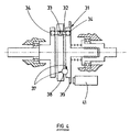
- the drive member 28 is coupled to first and second intermediate drive members 29, 30 through a plurality of "dog bone” differential drive arrangements 31 (only one of which is illustrated).
- the dog bone differential drive arrangements 31 comprise drive rods 32 which are pivotally mounted to the drive member 28 by means of spherical members 33 through which the rods 32 extend, the members 33 being located within bores formed in the drive member 28.
- the ends of the rods 32 are provided with similar spherical members 34 which are received within corresponding bores provided in the intermediate drive members 29, 30.
- the dog bone differential drive arrangements 31 are arranged to transmit angular movement of the drive member 28 to the intermediate drive members 29, 30 but to allow a limited amount of relative movement to occur between the intermediate drive members 29, 30, such movement being permitted by the rods 32 pivoting relative to the drive member 28.
- Only a single dog bone differential drive arrangement 31 is illustrated in Figures 3 and 4, it will be appreciated that several such arrangements may be provided, if desired, and it is envisaged to provide three such arrangements in the rotary actuator.
- the first intermediate drive member 29 is connected to the first output member 10 through a spline arrangement such that angular movement of the first intermediate drive member 29 is transmitted to the first output member 10.
- the second intermediate drive member 30 is connected to the second output member 11 through a ball spline arrangement 35 such that angular movement of the second intermediate drive member 30 is transmitted to the second output member 11.
- the ball spline arrangement 35 is arranged such that although relative angular movement is not permitted between the second intermediate drive member 30 and the second output member 11, relative axial movement between these components is permitted.
- a spring 36 is located between the second output member 11 and the second intermediate drive member 30 to bias the second intermediate drive member 30 towards the drive member 28.
- the drive member 28 and the second intermediate drive member 30 are provided with recesses 37 within which a spherical member 38 is received.
- the recesses 37 and spherical member 38 together form a ball and ramp arrangement arranged such that, in normal use, when the first and second output members 10, 11 rotate at the same speed as each other and the drive member 28, the spring 36 holds the second intermediate drive member 30 in the position illustrated in Figure 3.
- the second intermediate drive member 30 moves relative to the drive member 28 and the spherical member 38 will ride out of the recesses 37, forcing the second intermediate drive member 30 away from the drive member 28 against the action of the spring 36.
- the movement of the second intermediate drive member 30 causes an annular target member 39 which is biased by means of a spring 40 into engagement with the second intermediate drive member 30 to move, the movement of the target member 39 being detected by a position sensor 41.
- the size of the spring loading applied by the spring 36 to the ball and ramp arrangement can be selected in such a manner as to avoid the generation of fault signals where the difference in the loads on the output members 10, 11 is lower than a predetermined limit, thus avoiding the generation of nuisance fault signals, and allowing the mechanism to be tuned to take into account small permanent differential loads which may exist in certain arrangements or applications.
- the output signal from the position sensor 41 could be supplied to a control unit independently of the output signals of the position sensors associated with the other rotary actuators 4 of the flap system illustrated in Figure 1, it will be appreciated that the sensors 41 could be connected to one another in series, thus providing a fail safe arrangement in which the whole of the leading edge flap system can be shutdown in response to the presence of a fault in any part of that system.
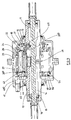
- the input member 14 drives a gear 17 a which meshes with gears 18 supported for rotation by means of the bearings 19.
- the end parts of the planet gear arrangement 24 driving first and second annular members 26, 27 which, in turn, cooperate with the drive parts 28 a , 28 b of the drive member 28.
- the drive part 28 b is provided with a plurality of recesses 42, each of which receives one end of a detent member 44, the other end of each detent member 44 engaging a plate member 46.
- the output member 10 carries an annular member 48, the member 48 being provided with slots through which the detent members 44 extend.
- the plate member 46 is secured to the annular member 48 such that the plate member is rotatable with the output member 10.
- the drive part 28 b of the drive member 28 includes a flange which is provided with a plurality of apertures 50 (as shown in Figure 6), each of which receives a respective roller member 52.
- the roller members 52 are engaged between ramped detents or recesses 57 in the outer periphery of the annular member 48 and the inner surface of the C-spring arrangement 54 such that the C-spring arrangement 54 serves to urge the roller members 52, and hence the annular member 48, towards a position in which the detent members 44 are seated within the recesses 42.
- the C-spring arrangement 54 comprises a plurality of C-springs.
- a circlip 56 is arranged to maintain the C-spring arrangement 54 in a fixed position relative to the annular member 48.
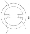
- the plate member 46 is of disc-like form and the inner surface comprises two inwardly extending regions 60 which are secured to the annular member 48.
- the surface of the drive part 28 a is preferably shaped to cooperate with an inner region 48 a of the annular member 48 so as to limit the extent of relative movement between the drive member 28 and the member 48.
- the rotary actuator and actuator system are described in relation to a leading edge flap arrangement or system, it will be appreciated that the actuator and actuator system are suitable for use in other aerospace applications in which a flap, hatch or door must be moved. Further, although the description is of an arrangement in which arms or levers are moved by the actuator, the invention is also applicable to arrangements in which the actuator drives a rack and pinion drive. Also, the skew sensing mechanism can be employed in units other than rotary actuators, for example in power drive units.
Landscapes
- Engineering & Computer Science (AREA)
- Aviation & Aerospace Engineering (AREA)
- Transmission Devices (AREA)
- Connection Of Motors, Electrical Generators, Mechanical Devices, And The Like (AREA)
Abstract
Description
- This invention relates to a rotary actuator and system. The invention is particularly suitable for use in aerospace applications, for example for use in moving the flaps, hatches or doors of an aircraft.
- In a typical actuator system for a flap of an aircraft, for example one of the high lift leading edge flaps, a pair of rotary actuators are driven by a common drive shaft, the actuators being connected to respective levers or arms mounted adjacent opposite ends or edges of the flap. Where a plurality of flaps are to be moved in unison, the actuators associated with each flap may be driven by a common drive shaft. The provision of two rotary actuators associated with each flap results in the actuator system being heavy. It is an object of the invention to provide an actuator system of reduced weight. It is a further object of the invention to provide an actuator suitable for use in such an actuator system which permits the detection of a fault indicative of a skew condition, and to provide a skew detection system suitable for use with other actuator systems.
- According to a first aspect of the invention there is provided an actuator system comprising a rotary actuator having an input, a first output, and a second output, the first and second outputs being arranged to move at substantially the same angular speed upon rotation of the input, a drive shaft coupled to the input, and first and second output shafts coupled, respectively, to the first and second outputs.
- The first and second output shafts may be coupled, in use, to respective arms or levers associated with opposite edges of a flap.
- Such an actuator system is advantageous in that a single rotary actuator is associated with each flap. As a result, the actuator system is of reduced weight.
- The first and second output shafts conveniently comprise torque tubes. The drive shaft conveniently extends through at least one of the torque tubes.
- According to a second aspect of the invention there is provided a rotary actuator comprising an input, a drive member angularly moveable within a housing in response to rotation of the input, first and second angularly moveable outputs, and a drive arrangement for transmitting movement of the drive member to the first and second outputs.
- The drive arrangement conveniently comprises a differential drive arrangement permitting limited relative angular movement of the first and second outputs. The differential drive arrangement conveniently comprises a "dog bone" differential drive arrangement.
- Preferably, the rotary actuator further comprises a detection arrangement arranged to produce an output signal in the event that relative angular movement occurs between the first and second outputs.
- The second output may include a member spring biased towards the drive member, the detector arrangement including a ball/ramp arrangement arranged to drive the said member of the second output against the action of the spring biasing in the event of relative angular movement occurring between the first and second outputs, and a position sensor arranged to monitor the position of the said member.
- Where such an arrangement is used to move an aircraft flap, in the event of a skew condition arising, relative angular movement will occur between the first and second outputs, and as a result the said member will move, the movement being detected by the position sensor which generates a signal indicative of the presence of a skew condition.
- In an alternative embodiment, one of the output shafts may carry an annular member, the detection arrangement including a C-spring arrangement arranged to act on the annular member. The drive member of the rotary actuator may be provided with at least one aperture for receiving a roller member, the roller member being engaged between the C-spring arrangement and the annular member. The C-spring arrangement may include a plurality of C-springs.
- The detection arrangement may comprise at least one detent member received within a recess provided in the drive member and engaging a surface of the plate member, the detection arrangement being arranged such that, in the event of relative angular movement between the first and second outputs, relative movement between the annular member and the drive member causes the detent member to ride out of the recess, thereby causing movement of the plate member.
- A position sensor may be employed to sense the position of the plate member. In the event of a skew condition arising, relative angular movement will occur between the first and second outputs, and as a result the plate member will move, the movement being detected by the position sensor which generates a signal indicative of the presence of a skew condition.
- According to another aspect of the invention there is provided a detection arrangement for use with a rotary actuator as described herein, the detection arrangement comprising first and second angularly moveable members, a ball and ramp arrangement arranged such that, upon relative angular movement occurring between the first and second members, one of the first and second members moves axially, and a position sensor arranged to provide an output signal in the event that axial movement of the said one of the first and second members is detected.
- According to another aspect of the invention, there is provided a detection arrangement for use with a rotary actuator as herein described, the detection arrangement comprising first and second angularly moveable members and a plate member arranged such that, upon relative angular movement occurring between the first and second members, the plate member is caused to move, a position sensor being arranged to provide an output signal in the event that movement of the plate member is detected.
- In each case, the first and second members of the detection arrangement may be coupled to one another by a differential drive arrangement, for example a dog bone differential drive arrangement.
- The invention will further be described, by way of example, with reference to the accompanying drawings, in which:-
- Figures 1 and 1a are diagrammatic views illustrating the actuator systems for a leading edge flap system;
- Figure 2 is a view similar to Figure 1a illustrating one of the systems in greater detail;
- Figure 3 is a sectional view of the actuator of the system of Figure 2;
- Figure 4 is a diagram illustrating operation of the skew sensing mechanism used in the actuator of Figure 3;
- Figure 5 is a sectional view of an alternative embodiment of an actuator to that shown in Figure 3;
- Figure 6 is a perspective view of a roller member forming part of the actuator in Figure 5; and
- Figure 7 is a plan view of a plate member forming part of the actuator in Figure 5.
-
- Figure 1 illustrates a leading edge high lift flap system for use with an aircraft. As illustrated, the system comprises a plurality of flaps 1 which are pivotally mounted upon an aircraft wing. Each flap 1 has associated therewith a pair of
lever arms 2 which are pivotally mounted upon the aircraft wing, thearms 2 cooperating with the flap 1 such that pivotal movement of thearms 2 causes the flap 1 to move relative to the wing. As illustrated in Figure 2, eacharm 2 is mounted for pivotal movement relative to the wing by means ofbearings 3. Thearms 2 are arranged to be driven, in use, by a rotary actuator 4, the actuator 4 having a pair of outputs, each output having connected thereto, a carbon fibre reinforced plastic high torque lowspeed torque tube 5, the end of which remote from the actuator 4 is secured to an input of a respective one of thearms 2 to drive thearms 2 for pivotal movement relative to the wing. - The rotary actuator 4 includes an input which is driven, in use, by a
drive shaft 6. As illustrated in Figure 1, thedrive shaft 6 is common to a plurality of flaps 1 and is arranged to be driven by a power drive unit 7 under the control of an appropriate control arrangement. The power drive unit 7 is located approximately half way along the length of thedrive shaft 6, and the ends of thedrive shaft 6 have associated therewith aposition sensor 8 which is arranged to detect rotational movement of the ends of thedrive shaft 6, thus permitting detection of the failure of the drive shaft between the power drive unit 7 and thesensor 8. As illustrated in Figures 1a and 2, thedrive shaft 6 extends substantially coaxially with thetorque tubes 5, thedrive shaft 6 extending through thetorque tubes 5. Although thedrive shaft 6 has been described, hereinbefore, as being a single integer or component, it will be appreciated that, if desired, thedrive shaft 6 may be made up of several components, each component extending between adjacent ones of the rotary actuators 4. - It will be appreciated that by providing a single rotary actuator 4 associated with each flap 1 rather than providing a separate rotary actuator associated with each of the
arms 2 associated with the flap, the number of actuators present in the leading edge flap system may be reduced, and as a result, the weight of the system can be reduced. - Figure 3 is a sectional view of the rotary actuator 4 illustrated in Figures 1, 1a and 2. The rotary actuator 4 comprises a two-part housing 9a, 9b having first and
second output members Bearings 12 are provided to rotatably mount theoutput members seal arrangements 13 are provided between the housing parts 9a, 9b and the first andsecond output members second outlet members input member 14,bearings 15 supporting theinput member 14 for rotation relative to the first andsecond output members Appropriate seals 16 are also provided between theinput member 14 and theoutput members - The
input member 14 protrudes from both the first andsecond output members input member 14 being shaped to form connectors whereby the component parts forming thedrive shaft 6 can be secured to theinput member 14 to drive theinput member 14 for rotation relative to the housing parts 9a, 9b. Theinput member 14 is shaped to define anintegral gear 17 which meshes withgears 18 mounted upon a carrier 18a located within thehousing 9 defined by the housing parts 9a, 9b, thegears 18 being supported for rotation upon the carrier 18a by means ofsuitable bearings 19. As illustrated in Figure 3, thegears 18 extend throughslots 20 formed in thefirst output member 10. As, in use, the first andsecond output members gears 18 through theslots 20 formed in thefirst output member 10 does not serve to limit the range through which thefirst output member 10 will be moved, in use. - The
gears 18 form the input of an epicyclic gear reduction arrangement including agear 21 which meshes with part of each of thegears 18, thegear 21 meshing with a series oflinkage members 22 which, in turn, drive asun gear 23. Thesun gear 23 drives a compoundplanet gear arrangement 24, a central part of which meshes with anannular gear 25 secured to thehousing 9. The end parts of theplanet gear arrangement 24 drive first and secondannular members parts 28a, 28b of adrive member 28 upon which thelinkage members 22 are mounted. The end parts of the compoundplanet gear arrangement 24 are provided with one fewer teeth than the central part thereof, thus for each complete rotation of theplanet gear arrangement 24, theannular members drive member 28 are moved relative to thehousing 9 through a distance equivalent to the width of one tooth of thegear 25. - The
drive member 28 is coupled to first and secondintermediate drive members differential drive arrangements 31 comprisedrive rods 32 which are pivotally mounted to thedrive member 28 by means ofspherical members 33 through which therods 32 extend, themembers 33 being located within bores formed in thedrive member 28. The ends of therods 32 are provided with similarspherical members 34 which are received within corresponding bores provided in theintermediate drive members differential drive arrangements 31 are arranged to transmit angular movement of thedrive member 28 to theintermediate drive members intermediate drive members rods 32 pivoting relative to thedrive member 28. Although only a single dog bonedifferential drive arrangement 31 is illustrated in Figures 3 and 4, it will be appreciated that several such arrangements may be provided, if desired, and it is envisaged to provide three such arrangements in the rotary actuator. - The first
intermediate drive member 29 is connected to thefirst output member 10 through a spline arrangement such that angular movement of the firstintermediate drive member 29 is transmitted to thefirst output member 10. The secondintermediate drive member 30 is connected to thesecond output member 11 through aball spline arrangement 35 such that angular movement of the secondintermediate drive member 30 is transmitted to thesecond output member 11. Theball spline arrangement 35 is arranged such that although relative angular movement is not permitted between the secondintermediate drive member 30 and thesecond output member 11, relative axial movement between these components is permitted. Aspring 36 is located between thesecond output member 11 and the secondintermediate drive member 30 to bias the secondintermediate drive member 30 towards thedrive member 28. - The
drive member 28 and the secondintermediate drive member 30 are provided withrecesses 37 within which aspherical member 38 is received. Therecesses 37 andspherical member 38 together form a ball and ramp arrangement arranged such that, in normal use, when the first andsecond output members drive member 28, thespring 36 holds the secondintermediate drive member 30 in the position illustrated in Figure 3. However, in the event that relative movement occurs between the first andsecond output members differential drive arrangements 31, the secondintermediate drive member 30 moves relative to thedrive member 28 and thespherical member 38 will ride out of therecesses 37, forcing the secondintermediate drive member 30 away from thedrive member 28 against the action of thespring 36. The movement of the secondintermediate drive member 30 causes anannular target member 39 which is biased by means of aspring 40 into engagement with the secondintermediate drive member 30 to move, the movement of thetarget member 39 being detected by aposition sensor 41. - In use, with the
input member 14 connected to an appropriate component of thedrive shaft 6 and with the first andsecond output members respective torque tubes 5, rotation of thedrive shaft 6 causes theinput member 14 to rotate, the rotation of theinput member 14 causing movement of the various gears to cause angular movement of thedrive member 28. The angular movement of thedrive member 28 is transmitted through the dog bonedifferential drive arrangements 31 to the first and secondintermediate drive members intermediate drive members second output members levers 2 and the flap 1 with which the rotary actuator 4 is associated. - In the event that one of the
levers 2 becomes jammed or disconnects, different loads will be presented to theoutput members spring 36 and the ball and ramp arrangement, relative movement will occur between the first andsecond output members drive member 28. The relative movement between thedrive member 28 and the secondintermediate drive member 30 results in thespherical member 38 riding out of therecesses 37, forcing the secondintermediate drive member 30 away from thedrive member 28 against the action of thespring 36. As described hereinbefore, such movement causes thetarget 39 to move, and the movement of thetarget 39 is sensed by theposition sensor 41. Theposition sensor 41 then provides an output signal indicative of the presence of a fault condition which is or could result in the generation of a skew condition. Upon the generation of such a signal, the system can be controlled in such a manner as to minimise the effect of the skew condition and the aircraft pilot can be alerted to the presence of the condition and compensate accordingly. - The size of the spring loading applied by the
spring 36 to the ball and ramp arrangement can be selected in such a manner as to avoid the generation of fault signals where the difference in the loads on theoutput members - Although the output signal from the
position sensor 41 could be supplied to a control unit independently of the output signals of the position sensors associated with the other rotary actuators 4 of the flap system illustrated in Figure 1, it will be appreciated that thesensors 41 could be connected to one another in series, thus providing a fail safe arrangement in which the whole of the leading edge flap system can be shutdown in response to the presence of a fault in any part of that system. - In order to ensure the actuator functions correctly in circumstances in which the differential load across the
output members spring 36 must provide a relatively large biasing force. In order to remove the need for a large spring, an alternative arrangement may be employed, as shown in Figure 5, in which similar parts to those shown in Figures 1 to 4 are referred to with like reference numerals. - Referring to Figures 5 to 7, the
input member 14 drives a gear 17a which meshes withgears 18 supported for rotation by means of thebearings 19. As in the embodiment shown in Figure 3, the end parts of theplanet gear arrangement 24 driving first and secondannular members drive parts 28a, 28b of thedrive member 28. - The
drive part 28b is provided with a plurality ofrecesses 42, each of which receives one end of adetent member 44, the other end of eachdetent member 44 engaging aplate member 46. Theoutput member 10 carries anannular member 48, themember 48 being provided with slots through which thedetent members 44 extend. Theplate member 46 is secured to theannular member 48 such that the plate member is rotatable with theoutput member 10. - The
drive part 28b of thedrive member 28 includes a flange which is provided with a plurality of apertures 50 (as shown in Figure 6), each of which receives arespective roller member 52. Theroller members 52 are engaged between ramped detents or recesses 57 in the outer periphery of theannular member 48 and the inner surface of the C-spring arrangement 54 such that the C-spring arrangement 54 serves to urge theroller members 52, and hence theannular member 48, towards a position in which thedetent members 44 are seated within therecesses 42. Typically, the C-spring arrangement 54 comprises a plurality of C-springs. Acirclip 56 is arranged to maintain the C-spring arrangement 54 in a fixed position relative to theannular member 48. As can be seen most clearly in Figure 7, theplate member 46 is of disc-like form and the inner surface comprises two inwardly extendingregions 60 which are secured to theannular member 48. - In use, with the
input member 14 connected to an appropriate component of thedrive shaft 6 and with the first andsecond output members drive shaft 6 causes theinput member 14 to rotate, the rotation of theinput member 14 causing movement of the various gears to cause angular movement of thedrive member 28 and, hence, driving movement of thelevers 2 and the flap with which the actuator is associated, as described previously. - In the event that one of the levers becomes jammed or disconnects, different loads will be presented to the
output members output members spring arrangement 54 acting on theroller members 52, theroller members 52 will be caused to move in a radially outward direction within theirrespective apertures 50, thereby permitting relative movement between theannular member 48 and thedrive member 28. Such relative movement between theannular member 48 and thedrive member 28 causes thedetent members 44 to ride out of theirrespective recesses 42. As thedetent members 44 engage theplate member 46, and as theregions 60 of theplate member 46 are secured to theoutput member 10, movement of thedetent members 44 out of therecesses 42 will cause theplate member 46 to bend. Bending movement of theplate member 46 is sensed by means of theposition sensor 41 and theposition sensor 41 provides an output signal indicative of the presence of a fault condition which is, or could result in, the generation of a skew condition. - The surface of the drive part 28a is preferably shaped to cooperate with an inner region 48a of the
annular member 48 so as to limit the extent of relative movement between thedrive member 28 and themember 48. - Although in the description hereinbefore, the rotary actuator and actuator system are described in relation to a leading edge flap arrangement or system, it will be appreciated that the actuator and actuator system are suitable for use in other aerospace applications in which a flap, hatch or door must be moved. Further, although the description is of an arrangement in which arms or levers are moved by the actuator, the invention is also applicable to arrangements in which the actuator drives a rack and pinion drive. Also, the skew sensing mechanism can be employed in units other than rotary actuators, for example in power drive units.
Claims (18)
- An actuator system comprising a rotary actuator (4) having an input member (14), a first output (29) and a second output (30), the first and second outputs (29, 30) being arranged to move at substantially the same angular speed upon rotation of the input member (14), a drive shaft (6) coupled to the input (14), and first and second output shafts (10, 11) coupled, respectively, to the first and second outputs (29, 30).
- The actuator system as claimed in Claim 1, wherein the first and second output shafts (10, 11) are coupled, in use, to respective levers (2) associated with opposite edges of a flap (1).
- The actuator system as claimed in Claim 1 or Claim 2, wherein the first and second output shafts (10, 11) each comprise a torque tube (5).
- The actuator system as claimed in Claim 3, wherein the drive shaft (6) extends through at least one of the torque tubes (5).
- A rotary actuator for use in the actuator system as claimed in any of Claims 1 to 4, comprising a drive member (28) angularly moveable within a housing (9) in response to rotation of the input (14) and a drive arrangement (31) for transmitting movement of the drive member (28) to the first and second outputs (29, 30).
- The rotary actuator as claimed in Claim 5, wherein the drive arrangement comprises a differential drive arrangement (31) permitting limited relative angular movement of the first and second outputs (29, 30).
- The rotary actuator as claimed in Claim 6, wherein the differential drive arrangement comprises a dog bone differential drive arrangement.
- The rotary actuator as claimed in any of Claims 5 to 7, further comprising a detection arrangement (36, 37, 38, 41; 44, 46, 52, 54, 41) arranged to produce an output signal in the event of relative angular movement between the first and second outputs (29, 30).
- The rotary actuator as claimed in Claim 8, wherein the second output includes a member (30) biased towards the drive member (28) by spring means (36), the detection arrangement (36, 37, 38, 41) being arranged to drive the member (30) of the second output against the action of the spring means (36) in the event of relative angular movement between the first and second outputs (29, 30).
- The rotary actuator as claimed in Claim 9, wherein the detection arrangement includes a ball/ramp arrangement (37, 38).
- The rotary actuator as claimed in Claim 9 or Claim 10, wherein the detection arrangement includes a position sensor (41) arranged to monitor the position of the member (30).
- The rotary actuator as claimed in Claim 8, wherein one of the output shafts (10, 11) carries an annular member (48), the detection arrangement including a C-spring arrangement (54) arranged to act on the annular member (48).
- The rotary actuator as claimed in Claim 12, wherein the drive member (28) is provided with an aperture (50) for receiving a roller member (52), the roller member (52) being engaged between the C-spring arrangement (54) and the annular member (48).
- The rotary actuator as claimed in Claim 13, wherein the detection arrangement comprises a detent member (44), one end of which is received within a recess (42) provided in the drive member (28) and the other end of which engages a surface of the plate member (46), the detection arrangement being arranged such that, in the event of relative angular movement between the first and second outputs (29, 30), relative movement between the annular member (48) and the drive member (28) causes the detent member (44) to ride out of the recess (42), thereby causing movement of the plate member (46).
- The rotary actuator as claimed in Claim 14, wherein the drive member (28) is shaped to cooperate with a region (48a) of the annular member (48) so as to limit the extent of relative movement between the drive member (28) and the annular member (48).
- The rotary actuator as claimed in Claim 14 or Claim 15, wherein the detection arrangement includes a position sensor (41) arranged to monitor the position of the plate member (46).
- A detection arrangement for use with a rotary actuator as claimed in any of Claims 5 to 11, the detection arrangement comprising first and second angularly moveable members (29, 30), a ball and ramp arrangement (37, 38) arranged such that, upon relative angular movement occurring between the first and second members (29, 30), one of the first and second members moves axially, and a position sensor (41) arranged to provide an output signal in the event that axial movement of the said one of the first and second members is detected.
- A detection arrangement for use with a rotary actuator as claimed in any of Claims 5 to 11, the detection arrangement comprising first and second angularly moveable members (29, 30) and a plate member (46) arranged such that, upon relative angular movement occurring between the first and second members (29, 30), the plate member (46) is caused to move, and a position sensor (41) arranged to provide an output signal in the event that movement of the plate member (46) is detected.
Applications Claiming Priority (2)
| Application Number | Priority Date | Filing Date | Title |
|---|---|---|---|
| GB9911049 | 1999-05-12 | ||
| GBGB9911049.6A GB9911049D0 (en) | 1999-05-12 | 1999-05-12 | Rotary actuator and system |
Publications (2)
| Publication Number | Publication Date |
|---|---|
| EP1052168A2 true EP1052168A2 (en) | 2000-11-15 |
| EP1052168A3 EP1052168A3 (en) | 2001-10-04 |
Family
ID=10853341
Family Applications (1)
| Application Number | Title | Priority Date | Filing Date |
|---|---|---|---|
| EP00303976A Withdrawn EP1052168A3 (en) | 1999-05-12 | 2000-05-11 | Rotary actuator and system |
Country Status (3)
| Country | Link |
|---|---|
| US (1) | US6443034B1 (en) |
| EP (1) | EP1052168A3 (en) |
| GB (1) | GB9911049D0 (en) |
Cited By (6)
| Publication number | Priority date | Publication date | Assignee | Title |
|---|---|---|---|---|
| EP1321359A3 (en) * | 2001-12-19 | 2004-09-08 | Moog Inc. | Differential torque limiter |
| EP2039605A3 (en) * | 2007-09-19 | 2011-05-25 | Liebherr-Aerospace Lindenberg GmbH | Aircraft high-lift device system with overload protection |
| WO2012045785A1 (en) * | 2010-10-05 | 2012-04-12 | Airbus Operations Gmbh | High lift system for an aircraft with a separate drive unit for each wing half |
| WO2012045796A1 (en) * | 2010-10-05 | 2012-04-12 | Airbus Operations Gmbh | High-lift system for a wing of an aircraft |
| EP2695810A1 (en) * | 2012-08-09 | 2014-02-12 | Airbus Operations GmbH | Drive system for control surfaces of an aircraft |
| DE102014207132B4 (en) | 2014-04-14 | 2020-06-18 | Zf Friedrichshafen Ag | Branch / differential gear |
Families Citing this family (13)
| Publication number | Priority date | Publication date | Assignee | Title |
|---|---|---|---|---|
| GB0126891D0 (en) * | 2001-11-08 | 2002-01-02 | Lucas Industries Ltd | Rotary actuator |
| US6705570B1 (en) * | 2003-04-14 | 2004-03-16 | Curtiss-Wright Controls, Inc. | Arrangement and associated system having an actuator and a tubular flap-drive member about the actuator |
| US7100870B2 (en) | 2003-10-15 | 2006-09-05 | Parker-Hannifin Corporation | Jam tolerant electromechanical actuation systems and methods of operation |
| DE102004047008A1 (en) * | 2004-09-28 | 2006-03-30 | Liebherr-Aerospace Lindenberg Gmbh | Device for adjusting aircraft altitude fins |
| GB0421568D0 (en) * | 2004-09-29 | 2004-10-27 | Smiths Group Plc | Drive assemblies |
| US8230750B2 (en) * | 2006-09-01 | 2012-07-31 | Parker-Hannifin Corporation | Electromechanical actuating assembly |
| US7641145B2 (en) * | 2006-11-21 | 2010-01-05 | Eaton Corporation | Apparatus for moving a control surface |
| US8136418B2 (en) * | 2007-02-07 | 2012-03-20 | Parker-Hannifin Corporation | Electromechanical actuating assembly |
| GB0705301D0 (en) | 2007-03-20 | 2007-04-25 | Goodrich Actuation Systems Ltd | Actuator arrangement |
| US8336818B2 (en) * | 2007-10-30 | 2012-12-25 | Parker-Hannifin Corporation | Jam tolerant electromechanical actuation systems and methods of operation |
| US8336817B2 (en) | 2007-10-30 | 2012-12-25 | Parker-Hannifin Corporation | Jam tolerant electromechanical actuation systems and methods of operation |
| US8281678B2 (en) | 2008-12-30 | 2012-10-09 | Eaton Corporation | Ballscrew assembly with detection feature |
| CA2808254C (en) * | 2010-08-20 | 2017-01-03 | Csir | A wing control system |
Family Cites Families (13)
| Publication number | Priority date | Publication date | Assignee | Title |
|---|---|---|---|---|
| US3935754A (en) * | 1974-06-14 | 1976-02-03 | The Boeing Company | Failure detector and indicator for aircraft flap actuation system |
| US4255946A (en) * | 1979-03-30 | 1981-03-17 | Hansen Quinten A | Torque overload sensing device |
| US4688744A (en) * | 1982-09-03 | 1987-08-25 | Sundstrand Corporation | Jam tolerant rotary actuation system |
| US4742730A (en) * | 1982-09-30 | 1988-05-10 | The Boeing Company | Failsafe rotary actuator |
| US4556131A (en) * | 1983-10-11 | 1985-12-03 | Sundstrand Corporation | Double output torque limiter |
| US4578993A (en) | 1983-12-30 | 1986-04-01 | Sundstrand Corporation | Failure detection system for geared rotary actuator mechanism |
| US4721016A (en) * | 1984-07-23 | 1988-01-26 | Sundstrand Corporation | Multiple-stage geared rotary actuator |
| US4779822A (en) | 1986-05-23 | 1988-10-25 | Sundstrand Corporation | Actuator system |
| DE68908578T2 (en) * | 1988-02-06 | 1994-01-20 | Lucas Ind Plc | Rotary actuator with intermediate gear. |
| US5133698A (en) * | 1989-09-07 | 1992-07-28 | Sundstrand Corporation | Power driven actuator system |
| US5071397A (en) * | 1990-10-01 | 1991-12-10 | Sundstrand Corporation | Jam tolerant geared rotary actuator with automatic disconnect |
| US5518466A (en) * | 1994-11-29 | 1996-05-21 | Curtiss Wright Flight Systems Inc. | Jam-tolerant rotary actuator |
| US5779587A (en) * | 1996-08-30 | 1998-07-14 | Curtiss Wright Flight Systems, Inc. | Jam tolerant rotary actuator with shear pins and disengagement coupling |
-
1999
- 1999-05-12 GB GBGB9911049.6A patent/GB9911049D0/en not_active Ceased
-
2000
- 2000-05-10 US US09/568,030 patent/US6443034B1/en not_active Expired - Lifetime
- 2000-05-11 EP EP00303976A patent/EP1052168A3/en not_active Withdrawn
Non-Patent Citations (1)
| Title |
|---|
| None |
Cited By (13)
| Publication number | Priority date | Publication date | Assignee | Title |
|---|---|---|---|---|
| EP1321359A3 (en) * | 2001-12-19 | 2004-09-08 | Moog Inc. | Differential torque limiter |
| EP2039605A3 (en) * | 2007-09-19 | 2011-05-25 | Liebherr-Aerospace Lindenberg GmbH | Aircraft high-lift device system with overload protection |
| US8132763B2 (en) | 2007-09-19 | 2012-03-13 | Liebherr-Aerospace Lindenberg Gmbh | Aircraft highlift system |
| CN103153791B (en) * | 2010-10-05 | 2016-12-21 | 空中客车德国运营有限责任公司 | There is the aircraft high-lift system of the single driver element for each half wing |
| WO2012045785A1 (en) * | 2010-10-05 | 2012-04-12 | Airbus Operations Gmbh | High lift system for an aircraft with a separate drive unit for each wing half |
| WO2012045796A1 (en) * | 2010-10-05 | 2012-04-12 | Airbus Operations Gmbh | High-lift system for a wing of an aircraft |
| CN103153791A (en) * | 2010-10-05 | 2013-06-12 | 空中客车德国运营有限责任公司 | High lift system for an aircraft with a separate drive unit for each wing half |
| US9682769B2 (en) | 2010-10-05 | 2017-06-20 | Airbus Operations Gmbh | High lift system for an aircraft with two separate drive units |
| EP2695810A1 (en) * | 2012-08-09 | 2014-02-12 | Airbus Operations GmbH | Drive system for control surfaces of an aircraft |
| CN104309798B (en) * | 2012-08-09 | 2016-10-05 | 空中客车德国运营有限责任公司 | The drive system controlling surface for aircraft |
| US9434469B2 (en) | 2012-08-09 | 2016-09-06 | Airbus Operations Gmbh | Drive system for control surfaces of an aircraft |
| CN104309798A (en) * | 2012-08-09 | 2015-01-28 | 空中客车德国运营有限责任公司 | Drive system for control surfaces of an aircraft |
| DE102014207132B4 (en) | 2014-04-14 | 2020-06-18 | Zf Friedrichshafen Ag | Branch / differential gear |
Also Published As
| Publication number | Publication date |
|---|---|
| GB9911049D0 (en) | 1999-07-14 |
| US6443034B1 (en) | 2002-09-03 |
| EP1052168A3 (en) | 2001-10-04 |
Similar Documents
| Publication | Publication Date | Title |
|---|---|---|
| US6443034B1 (en) | Rotary actuator and system | |
| US4578993A (en) | Failure detection system for geared rotary actuator mechanism | |
| US4779822A (en) | Actuator system | |
| US7410132B1 (en) | Jam tolerant electromechanical actuation systems and methods of operation | |
| US8336817B2 (en) | Jam tolerant electromechanical actuation systems and methods of operation | |
| US8336818B2 (en) | Jam tolerant electromechanical actuation systems and methods of operation | |
| US9376204B2 (en) | High-lift system for a wing of an aircraft | |
| JP6835855B2 (en) | Synthetic and fault tolerant rotary actuator assembly | |
| EP0325027A1 (en) | Fail-free actuator assembly | |
| EP2783135B1 (en) | An electromechanical actuator for an aircraft control surface, and an aircraft provided with such an actuator | |
| US9470272B2 (en) | Torque limiter responsive to output torque | |
| EP2280194B1 (en) | Rotary actuator | |
| EP1088753A2 (en) | Skew detection system | |
| WO2014041143A1 (en) | An electromechanical actuator with anti-blocking means | |
| EP1321359B1 (en) | Differential torque limiter | |
| CN104139850B (en) | Drive system for a high lift system of an aircraft and method for detecting a misalignment between a transmission shaft and an opening in a drive system for a high lift system of an aircraft | |
| WO2005024273A1 (en) | Apparatus for releasing a jam in a lead screw actuator | |
| EP4097831B1 (en) | Fault tolerant multiple rotary actuator assembly | |
| CN111692326B (en) | Driving device, robot, and image forming apparatus | |
| EP0141609B1 (en) | Device for limiting output force applied by a rotary transmission | |
| GB2190165A (en) | Shaft relative speed limiting system | |
| US6616096B1 (en) | Failsafe arrangement | |
| US4712449A (en) | Apparatus for limiting differential rotation |
Legal Events
| Date | Code | Title | Description |
|---|---|---|---|
| PUAI | Public reference made under article 153(3) epc to a published international application that has entered the european phase |
Free format text: ORIGINAL CODE: 0009012 |
|
| AK | Designated contracting states |
Kind code of ref document: A2 Designated state(s): AT BE CH CY DE DK ES FI FR GB GR IE IT LI LU MC NL PT SE Kind code of ref document: A2 Designated state(s): DE ES FR GB IT |
|
| AX | Request for extension of the european patent |
Free format text: AL;LT;LV;MK;RO;SI |
|
| PUAL | Search report despatched |
Free format text: ORIGINAL CODE: 0009013 |
|
| AK | Designated contracting states |
Kind code of ref document: A3 Designated state(s): AT BE CH CY DE DK ES FI FR GB GR IE IT LI LU MC NL PT SE |
|
| AX | Request for extension of the european patent |
Free format text: AL;LT;LV;MK;RO;SI |
|
| RAP1 | Party data changed (applicant data changed or rights of an application transferred) |
Owner name: LUCAS INDUSTRIES LIMITED |
|
| 17P | Request for examination filed |
Effective date: 20020403 |
|
| AKX | Designation fees paid |
Free format text: DE ES FR GB IT |
|
| RAP1 | Party data changed (applicant data changed or rights of an application transferred) |
Owner name: GOODRICH ACTUATION SYSTEMS LTD |
|
| 17Q | First examination report despatched |
Effective date: 20040331 |
|
| GRAP | Despatch of communication of intention to grant a patent |
Free format text: ORIGINAL CODE: EPIDOSNIGR1 |
|
| STAA | Information on the status of an ep patent application or granted ep patent |
Free format text: STATUS: THE APPLICATION IS DEEMED TO BE WITHDRAWN |
|
| 18D | Application deemed to be withdrawn |
Effective date: 20050719 |