EP1052107A2 - Thermal printer - Google Patents
Thermal printer Download PDFInfo
- Publication number
- EP1052107A2 EP1052107A2 EP00303228A EP00303228A EP1052107A2 EP 1052107 A2 EP1052107 A2 EP 1052107A2 EP 00303228 A EP00303228 A EP 00303228A EP 00303228 A EP00303228 A EP 00303228A EP 1052107 A2 EP1052107 A2 EP 1052107A2
- Authority
- EP
- European Patent Office
- Prior art keywords
- platen roller
- lock arm
- bearing
- body frame
- thermal head
- Prior art date
- Legal status (The legal status is an assumption and is not a legal conclusion. Google has not performed a legal analysis and makes no representation as to the accuracy of the status listed.)
- Granted
Links
Images




Classifications
-
- B—PERFORMING OPERATIONS; TRANSPORTING
- B41—PRINTING; LINING MACHINES; TYPEWRITERS; STAMPS
- B41J—TYPEWRITERS; SELECTIVE PRINTING MECHANISMS, i.e. MECHANISMS PRINTING OTHERWISE THAN FROM A FORME; CORRECTION OF TYPOGRAPHICAL ERRORS
- B41J13/00—Devices or arrangements of selective printing mechanisms, e.g. ink-jet printers or thermal printers, specially adapted for supporting or handling copy material in short lengths, e.g. sheets
- B41J13/02—Rollers
- B41J13/025—Special roller holding or lifting means, e.g. for temporarily raising one roller of a pair of nipping rollers for inserting printing material
-
- B—PERFORMING OPERATIONS; TRANSPORTING
- B41—PRINTING; LINING MACHINES; TYPEWRITERS; STAMPS
- B41J—TYPEWRITERS; SELECTIVE PRINTING MECHANISMS, i.e. MECHANISMS PRINTING OTHERWISE THAN FROM A FORME; CORRECTION OF TYPOGRAPHICAL ERRORS
- B41J11/00—Devices or arrangements of selective printing mechanisms, e.g. ink-jet printers or thermal printers, for supporting or handling copy material in sheet or web form
- B41J11/02—Platens
- B41J11/04—Roller platens
Definitions
- the present invention relates to a printing apparatus and a mechanism for removably supporting a platen roller when a printer head is brought into press-contact with the platen roller to interpose printing paper between the printer head and the platen roller, and more particularly, the invention relates to a thermal printing apparatus (thermal printer) capable of enhancing operability for the loading of the printing paper, head cleaning and the like.
- a thermal printer is constituted to form an image on a thermal printing paper by using a thermal head.
- Fig. 8 shows an example of the structure of a conventional thermal printer and a printing paper inserting path.
- a platen roller 2 is rotatably supported to a body frame 1 through a bearing (not shown), and a thermal head 5 is rotated and biased to come in press-contact with the platen roller 2 by the biasing force of a pressure spring 8.
- the thermal head 5 can be separated from the platen roller 2 to form a clearance between the thermal head 5 and the platen roller 2 at the time of the loading of the printing paper, maintenance such as head cleaning, and the like.
- the printing paper is inserted in the clearance and is thus loaded.
- Fig. 9 is a side view illustrating a mechanism for removably supporting the platen roller which has a problem to be solved by the present invention.
- Fig. 9 shows an example of the structure of a mechanism for pushing a bearing 3 of the platen roller 2 against the body frame 1 by the pressing force of the thermal head 5, thereby engaging the platen roller 2.
- the platen roller 2 is provided across the body frame 1 of the printer rotatably and removably.
- a line type thermal head 5 fixed to the front face of a head support member 6 is biased to come in press-contact with the platen roller 2.
- the thermal head 5 is arranged almost vertically in the body frame 1.
- a portion 1c of the body frame 1 for engaging the platen roller 2 has the shape of a special slit in order to attach or remove the platen roller 2.
- the platen roller 2 can be completely attached to or removed from the body frame 1 as shown in Fig. 9.
- the platen roller 2 is lifted up from the body frame 1 and is separated therefrom, the printing paper is dropped into the printer body and the platen roller 2 is then attached to the body frame 1 again as shown in Fig. 9.
- printing paper is loaded between the thermal head 5 and the platen roller 2.
- the platen roller 2 is engaged with the frame 1 by the biasing force of the thermal head 5 pressing the platen roller 2.
- the structure has low positioning precision for the platen roller 2. Moreover, great operating force is required for the attachment and removal of the platen roller 2.
- the present invention is proposed in order to solve the above-mentioned problems, and an object of the present invention is to provide a platen roller support mechanism for a thermal printer which has high reliability for the attachment and removal of the platen roller 2 to and from the body frame 1, can easily load printing paper, and can achieve a reduction in size.
- the present invention according to claim 1 is directed to a line dot type thermal printer in which a lock arm carrying a bearing of a platen roller is provided and the bearing of the platen roller is sandwiched between a slit formed on a body frame and the lock arm by the biasing force applied to the lock arm. Consequently, the platen roller is supported in a predetermined position.
- the slit has such a shape as to guide the bearing of the platen roller to the predetermined position with respect to the frame.
- the biasing force applied to the lock arm is generated by using a pressure spring for causing the thermal head to come in press-contact with the platen roller.
- the present invention according to claim 2 is related to the shape of a slit of the frame into which the bearing of the platen roller slides and is characterized in that the slit having the shape of a slope is formed on the body frame in a direction in which the thermal head presses the platen roller.
- the thermal head presses the platen roller and lifts up the platen roller by using the slope. Consequently, the platen roller can be separated from the frame.
- the bearing of the platen roller is set to a predetermined position along the slope again by the biasing force.
- the present invention according to claim 3 is characterized in that the lock arm is provided with a cam face for causing the lock arm to further push up the bearing of the platen roller after the platen roller has been lifted up by the thermal head.
- the present invention according to claim 4 is characterized in that the operation of the lock arm is carried out by the cam supported to the body frame.
- an operating portion having various shapes such as a lever, light and reliable operation can be carried out.
- the present invention can be applied to a wide range of uses.
- the present invention according to claim 5 solves the problem related to the mechanism according to the present invention.
- the pressure spring is greatly deformed.
- a stopper for interfering with a head support member is provided on the lock arm.
- Fig. 1 is a partially sectional plan view showing an embodiment of the present invention
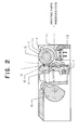
- Fig. 2 is a side view taken along the line A - A in Fig. 1
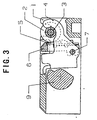
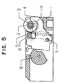
- Figs. 3 to 7 are side views taken along the line B - B in Fig. 1.
- These drawings are sectional views showing a main part in order to plainly illustrate the characteristic structure of a thermal printer according to the embodiment which will be described below.
- Fig. 2 to Fig. 7 are not sectional views but partially perspective and side views in order to easily represent the state in which a lock arm 4, a platen roller 2 and a thermal head 5 and a head support member 6 interact one another and to prevent the drawings from being complicated.
- the platen roller 2 is provided between side walls 1a and 1b of a body frame 1 of the printer.
- the body frame 1 is formed of plastic
- the platen roller 2 includes a shaft 2a and a friction roller 2b attached to the shaft 2a and formed of a cylindrical elastic member.
- the shaft 2a has both ends supported rotatably by a slit 1c shown in Fig. 2 which is formed on the side walls 1a and 1b of the body frame 1 and by bearings 3a and 3b of the platen roller 2 which are fitted in the lock arm 4 and are almost cylindrical.
- the slit 1c has such a shape as to guide the bearings 3a and 3b of the platen roller 2 in predetermined positions with respect to the frame.
- a rotatably driving motor (not shown) is fixedly attached to the side wall 1a of the body frame 1.
- the rotation motion of the rotatably driving motor is transmitted from a reduction gear 13, which is provided on the side wall 1a of the body frame 1 and which is partially shown, to a platen driving gear 11 attached to one of ends of the shaft 2a. Consequently, the platen roller 2 is driven and rotated.
- a guide face 1e for smoothly feeding a thermal paper as a printing paper is formed in the lower portion of the front end of the body frame 1.
- a printing paper detecting device 12 including a photointerrupter or the like is embedded in a part of the guide face 1e.
- the line dot type thermal head 5 is fixed to the front face of the head support member 6 and is arranged in parallel with the platen roller 2.
- the head support member 6 is attached to the lock arm 4 such that they can approach or separate from each other by using a support shaft 7 as the center of rotation.
- a pressure spring 8 is attached to bias the head support member 6 and the lock arm 4 to separate from each other.
- the pressure spring 8 gives biasing force for engaging the bearing 3 of the platen roller 2 between the lock arm 4 and the slit 1c of he body frame 1, and also serves as biasing force for causing the thermal head 5 to come in press-contact with the platen roller 2 as shown in Fig. 2 in the state in which the bearing 3 of the platen roller 2 is engaged between the slit 1c of the body frame 1 and the lock arm 4.
- a cam 9 for disengaging the bearing 3 of the platen roller 2 from the lock arm 4 and a lever 10 fixed to the cam 9 for operating the cam 9 are rotatably attached to the body frame 1.
- the platen roller can be supported with high positioning precision by means of the lock arm for biasing and carrying the bearing of the platen roller between the lock arm and the slit provided on the frame.
- the platen roller can be completely removed from the body frame by means of the slope provided on the slit of the frame and by means of the cam face provided on the lock arm. Consequently, the platen roller can be attached or removed with high reliability.
- the operation is carried out by means of the lever having high operability. Therefore, the printing paper can be loaded easily and operability can be enhanced for a paper jam, maintenance such as head cleaning and the like.
Landscapes
- Handling Of Sheets (AREA)
- Electronic Switches (AREA)
- Common Mechanisms (AREA)
Abstract
Description
Claims (5)
- A thermal printer comprising:a body frame (1);a line dot type thermal head (5) and a head support member (6) provided integrally with a back face thereof;a platen roller (2) provided in parallel with the thermal head (5); anda lock arm (4) for supporting a bearing (3) of the platen roller (2), the bearing (3) allowing the platen roller (2) to freely rotate,the thermal printer structured such that the bearing (3) of the platen roller (2) is carried by the lock arm (4) and a slit (1c) which has such a shape as to guide, into predetermined positions, the bearings (3a, 3b) of the platen roller (2) provided on side walls (1a, 1b) of the body frame (1), and that the lock arm (4) pushes the bearing (3) of the platen roller (2) against the frame (1) by utilizing biasing force of a pressure spring (8) for pressing the thermal head (5).
- A thermal printer according to claim 1, characterized in that the slit 1(c) of the body frame (1) is provided with a slope shape (1d) in a direction in which the thermal head (5) presses the platen roller (2), and in that the thermal head (5) pushes up the platen roller (2) by using the slope (1d) provided cm the slit (1c) of the frame (1) as the lock arm (4) is moved away.
- A thermal printer according to claim 1 or 2, characterized in that, when the lock arm (4) is returned by the biasing force of the pressure spring (8) after the thermal head (5) pushes up the platen roller (2), the bearing (3) of the platen roller (2) is further pushed upward to completely remove the platen roller (2) from the body frame (1) by a cam face (4a) formed on an edge of the lock arm (4).
- A thermal printer according to claim 1, 2, or 3, characterized in that the lock arm (4) is operated by the cam (9) integrated with a lever (10) provided outside the side walls (1a, 1b) of the body frame (1).
- A thermal printer according to claim 1, 2, or 3, characterized in that the lock arm (4) is provided with a stopper (4b) for interfering with the head support member (6) before the pressure spring (8) is excessively deformed even if the lever (10) is operated with the platen roller (2) depressed so as not to be removed.
Applications Claiming Priority (2)
| Application Number | Priority Date | Filing Date | Title |
|---|---|---|---|
| JP12897499 | 1999-05-10 | ||
| JP12897499A JP3599595B2 (en) | 1999-05-10 | 1999-05-10 | Thermal printer |
Publications (3)
| Publication Number | Publication Date |
|---|---|
| EP1052107A2 true EP1052107A2 (en) | 2000-11-15 |
| EP1052107A3 EP1052107A3 (en) | 2001-01-31 |
| EP1052107B1 EP1052107B1 (en) | 2006-05-24 |
Family
ID=14998019
Family Applications (1)
| Application Number | Title | Priority Date | Filing Date |
|---|---|---|---|
| EP00303228A Expired - Lifetime EP1052107B1 (en) | 1999-05-10 | 2000-04-17 | Thermal printer |
Country Status (4)
| Country | Link |
|---|---|
| US (1) | US6249302B1 (en) |
| EP (1) | EP1052107B1 (en) |
| JP (1) | JP3599595B2 (en) |
| DE (1) | DE60028121T2 (en) |
Cited By (8)
| Publication number | Priority date | Publication date | Assignee | Title |
|---|---|---|---|---|
| EP1323535A3 (en) * | 2001-12-28 | 2004-01-07 | Sii P & S Inc. | Thermal printer |
| EP1447227A1 (en) * | 2003-02-13 | 2004-08-18 | SII P & S Inc. | Thermally activating apparatus |
| EP1652682A1 (en) * | 2004-10-27 | 2006-05-03 | Fujitsu Component Limited | Thermal printer unit |
| EP1882595A1 (en) * | 2006-07-28 | 2008-01-30 | Alps Electric Co., Ltd. | Printer |
| EP1950046A3 (en) * | 2007-01-25 | 2009-05-20 | Seiko Instruments Inc. | Platen retaining structure and recording unit |
| WO2012058593A3 (en) * | 2010-10-28 | 2013-01-24 | Zih Corp. | Printer with printhead assembly, clutch assembly, and printer ribbon transport assembly |
| CN106313908A (en) * | 2016-08-22 | 2017-01-11 | 厦门顶尖电子有限公司 | Matching structure for rubber roller of thermal printer core and open bearing of main support |
| CN106660376A (en) * | 2014-07-07 | 2017-05-10 | 富士通电子零件有限公司 | Printer device |
Families Citing this family (40)
| Publication number | Priority date | Publication date | Assignee | Title |
|---|---|---|---|---|
| JP2002248820A (en) * | 2001-02-23 | 2002-09-03 | Japan Cbm Corp | Thermal printer |
| EP1262326B1 (en) * | 2001-05-22 | 2006-02-08 | Custom Engineering SpA | Thermal printer closing apparatus |
| JP2003200625A (en) * | 2001-10-23 | 2003-07-15 | Fujitsu Component Ltd | Thermal printer |
| JP3885564B2 (en) * | 2001-11-16 | 2007-02-21 | セイコーエプソン株式会社 | Printer and printer unit |
| US6664995B2 (en) | 2002-02-06 | 2003-12-16 | Brady Worldwide, Inc. | Label media-specific plotter cutter depth control |
| US6768502B2 (en) | 2002-02-06 | 2004-07-27 | Brady Worldwide, Inc. | Label printer dot line registration assembly |
| US6742858B2 (en) * | 2002-02-06 | 2004-06-01 | Brady Worldwide, Inc. | Label printer-cutter with mutually exclusive printing and cutting operations |
| US6616360B2 (en) | 2002-02-06 | 2003-09-09 | Brady Worldwide, Inc. | Label printer end and plotter cutting assembly |
| US6788324B2 (en) * | 2002-02-06 | 2004-09-07 | Brady Worldwide, Inc. | Encoder-based control of printhead firing in a label printer |
| US6860658B2 (en) | 2002-02-15 | 2005-03-01 | Brady Worldwide, Inc. | Ribbon wiper |
| JP4350350B2 (en) * | 2002-09-27 | 2009-10-21 | セイコーインスツル株式会社 | Thermal printer |
| JP4350942B2 (en) | 2002-12-18 | 2009-10-28 | 富士通コンポーネント株式会社 | Thermal printer |
| CN1301862C (en) * | 2003-04-29 | 2007-02-28 | 诚研科技股份有限公司 | Thermal printer with thermal printhead guide mechanism |
| JP4376816B2 (en) | 2005-03-17 | 2009-12-02 | セイコーインスツル株式会社 | Platen roller holding structure and recording apparatus |
| JP4595089B2 (en) * | 2005-04-19 | 2010-12-08 | ソニー株式会社 | Print positioning mechanism and printer |
| JP4817101B2 (en) * | 2005-09-12 | 2011-11-16 | セイコーインスツル株式会社 | Thermal activation device, printing device and printer |
| JP4273110B2 (en) * | 2005-09-14 | 2009-06-03 | Necインフロンティア株式会社 | Frame open mechanism and thermal printer |
| JP4704941B2 (en) * | 2006-03-23 | 2011-06-22 | セイコーインスツル株式会社 | Thermal printer |
| JP2007331112A (en) | 2006-06-12 | 2007-12-27 | Seiko Epson Corp | Thermal printer |
| JP2008030302A (en) * | 2006-07-28 | 2008-02-14 | Alps Electric Co Ltd | Printer |
| JP4761465B2 (en) * | 2006-09-15 | 2011-08-31 | セイコーインスツル株式会社 | Thermal printer |
| JP4827035B2 (en) | 2007-01-25 | 2011-11-30 | セイコーインスツル株式会社 | Platen holding mechanism and recording apparatus |
| JP5037289B2 (en) * | 2007-10-04 | 2012-09-26 | セイコーインスツル株式会社 | Thermal printer unit and printing device |
| JP2009143133A (en) | 2007-12-14 | 2009-07-02 | Seiko Instruments Inc | Thermal printer |
| JP5181145B2 (en) * | 2008-05-21 | 2013-04-10 | セイコーインスツル株式会社 | Thermal printer |
| JP2011073372A (en) | 2009-09-30 | 2011-04-14 | Seiko Instruments Inc | Thermal printer |
| JP2011110917A (en) * | 2009-11-30 | 2011-06-09 | Seiko Instruments Inc | Thermal printer |
| CN102001233B (en) * | 2010-09-10 | 2012-06-27 | 深圳市理邦精密仪器股份有限公司 | Printer structure |
| JP5823743B2 (en) * | 2011-06-22 | 2015-11-25 | 富士通コンポーネント株式会社 | Thermal printer |
| KR101656965B1 (en) | 2011-10-07 | 2016-09-12 | 후지쯔 콤포넌트 가부시끼가이샤 | Printer device |
| JP5865126B2 (en) | 2012-03-02 | 2016-02-17 | 富士通コンポーネント株式会社 | Printer device |
| JP6408834B2 (en) * | 2014-08-29 | 2018-10-17 | サトーホールディングス株式会社 | Platen unit and printer |
| US9604474B2 (en) | 2014-09-02 | 2017-03-28 | Seiko Instruments Inc. | Printing unit and printer |
| JP6422333B2 (en) * | 2014-09-02 | 2018-11-14 | セイコーインスツル株式会社 | Printing unit and printer |
| US9493017B2 (en) * | 2015-02-13 | 2016-11-15 | Zih Corp. | Modular print drive assembly and platen assembly |
| JP6431590B2 (en) * | 2017-12-05 | 2018-11-28 | サトーホールディングス株式会社 | printer |
| CN107901632A (en) * | 2017-12-26 | 2018-04-13 | 沃博思(厦门)电子科技有限公司 | A kind of self-opening closure of thermal printer cassette |
| US11400735B2 (en) | 2019-12-02 | 2022-08-02 | Seiko Instruments Inc. | Printing unit and thermal printer |
| CN112092509B (en) * | 2020-10-15 | 2025-03-21 | 珠海趣印科技有限公司 | A thermal printer pressing structure and use method thereof |
| JP7558859B2 (en) * | 2021-03-23 | 2024-10-01 | セイコーインスツル株式会社 | Printing unit and thermal printer |
Family Cites Families (5)
| Publication number | Priority date | Publication date | Assignee | Title |
|---|---|---|---|---|
| EP0386919A3 (en) * | 1989-03-06 | 1991-01-30 | Tokyo Electric Co., Ltd. | Thermal printer |
| JP2918287B2 (en) * | 1990-05-09 | 1999-07-12 | 株式会社リコー | Platen support device for printing press |
| JP3005916B2 (en) * | 1990-10-24 | 2000-02-07 | 株式会社リコー | Thermal recording device |
| FR2697776B1 (en) * | 1992-11-06 | 1995-03-03 | Axiohm | Opening thermal printing device. |
| JPH1148507A (en) * | 1997-07-30 | 1999-02-23 | Seiko Instr Inc | Line thermal printer |
-
1999
- 1999-05-10 JP JP12897499A patent/JP3599595B2/en not_active Expired - Fee Related
-
2000
- 2000-04-17 EP EP00303228A patent/EP1052107B1/en not_active Expired - Lifetime
- 2000-04-17 DE DE60028121T patent/DE60028121T2/en not_active Expired - Lifetime
- 2000-04-26 US US09/558,618 patent/US6249302B1/en not_active Expired - Lifetime
Cited By (15)
| Publication number | Priority date | Publication date | Assignee | Title |
|---|---|---|---|---|
| EP1323535A3 (en) * | 2001-12-28 | 2004-01-07 | Sii P & S Inc. | Thermal printer |
| EP1447227A1 (en) * | 2003-02-13 | 2004-08-18 | SII P & S Inc. | Thermally activating apparatus |
| US6975340B2 (en) | 2003-02-13 | 2005-12-13 | Seiko Instruments Inc. | Thermally activating apparatus |
| EP1652682A1 (en) * | 2004-10-27 | 2006-05-03 | Fujitsu Component Limited | Thermal printer unit |
| US8044987B2 (en) | 2006-07-28 | 2011-10-25 | Alps Electric Co., Ltd. | Printer with a print head urged to come into contact with a platen roller |
| EP1882595A1 (en) * | 2006-07-28 | 2008-01-30 | Alps Electric Co., Ltd. | Printer |
| EP1950046A3 (en) * | 2007-01-25 | 2009-05-20 | Seiko Instruments Inc. | Platen retaining structure and recording unit |
| WO2012058593A3 (en) * | 2010-10-28 | 2013-01-24 | Zih Corp. | Printer with printhead assembly, clutch assembly, and printer ribbon transport assembly |
| CN103442897A (en) * | 2010-10-28 | 2013-12-11 | Zih公司 | Printer with printhead assembly, clutch assembly, and printer ribbon transport assembly |
| US8882371B2 (en) | 2010-10-28 | 2014-11-11 | Zih Corp. | Printer with printhead assembly, clutch assembly, and printer ribbon transport assembly |
| CN103442897B (en) * | 2010-10-28 | 2015-09-30 | Zih公司 | There is the printer of print head assembly, clutch pack and printer color tape transport assembly |
| US9211705B2 (en) | 2010-10-28 | 2015-12-15 | Zih Corp. | Printer with printhead assembly, clutch assembly, and printer ribbon transport assembly |
| US10160239B2 (en) | 2010-10-28 | 2018-12-25 | Zih Corp. | Printer with printhead assembly, clutch assembly, and printer ribbon transport assembly |
| CN106660376A (en) * | 2014-07-07 | 2017-05-10 | 富士通电子零件有限公司 | Printer device |
| CN106313908A (en) * | 2016-08-22 | 2017-01-11 | 厦门顶尖电子有限公司 | Matching structure for rubber roller of thermal printer core and open bearing of main support |
Also Published As
| Publication number | Publication date |
|---|---|
| JP3599595B2 (en) | 2004-12-08 |
| JP2000318260A (en) | 2000-11-21 |
| EP1052107A3 (en) | 2001-01-31 |
| DE60028121D1 (en) | 2006-06-29 |
| EP1052107B1 (en) | 2006-05-24 |
| US6249302B1 (en) | 2001-06-19 |
| DE60028121T2 (en) | 2006-09-28 |
Similar Documents
| Publication | Publication Date | Title |
|---|---|---|
| EP1052107B1 (en) | Thermal printer | |
| US4999016A (en) | Hand recording apparatus | |
| JP4492125B2 (en) | Roll sheet holder and tape printer | |
| EP1024411B1 (en) | Method of detecting amount of remaining sheets of paper | |
| EP1479525A1 (en) | Thermal printer with load detection type sensor | |
| EP1323535A2 (en) | Thermal printer | |
| EP0894640A2 (en) | Printer apparatus | |
| JPS6343289B2 (en) | ||
| JPH0546925Y2 (en) | ||
| US4982946A (en) | Apparatus for transporting paper | |
| JPH10114091A (en) | Thermal printer | |
| JP3765397B2 (en) | Thermal transfer printer | |
| EP0884725B1 (en) | Magnetic recording/reproducing apparatus | |
| JP2000318257A (en) | Line thermal printer | |
| US7694952B2 (en) | Print media bin | |
| JPH1071757A (en) | Printing equipment | |
| JP3093658U (en) | Scanner printer | |
| JP2576471B2 (en) | Printer paper holding device | |
| KR100553871B1 (en) | Knock-up plate lifting device for printing equipment | |
| KR0124531Y1 (en) | Top Loading Device of Printer | |
| JP3519198B2 (en) | Cutter mechanism of tape printer | |
| JPH08208046A (en) | Sheet feeding apparatus and image forming apparatus | |
| JPH0215455B2 (en) | ||
| JP2001033871A (en) | Camera accessory attachment / detachment device | |
| JP3077896B2 (en) | Paper cassette |
Legal Events
| Date | Code | Title | Description |
|---|---|---|---|
| PUAI | Public reference made under article 153(3) epc to a published international application that has entered the european phase |
Free format text: ORIGINAL CODE: 0009012 |
|
| AK | Designated contracting states |
Kind code of ref document: A2 Designated state(s): DE FR GB IT |
|
| AX | Request for extension of the european patent |
Free format text: AL;LT;LV;MK;RO;SI |
|
| PUAL | Search report despatched |
Free format text: ORIGINAL CODE: 0009013 |
|
| AK | Designated contracting states |
Kind code of ref document: A3 Designated state(s): AT BE CH CY DE DK ES FI FR GB GR IE IT LI LU MC NL PT SE |
|
| AX | Request for extension of the european patent |
Free format text: AL;LT;LV;MK;RO;SI |
|
| 17P | Request for examination filed |
Effective date: 20010614 |
|
| AKX | Designation fees paid |
Free format text: DE FR GB IT |
|
| 17Q | First examination report despatched |
Effective date: 20040907 |
|
| GRAP | Despatch of communication of intention to grant a patent |
Free format text: ORIGINAL CODE: EPIDOSNIGR1 |
|
| GRAS | Grant fee paid |
Free format text: ORIGINAL CODE: EPIDOSNIGR3 |
|
| GRAA | (expected) grant |
Free format text: ORIGINAL CODE: 0009210 |
|
| AK | Designated contracting states |
Kind code of ref document: B1 Designated state(s): DE FR GB IT |
|
| PG25 | Lapsed in a contracting state [announced via postgrant information from national office to epo] |
Ref country code: IT Free format text: LAPSE BECAUSE OF FAILURE TO SUBMIT A TRANSLATION OF THE DESCRIPTION OR TO PAY THE FEE WITHIN THE PRESCRIBED TIME-LIMIT;WARNING: LAPSES OF ITALIAN PATENTS WITH EFFECTIVE DATE BEFORE 2007 MAY HAVE OCCURRED AT ANY TIME BEFORE 2007. THE CORRECT EFFECTIVE DATE MAY BE DIFFERENT FROM THE ONE RECORDED. Effective date: 20060524 |
|
| REG | Reference to a national code |
Ref country code: GB Ref legal event code: FG4D |
|
| REF | Corresponds to: |
Ref document number: 60028121 Country of ref document: DE Date of ref document: 20060629 Kind code of ref document: P |
|
| ET | Fr: translation filed | ||
| PLBE | No opposition filed within time limit |
Free format text: ORIGINAL CODE: 0009261 |
|
| STAA | Information on the status of an ep patent application or granted ep patent |
Free format text: STATUS: NO OPPOSITION FILED WITHIN TIME LIMIT |
|
| 26N | No opposition filed |
Effective date: 20070227 |
|
| REG | Reference to a national code |
Ref country code: FR Ref legal event code: PLFP Year of fee payment: 17 |
|
| PGFP | Annual fee paid to national office [announced via postgrant information from national office to epo] |
Ref country code: FR Payment date: 20160309 Year of fee payment: 17 |
|
| PGFP | Annual fee paid to national office [announced via postgrant information from national office to epo] |
Ref country code: GB Payment date: 20160413 Year of fee payment: 17 Ref country code: DE Payment date: 20160412 Year of fee payment: 17 |
|
| PGFP | Annual fee paid to national office [announced via postgrant information from national office to epo] |
Ref country code: IT Payment date: 20160418 Year of fee payment: 17 |
|
| REG | Reference to a national code |
Ref country code: DE Ref legal event code: R119 Ref document number: 60028121 Country of ref document: DE |
|
| GBPC | Gb: european patent ceased through non-payment of renewal fee |
Effective date: 20170417 |
|
| REG | Reference to a national code |
Ref country code: FR Ref legal event code: ST Effective date: 20171229 |
|
| PG25 | Lapsed in a contracting state [announced via postgrant information from national office to epo] |
Ref country code: DE Free format text: LAPSE BECAUSE OF NON-PAYMENT OF DUE FEES Effective date: 20171103 Ref country code: FR Free format text: LAPSE BECAUSE OF NON-PAYMENT OF DUE FEES Effective date: 20170502 |
|
| PG25 | Lapsed in a contracting state [announced via postgrant information from national office to epo] |
Ref country code: GB Free format text: LAPSE BECAUSE OF NON-PAYMENT OF DUE FEES Effective date: 20170417 |
|
| PG25 | Lapsed in a contracting state [announced via postgrant information from national office to epo] |
Ref country code: IT Free format text: LAPSE BECAUSE OF NON-PAYMENT OF DUE FEES Effective date: 20170417 |