EP1052050A1 - Procédé et installation pour réduire l'émission de fumées rousses en oxycoupage - Google Patents
Procédé et installation pour réduire l'émission de fumées rousses en oxycoupage Download PDFInfo
- Publication number
- EP1052050A1 EP1052050A1 EP00401091A EP00401091A EP1052050A1 EP 1052050 A1 EP1052050 A1 EP 1052050A1 EP 00401091 A EP00401091 A EP 00401091A EP 00401091 A EP00401091 A EP 00401091A EP 1052050 A1 EP1052050 A1 EP 1052050A1
- Authority
- EP
- European Patent Office
- Prior art keywords
- cutting
- oxygen
- gas
- cutting gas
- source
- Prior art date
- Legal status (The legal status is an assumption and is not a legal conclusion. Google has not performed a legal analysis and makes no representation as to the accuracy of the status listed.)
- Granted
Links
Images
Classifications
-
- B—PERFORMING OPERATIONS; TRANSPORTING
- B23—MACHINE TOOLS; METAL-WORKING NOT OTHERWISE PROVIDED FOR
- B23K—SOLDERING OR UNSOLDERING; WELDING; CLADDING OR PLATING BY SOLDERING OR WELDING; CUTTING BY APPLYING HEAT LOCALLY, e.g. FLAME CUTTING; WORKING BY LASER BEAM
- B23K7/00—Cutting, scarfing, or desurfacing by applying flames
- B23K7/08—Cutting, scarfing, or desurfacing by applying flames by applying additional compounds or means favouring the cutting, scarfing or desurfacing procedure
Definitions
- the invention relates to a method and an installation. to reduce or minimize the emission of smoke redheads during a part flame cutting operation of steel.
- the red fumes being the result of a combination of oxygen with iron of the material to be cut giving iron oxides, it was considered to use gas mixtures as cutting gas, for example mixtures of oxygen and another gaseous compound.
- the solution provided by the present invention consists in injecting CO 2 into the bleeding, behind the cutting oxygen jet at a level such that the bleeding front can burn with pure oxygen and the oxides formed are driven out. bleeding by an atmosphere enriched in CO 2 .
- the present invention relates to a method of flame cutting a metal part containing iron, in particular a steel part, in which at least one cutting groove is produced by subjecting said part to at least one cutting gas containing oxygen, characterized in that, during the cutting of said part with said cutting gas, carbon dioxide gas (CO 2 ) is sent in the direction of the cutting groove.
- CO 2 carbon dioxide gas
- the red fumes being linked to iron oxides (FeO, Fe 2 O 3 , Fe 3 O 4 ).
- the supply of CO 2 makes it possible to reduce these red fumes during the oxidation reaction which leads to flame cutting.
- the axis of the torch or of the thermal lance and the axis of the CO 2 distribution nozzle form between them an angle between 0 ° and 70 °, preferably of the order of 30 ° to 50 ° .
- Such an installation can be used in a flame cutting operation of steel slabs in particular silicon, having a thickness of at least 180 mm.
- initiating and / or maintaining the flame cutting reaction can be carried out by means a heating ring made up of several jets of heating gases arranged peripherally, in a ring, around the cutting oxygen jet.
- a fuel / fuel mixture can be used, for example, a mixture of crylene TM , acetylene, propane or natural gas and oxygen.
- the tests were carried out, on the one hand, according to a conventional technique without injection of CO 2 and, on the other hand, with injection of CO 2 downstream of the jet cutting oxygen, in accordance with the invention.
- the proportion of oxygen used to the oxy combustion reaction is around 20%, the remains mainly used to remove the molten metal from the bleeding.
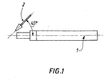
- the injection of gaseous CO 2 is carried out at the outlet of the oxygen cutting nozzle 1, the oxygen / CO 2 mixture thus taking place directly at the outlet of the nozzle 1.
- the axis of the nozzle 1 of the flame cutting torch and the axis of the CO 2 distribution nozzle 2 form an angle of 45 °.
- the method according to the invention can be applied, in particular to the steel industry and the cutting of very thick steel parts.
Landscapes
- Engineering & Computer Science (AREA)
- Mechanical Engineering (AREA)
- Arc Welding In General (AREA)
- Gas Burners (AREA)
- Laser Beam Processing (AREA)
Abstract
Description
- On envoie le CO2 en aval du gaz de coupe contenant de l'oxygène, en considérant le sens de formation de la saignée de coupe.
- On envoie le CO2 en direction de la saignée de coupe de sorte que le front de saignée soit soumis au flux de gaz de coupe contenant de l'oxygène et que le jet de CO2 contribue à chasser hors de la saignée les oxydes de fer se formant.
- Le gaz de coupe est de l'oxygène, de préférence de l'oxygène contenant moins de 1% d'impuretés, de préférence encore de l'oxygène contenant moins de 0,35% d'impuretés, de préférence moins de 0,1%.
- La pièce métallique à couper est une pièce d'acier ayant une épaisseur d'au moins 100 mm, de préférence d'au moins 180 mm.
- La pression du jet de CO2 est comprise entre 3,5 bar et 8 bar et/ou le débit de CO2 est compris entre 9 et 22,5 m3/h. Le débit de CO2 représente alors entre 2 et 5% environ du débit d'oxygène de coupe lorsque celui-ci est évalué à environ 450 m3/h.
- une source d'un gaz de coupe contenant de l'oxygène,
- une source de dioxyde de carbone,
- un chalumeau ou une lance thermique alimenté en gaz de coupe issu de ladite source de gaz de coupe, et
- au moins une buse de distribution de CO2 alimentée en CO2 par ladite source de dioxyde de carbone.
- débit d'oxygène de coupe : 450 m3/h,
- pression d'oxygène de coupe : 13.105 Pa,
- pression du gaz naturel de chauffe : 2,5.105 Pa,
- débit de CO2 : 15 m3/h,
- pression de CO2 : 4.105 Pa.
Claims (9)
- Procédé d'oxycoupage d'une pièce métallique contenant du fer, en particulier une pièce d'acier, dans lequel au moins une saignée de coupe est réalisée en soumettant ladite pièce à au moins un gaz de coupe contenant de l'oxygène, caractérisé en ce que, pendant le coupage de ladite pièce avec ledit gaz de coupe, on envoie du dioxyde de carbone (CO2) gazeux en direction de la saignée de coupe et en ce qu'on envoie le CO2 en aval du gaz de coupe contenant de l'oxygène, en considérant le sens de formation de la saignée de coupe.
- Procédé selon la revendication 1, caractérisé en ce qu'on envoie le CO2 en direction de la saignée de coupe de sorte que le front de saignée soit soumis au flux de gaz de coupe contenant de l'oxygène et que le jet de CO2 contribue à chasser hors de la saignée les oxydes de fer se formant.
- Procédé selon l'une des revendications 1 ou 2, caractérisé en ce que le gaz de coupe est de l'oxygène, de préférence de l'oxygène contenant moins de 1% d'impuretés, de préférence encore de l'oxygène contenant moins de 0,35% d'impuretés.
- Procédé selon l'une des revendications 1 à 3, caractérisé en ce que la pièce métallique à couper est une pièce d'acier ayant une épaisseur d'au moins 100 mm, de préférence d'au moins 180 mm.
- Procédé selon l'une des revendications 1 à 4, caractérisé en ce que la pression du jet de CO2 est comprise entre 3,5 bar et 8 bar.
- Procédé selon l'une des revendications 1 à 5, caractérisé en ce que le débit de CO2 représente environ 2 à 5% du débit d'oxygène de coupe.
- Installation d'oxycoupage susceptible de mettre en oeuvre un procédé selon l'une des revendications 1 à 6, comportant :une source d'un gaz de coupe contenant de l'oxygène,une source de dioxyde de carbone,un chalumeau ou une lance thermique alimenté en gaz de coupe issu de ladite source de gaz de coupe, etau moins une buse de distribution de CO2 alimentée en CO2 par ladite source de dioxyde de carbone, l'axe du chalumeau ou de la lance thermique et l'axe de la buse de distribution de CO2 formant entre eux un angle compris entre 0° et 70°.
- Installation selon la revendication 7, caractérisée en ce que l'axe du chalumeau ou de la lance thermique et l'axe de la buse de distribution de CO2 forment entre eux un angle de l'ordre de 30° à 50°.
- Utilisation d'une installation selon les revendications 7 ou 8 dans une opération d'oxycoupage de brames d'acier ayant une épaisseur d'au moins 180 mm.
Applications Claiming Priority (2)
| Application Number | Priority Date | Filing Date | Title |
|---|---|---|---|
| FR9905768A FR2793177B1 (fr) | 1999-05-06 | 1999-05-06 | Procede et installation pour reduire l'emission de fumees rousses en oxycoupage |
| FR9905768 | 1999-05-06 |
Publications (2)
| Publication Number | Publication Date |
|---|---|
| EP1052050A1 true EP1052050A1 (fr) | 2000-11-15 |
| EP1052050B1 EP1052050B1 (fr) | 2004-05-19 |
Family
ID=9545284
Family Applications (1)
| Application Number | Title | Priority Date | Filing Date |
|---|---|---|---|
| EP00401091A Expired - Lifetime EP1052050B1 (fr) | 1999-05-06 | 2000-04-19 | Procédé pour réduire l'émission de fumées rousses en oxycoupage |
Country Status (3)
| Country | Link |
|---|---|
| EP (1) | EP1052050B1 (fr) |
| DE (1) | DE60010794T2 (fr) |
| FR (1) | FR2793177B1 (fr) |
Cited By (1)
| Publication number | Priority date | Publication date | Assignee | Title |
|---|---|---|---|---|
| FR2928286A1 (fr) * | 2008-03-10 | 2009-09-11 | Air Liquide | Procede d'oxycoupage de paquets de toles empilees |
Citations (3)
| Publication number | Priority date | Publication date | Assignee | Title |
|---|---|---|---|---|
| US3216867A (en) * | 1963-04-29 | 1965-11-09 | Union Carbide Corp | Thermochemical scarfing process |
| WO1992004151A1 (fr) * | 1990-08-31 | 1992-03-19 | Productivity Xperts, Inc. | Procede et dispositif d'usinage a controle des copeaux ameliore |
| EP0866140A1 (fr) * | 1997-03-18 | 1998-09-23 | Praxair Technology, Inc. | Jet gazeux cohérent |
Family Cites Families (4)
| Publication number | Priority date | Publication date | Assignee | Title |
|---|---|---|---|---|
| US4289859A (en) * | 1980-06-02 | 1981-09-15 | Dow Corning Corporation | Non-bleeding transparent silicone additives for plastics |
| DE3047158A1 (de) * | 1980-12-15 | 1982-07-22 | Egon 5650 Solingen Evertz | Verfahren und vorrichtung zur abtragenden flaechenbehandlung von gegenstaenden aus hochkohlenstoffhaltigem eisen |
| DE3721685A1 (de) * | 1987-07-01 | 1989-01-12 | Aute Autogene Tech | Bandguss-brennschneidmaschine in stranggiessanlagen |
| US5021624A (en) * | 1988-04-11 | 1991-06-04 | Gene Rogers | Cutting tools for conventional and MIG electric welders |
-
1999
- 1999-05-06 FR FR9905768A patent/FR2793177B1/fr not_active Expired - Fee Related
-
2000
- 2000-04-19 EP EP00401091A patent/EP1052050B1/fr not_active Expired - Lifetime
- 2000-04-19 DE DE2000610794 patent/DE60010794T2/de not_active Expired - Fee Related
Patent Citations (3)
| Publication number | Priority date | Publication date | Assignee | Title |
|---|---|---|---|---|
| US3216867A (en) * | 1963-04-29 | 1965-11-09 | Union Carbide Corp | Thermochemical scarfing process |
| WO1992004151A1 (fr) * | 1990-08-31 | 1992-03-19 | Productivity Xperts, Inc. | Procede et dispositif d'usinage a controle des copeaux ameliore |
| EP0866140A1 (fr) * | 1997-03-18 | 1998-09-23 | Praxair Technology, Inc. | Jet gazeux cohérent |
Cited By (1)
| Publication number | Priority date | Publication date | Assignee | Title |
|---|---|---|---|---|
| FR2928286A1 (fr) * | 2008-03-10 | 2009-09-11 | Air Liquide | Procede d'oxycoupage de paquets de toles empilees |
Also Published As
| Publication number | Publication date |
|---|---|
| EP1052050B1 (fr) | 2004-05-19 |
| FR2793177B1 (fr) | 2001-08-03 |
| DE60010794D1 (de) | 2004-06-24 |
| FR2793177A1 (fr) | 2000-11-10 |
| DE60010794T2 (de) | 2005-06-02 |
Similar Documents
| Publication | Publication Date | Title |
|---|---|---|
| EP1335810B1 (fr) | Procede de coupage laser a haute vitesse avec gaz adapte | |
| FR2852541A1 (fr) | Procede de coupage plasma avec double flux de gaz | |
| EP2537623A1 (fr) | Procédé de soudage laser de type CO2 avec buse à jet dynamique | |
| FR2777214A1 (fr) | Torche et procede de coupage ou soudage a l'arc electrique | |
| FR2898529A1 (fr) | Soudo-brasage de pieces en acier avec fil en cuivre et melange gazeux oxydant | |
| CA2474527C (fr) | Melange gazeux ternaire utilisable en soudo-brasage de pieces galvanisees | |
| EP2282866B1 (fr) | Procede d'oxycoupage d'une piece en acier avec augmentation de la pression et/ou du debit de l'oxygene gazeux apres amorcage du percage | |
| CH703236B1 (fr) | Procédé de récupération de silicium dans des déchets de sciage. | |
| FR2634758A1 (fr) | Procede et dispositif de reparation d'un corps refractaire | |
| EP1052050B1 (fr) | Procédé pour réduire l'émission de fumées rousses en oxycoupage | |
| EP0847831B1 (fr) | Procédé de fabrication de fils fourrés étanches pour le soudage à l'arc | |
| FR2776550A1 (fr) | Procede de soudage ou de coupage plasma ou tig avec gaz non-oxydant a faible teneur en impuretes h2o et/ou o2 | |
| EP2078580B1 (fr) | Procédé de soudage MAG avec arc rotatif de faible énergie | |
| EP1149659A1 (fr) | Coupage laser de tôle galvanisée avec un mélange azote/oxygène en tant que gaz d'assistance | |
| EP1578177A1 (fr) | Procédé de coupage plasma avec double flux de gaz | |
| US1142355A (en) | Process of cutting metals. | |
| EP1194513B1 (fr) | Melange gazeux combustible et son utilisation en oxycoupage | |
| EP1044752A1 (fr) | Procédé de soudage MIG de l'aluminium et de ses alliages à régime pulsé ou spray non-modulé | |
| EP0922521B1 (fr) | Procédé d'oxycoupage mettant en oeuvre de l'oxygène de haute pureté sous haute pression | |
| FR2735563A1 (fr) | Procede de fusion d'une charge dans un four | |
| FR2917655A1 (fr) | Controle du cycle de percage en coupage plasma. | |
| JP2002283056A (ja) | 非消耗電極式ガスシールドアーク溶接方法 | |
| BE533249A (fr) | ||
| FR2928286A1 (fr) | Procede d'oxycoupage de paquets de toles empilees | |
| FR2852479A1 (fr) | Electrode a insert en hf-zr pour torche de coupage plasma |
Legal Events
| Date | Code | Title | Description |
|---|---|---|---|
| PUAI | Public reference made under article 153(3) epc to a published international application that has entered the european phase |
Free format text: ORIGINAL CODE: 0009012 |
|
| AK | Designated contracting states |
Kind code of ref document: A1 Designated state(s): DE FR GB IT |
|
| AX | Request for extension of the european patent |
Free format text: AL;LT;LV;MK;RO;SI |
|
| 17P | Request for examination filed |
Effective date: 20010515 |
|
| AKX | Designation fees paid |
Free format text: DE FR GB IT |
|
| RAP1 | Party data changed (applicant data changed or rights of an application transferred) |
Owner name: L'AIR LIQUIDE, S.A. A DIRECTOIRE ET CONSEIL DE SUR |
|
| 17Q | First examination report despatched |
Effective date: 20030402 |
|
| RTI1 | Title (correction) |
Free format text: METHOD USED TO DIMINISH RUSSET-RED FUMES IN AN OXYCUTTING OPERATION |
|
| GRAP | Despatch of communication of intention to grant a patent |
Free format text: ORIGINAL CODE: EPIDOSNIGR1 |
|
| GRAS | Grant fee paid |
Free format text: ORIGINAL CODE: EPIDOSNIGR3 |
|
| GRAA | (expected) grant |
Free format text: ORIGINAL CODE: 0009210 |
|
| AK | Designated contracting states |
Kind code of ref document: B1 Designated state(s): DE FR GB IT |
|
| PG25 | Lapsed in a contracting state [announced via postgrant information from national office to epo] |
Ref country code: GB Free format text: LAPSE BECAUSE OF FAILURE TO SUBMIT A TRANSLATION OF THE DESCRIPTION OR TO PAY THE FEE WITHIN THE PRESCRIBED TIME-LIMIT Effective date: 20040519 |
|
| REG | Reference to a national code |
Ref country code: GB Ref legal event code: FG4D Free format text: NOT ENGLISH |
|
| REF | Corresponds to: |
Ref document number: 60010794 Country of ref document: DE Date of ref document: 20040624 Kind code of ref document: P |
|
| GBV | Gb: ep patent (uk) treated as always having been void in accordance with gb section 77(7)/1977 [no translation filed] |
Effective date: 20040519 |
|
| PLBE | No opposition filed within time limit |
Free format text: ORIGINAL CODE: 0009261 |
|
| STAA | Information on the status of an ep patent application or granted ep patent |
Free format text: STATUS: NO OPPOSITION FILED WITHIN TIME LIMIT |
|
| 26N | No opposition filed |
Effective date: 20050222 |
|
| PGFP | Annual fee paid to national office [announced via postgrant information from national office to epo] |
Ref country code: FR Payment date: 20060313 Year of fee payment: 7 |
|
| PGFP | Annual fee paid to national office [announced via postgrant information from national office to epo] |
Ref country code: DE Payment date: 20060317 Year of fee payment: 7 |
|
| PGFP | Annual fee paid to national office [announced via postgrant information from national office to epo] |
Ref country code: IT Payment date: 20060430 Year of fee payment: 7 |
|
| PG25 | Lapsed in a contracting state [announced via postgrant information from national office to epo] |
Ref country code: DE Free format text: LAPSE BECAUSE OF NON-PAYMENT OF DUE FEES Effective date: 20071101 |
|
| PG25 | Lapsed in a contracting state [announced via postgrant information from national office to epo] |
Ref country code: FR Free format text: LAPSE BECAUSE OF NON-PAYMENT OF DUE FEES Effective date: 20070430 |
|
| PG25 | Lapsed in a contracting state [announced via postgrant information from national office to epo] |
Ref country code: IT Free format text: LAPSE BECAUSE OF NON-PAYMENT OF DUE FEES Effective date: 20070419 |