EP1052007A1 - Screw drum type filtration device - Google Patents
Screw drum type filtration device Download PDFInfo
- Publication number
- EP1052007A1 EP1052007A1 EP99972941A EP99972941A EP1052007A1 EP 1052007 A1 EP1052007 A1 EP 1052007A1 EP 99972941 A EP99972941 A EP 99972941A EP 99972941 A EP99972941 A EP 99972941A EP 1052007 A1 EP1052007 A1 EP 1052007A1
- Authority
- EP
- European Patent Office
- Prior art keywords
- plates
- openings
- fixed
- floating
- cylindrical space
- Prior art date
- Legal status (The legal status is an assumption and is not a legal conclusion. Google has not performed a legal analysis and makes no representation as to the accuracy of the status listed.)
- Withdrawn
Links
- 238000001914 filtration Methods 0.000 title claims abstract description 24
- 230000002093 peripheral effect Effects 0.000 claims abstract description 17
- 239000010802 sludge Substances 0.000 claims description 16
- XLYOFNOQVPJJNP-UHFFFAOYSA-N water Substances O XLYOFNOQVPJJNP-UHFFFAOYSA-N 0.000 description 10
- 230000000694 effects Effects 0.000 description 5
- 239000000706 filtrate Substances 0.000 description 5
- 239000002245 particle Substances 0.000 description 5
- 238000010276 construction Methods 0.000 description 4
- 230000033001 locomotion Effects 0.000 description 4
- 125000006850 spacer group Chemical group 0.000 description 3
- 230000005540 biological transmission Effects 0.000 description 1
- 230000006835 compression Effects 0.000 description 1
- 238000007906 compression Methods 0.000 description 1
- 230000007797 corrosion Effects 0.000 description 1
- 238000005260 corrosion Methods 0.000 description 1
- 238000009434 installation Methods 0.000 description 1
- 238000004519 manufacturing process Methods 0.000 description 1
- 230000003313 weakening effect Effects 0.000 description 1
Images


Classifications
-
- B—PERFORMING OPERATIONS; TRANSPORTING
- B01—PHYSICAL OR CHEMICAL PROCESSES OR APPARATUS IN GENERAL
- B01D—SEPARATION
- B01D29/00—Filters with filtering elements stationary during filtration, e.g. pressure or suction filters, not covered by groups B01D24/00 - B01D27/00; Filtering elements therefor
- B01D29/11—Filters with filtering elements stationary during filtration, e.g. pressure or suction filters, not covered by groups B01D24/00 - B01D27/00; Filtering elements therefor with bag, cage, hose, tube, sleeve or like filtering elements
- B01D29/13—Supported filter elements
- B01D29/23—Supported filter elements arranged for outward flow filtration
-
- B—PERFORMING OPERATIONS; TRANSPORTING
- B01—PHYSICAL OR CHEMICAL PROCESSES OR APPARATUS IN GENERAL
- B01D—SEPARATION
- B01D29/00—Filters with filtering elements stationary during filtration, e.g. pressure or suction filters, not covered by groups B01D24/00 - B01D27/00; Filtering elements therefor
- B01D29/44—Edge filtering elements, i.e. using contiguous impervious surfaces
- B01D29/46—Edge filtering elements, i.e. using contiguous impervious surfaces of flat, stacked bodies
-
- B—PERFORMING OPERATIONS; TRANSPORTING
- B01—PHYSICAL OR CHEMICAL PROCESSES OR APPARATUS IN GENERAL
- B01D—SEPARATION
- B01D29/00—Filters with filtering elements stationary during filtration, e.g. pressure or suction filters, not covered by groups B01D24/00 - B01D27/00; Filtering elements therefor
- B01D29/62—Regenerating the filter material in the filter
- B01D29/64—Regenerating the filter material in the filter by scrapers, brushes, nozzles, or the like, acting on the cake side of the filtering element
- B01D29/6469—Regenerating the filter material in the filter by scrapers, brushes, nozzles, or the like, acting on the cake side of the filtering element scrapers
- B01D29/6476—Regenerating the filter material in the filter by scrapers, brushes, nozzles, or the like, acting on the cake side of the filtering element scrapers with a rotary movement with respect to the filtering element
-
- B—PERFORMING OPERATIONS; TRANSPORTING
- B01—PHYSICAL OR CHEMICAL PROCESSES OR APPARATUS IN GENERAL
- B01D—SEPARATION
- B01D33/00—Filters with filtering elements which move during the filtering operation
- B01D33/06—Filters with filtering elements which move during the filtering operation with rotary cylindrical filtering surfaces, e.g. hollow drums
- B01D33/11—Filters with filtering elements which move during the filtering operation with rotary cylindrical filtering surfaces, e.g. hollow drums arranged for outward flow filtration
-
- B—PERFORMING OPERATIONS; TRANSPORTING
- B01—PHYSICAL OR CHEMICAL PROCESSES OR APPARATUS IN GENERAL
- B01D—SEPARATION
- B01D33/00—Filters with filtering elements which move during the filtering operation
- B01D33/27—Filters with filtering elements which move during the filtering operation with rotary filtering surfaces, which are neither cylindrical nor planar, e.g. helical surfaces
- B01D33/275—Filters with filtering elements which move during the filtering operation with rotary filtering surfaces, which are neither cylindrical nor planar, e.g. helical surfaces using contiguous impervious surfaces
-
- B—PERFORMING OPERATIONS; TRANSPORTING
- B01—PHYSICAL OR CHEMICAL PROCESSES OR APPARATUS IN GENERAL
- B01D—SEPARATION
- B01D33/00—Filters with filtering elements which move during the filtering operation
- B01D33/44—Regenerating the filter material in the filter
- B01D33/46—Regenerating the filter material in the filter by scrapers, brushes nozzles or the like acting on the cake-side of the filtering element
- B01D33/466—Regenerating the filter material in the filter by scrapers, brushes nozzles or the like acting on the cake-side of the filtering element scrapers
Definitions
- the present invention relates to a screw drum type filter for filtering sludge containing suspended particles to separate it into filtrate and dehydrated cake.
- a filter of this system comprises a filter cylinder installed in a substantial range in a drum excluding the opposite ends of the drum for filtering sludge radially from inside to outside of the cylinder, a number of through-holes formed in the peripheral surface of the drum in said substantial range, a screw installed throughout the length of the drum to extend through said filter cylinder, the spaces in said drum at opposite ends thereof being used as an inlet chamber for sludge and an outlet chamber for dehydrated cake.
- the filtration passage in the filter cylinder is defined by small clearances between alternating annular fixed and movable plates that constitute said cylinder.
- a shaft equipped with a cam key is fitted in circular holes formed in the lower ends of the movable plates and is eccentrically driven while supporting the weight of the plates while a fulcrum bar is loosely fitted in separate circular holes formed in the upper ends of the movable plates to effect vertical and transverse positional control.
- the cam-key-equipped shaft disposed at a position corresponding to the lower ends of the movable plates, the water forced out from between the plates of the filter cylinder (which water still contains some suspended particles) flows down onto the shaft and then into the bearings at the opposite ends to wear them.
- the opening edge shapes of the fixed and movable plates are generally triangular-wavelike serrations, rather than typical round shapes, formed along the circular base lines so as to increase the area of contact with sludge; with such arrangement, however, the suspended particles in the sludge to be processed accumulate in the triangular wavelike troughs of the opening edges, weakening the filtration effect between plates and, in some cases, damaging the vane edges of the screw.
- a first object of the present invention is to provide a screw drum type filter wherein a cam or shaft means for direct contact drive of the movable plates of a filter cylinder so as to swing the movable plates is placed at a position sufficiently remote from the middle lower portion of the filter cylinder to prevent the filtrate water forced out from the clearances between the plates from falling down onto said means in large amounts.
- a second object of the invention is to provide a screw drum type filter wherein the opening edges of the fixed and movable plates are shaped such that suspended particles hardly accumulate while the area of contact with sludge to be processed is maintained increased to some degree.
- a screw drum filter according to the invention comprises
- each floating plate is contacted and supported by the eccentric shafts at the equi-level positions in its peripheral edge sufficiently separated from the middle lower portion thereof; therefore, the water forced out through the filtration clearances between the plates mostly moves along the outer peripheral edges of the movable and fixed plates to reach the lower portions of the plates below the cylindrical shaft, whereupon it flows down, with the result that it hardly collects on the eccentric shafts disposed right and left and the bearings are sufficiently protected against entry of the filtrate water.
- the term floating plate is used in almost the same meaning as that of the term movable plate in the conventional filter, and the floating plate is named in consideration of the function of producing a rotation whose speed transmission ratio varies.
- the screw drum filter according to the invention is such that the opening contours of the fixed and floating plates are defined by rounded wavelike closed curves along the circular base lines.
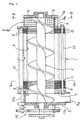
- the numeral 1 denotes a filtration cylinder for a screw drum filter; and 2 denotes a screw fitted to and extending through the cylindrical inner peripheral contour 3 of the filtration cylinder 1, the opposite ends thereof reaching an inlet case 4 and an outlet case 5.
- the filtration cylinder 1 is composed, between a front end plate 6 and a rear end plate 7, of an approximately horizontally extending alternately superposed array of a number of fixed plates 8 having openings, typically circular, and a number of annular floating plates 9 having geometrically similar openings slightly larger in diameter than the openings in said fixed plates 8 and also having circular outer peripheries, wherein the small clearances between such plates provide filtration clearances for sludge to be processed.
- the cylindrical inner peripheral contour 3 of the filtration cylinder 1 is defined by the row of openings in the fixed plates 8 arranged.
- a plurality of support bars 10 (in Fig. 1, there appears only one positioned at the lower end) installed between the front and rear end plates 6 and 7 are inserted into the support holes in alternately disposed fixed plates 8 and spacers 11 and are fixed together in close contact with each other, while the floating plates 9 are positioned in spaces defined by the thickness of the spacers 11.
- These floating plates 9 are supported, position-controlled, rotated (around their own axes) and swung by a plurality of eccentric shafts 12 (in Fig. 1, there appears only one positioned at the upper end) contacting their outer peripheral edges exposed beyond the outer edges of the fixed plates 8.
- each fixed plate 8 is an inverted triangular plate having its three apexes cut off, with the support bars 10 and spacers 11 disposed at such apexes.
- the opening edge of the fixed plate 8 defines said cylindrical inner peripheral contour 3 and in Fig. 2 the floating plate 9 disposed on either side of said plate 8 swings in a plane surrounded by three spaces 11 and within a range in which the opening edge 13 thereof does not enter the cylindrical inner peripheral contour 3.
- Three eccentric shafts 12 are rotatably installed between intermediate extensions 7a, 7b, 7c on the individual sides of the rear end plate 7, which has a basic shape congruent to the shape of the fixed plate 8, and intermediate extensions 6a, 6b, 6c (Fig. 4) of the front end plate 6 corresponding thereto, and are driven in operative connection to the screw 2 by a gear train 14 (Fig. 1) disposed outside the outlet case 5.
- the eccentric shafts 12 may be driven separately from or independently of the screw 2 by some other driving mechanism.
- the circular outer peripheral edge of the floating plate 9 projects beyond the middle portions of the three longer sides of the fixed plate 8 within said range of swing movement and is contacted and supported by the three eccentric shafts 12, all of the floating plates 9 being rotatively swung by the eccentric rotation of these eccentric shafts 12.
- Each eccentric shaft 12 is of integrated construction having small-diametered eccentric shafts 12a projecting from the opposite ends of the main body shaft; therefore, when the outer periphery of the main body shaft effects rotary movement, the floating plate 9 is frictionally driven thereby and also produces rotary motion.
- the floating plate 9 may be such that it is supported by the eccentric shafts only at its portions exposed beyond the adjacent longer sides of the fixed plate 8. This means that the floating plate 9 suffices for the purpose so long as it is constructed such that at least two equi-level regions in the lower portions of the floating plate 9 are exposed beyond the outer edge of the fixed plate 8.
- Fig. 3 shows the screw 2 rotated clockwise through 25° from the state shown in Fig. 2 and the eccentric shafts 12 rotated concurrently therewith counterclockwise through about 45°.
- the opening edge 13 of the floating plate 9 and the uppermost portion of the opening edge of the fixed plate 8 are separated farthest from each other and the lowermost portions of opening edges of the two plates approximately coincide with each other
- the opening edge 13 of the floating plate and the portion of the opening edge of the fixed plate opposed to the eccentric shaft 12 positioned at 30° lower right are separated farthest and their portions opposed to the eccentric shaft 12 positioned at 30° upper right approximately coincide with each other.
- the floating plate 9 swings in this manner in operative connection with the rotation of the screw 2.
- Fig. 4 is a section taken along the line B-B in Fig. 1, showing the construction of the inside of the inlet case 4.
- An U-type curved plate 16 having a number of small holes 15 and also having a curved surface slidably contacting the outer edges of the vanes of the screw 2 is installed in the case 4 to extend between the front and rear walls of the case (see Fig. 1), so as to receive sludge to be processed from the open upper end.
- the lower end of the inlet case 4 may be formed in a bag type having no opening 4a, in which case the introduced sludge to be processed will be fed as it is to the filtration cylinder 1.
- the sludge to be processed that is gradually compressed in the filtration cylinder 1 by the screw 2 is radially filtered through the filtration clearances permanently (slidingly) regenerated between the floating plates 9 and the fixed plates 8 by the aforesaid swing of the floating plates 9, and the filtrate water component moves along the peripheral edges of these plates 8 and 9, the greater part of which water component reaches the lower ends of the fixed plates 8 positioned between two lower eccentric shafts 12 and then flows down therefrom, without flowing into the bearings for the eccentric shafts 12, so that it does not cause corrosion or wear of the bearings.
- the thus compressed and concentrated cake from the sludge is discharged through the outlet port 5a at the lower end of the outlet case 5.
- Figs. 5 and 6 are views showing preferred opening shapes for the fixed and floating plates 8 and 9, respectively, and the contours of their opening edges 3a and 13a are defined by rounded wavelike closed curves along the circular base lines.
- the opening edge 13a of the floating plate is somewhat larger than the opening edge 3a of the fixed plate so that the former does not enter the latter during operation.
- the opening edges 3a and 13a maintain the area of contact with the sludge to be processed somewhat larger than in the case of a simple circle, thereby increasing the filtration efficiency.
- the opening edges are not pointed as in the case of triangular waves, there is obtained an effect that suspended particles hardly accumulate.
- the present invention provides a screw drum device including a means (eccentric shafts 12) for direct contact with the floating plates and having a simple construction adapted to prevent the filtrate water from entering the bearings for said means.
- the openings in the fixed and floating plate may be in the shape of rounded waves so as to provide a long-life screw drum device having a high degree of filtration efficiency.
Landscapes
- Chemical & Material Sciences (AREA)
- Chemical Kinetics & Catalysis (AREA)
- Filtration Of Liquid (AREA)
- Treatment Of Sludge (AREA)
Abstract
Description
- The present invention relates to a screw drum type filter for filtering sludge containing suspended particles to separate it into filtrate and dehydrated cake.
- As for conventional screw drum type filters, there is, for example, a through-screw type filter cylinder installation system, as disclosed in Japanese Patent No. 1520106. A filter of this system comprises a filter cylinder installed in a substantial range in a drum excluding the opposite ends of the drum for filtering sludge radially from inside to outside of the cylinder, a number of through-holes formed in the peripheral surface of the drum in said substantial range, a screw installed throughout the length of the drum to extend through said filter cylinder, the spaces in said drum at opposite ends thereof being used as an inlet chamber for sludge and an outlet chamber for dehydrated cake. The filtration passage in the filter cylinder is defined by small clearances between alternating annular fixed and movable plates that constitute said cylinder.
- In the above arrangement, in order to swing the movable plates, a shaft equipped with a cam key is fitted in circular holes formed in the lower ends of the movable plates and is eccentrically driven while supporting the weight of the plates while a fulcrum bar is loosely fitted in separate circular holes formed in the upper ends of the movable plates to effect vertical and transverse positional control. However, in such arrangement with the cam-key-equipped shaft disposed at a position corresponding to the lower ends of the movable plates, the water forced out from between the plates of the filter cylinder (which water still contains some suspended particles) flows down onto the shaft and then into the bearings at the opposite ends to wear them.
- The opening edge shapes of the fixed and movable plates are generally triangular-wavelike serrations, rather than typical round shapes, formed along the circular base lines so as to increase the area of contact with sludge; with such arrangement, however, the suspended particles in the sludge to be processed accumulate in the triangular wavelike troughs of the opening edges, weakening the filtration effect between plates and, in some cases, damaging the vane edges of the screw.
- A first object of the present invention is to provide a screw drum type filter wherein a cam or shaft means for direct contact drive of the movable plates of a filter cylinder so as to swing the movable plates is placed at a position sufficiently remote from the middle lower portion of the filter cylinder to prevent the filtrate water forced out from the clearances between the plates from falling down onto said means in large amounts.
- A second object of the invention is to provide a screw drum type filter wherein the opening edges of the fixed and movable plates are shaped such that suspended particles hardly accumulate while the area of contact with sludge to be processed is maintained increased to some degree.
- To achieve the first object, a screw drum filter according to the invention comprises
- a) a filter cylinder composed of an approximately horizontally extending alternately superposed array of a number of annular fixed plates having circular or approximately circular openings, and a number of annular floating plates having geometrically similar openings slightly larger in diameter than the openings in said fixed plates and also having circular outer peripheries, with small filtration clearances defined, the row of openings in said fixed plates defining a cylindrical space having a fixed inner peripheral contour, it being arranged that when the row of openings in said floating plates is positioned outside said cylindrical space, at least two equi-level regions in the lower portion of the outer periphery of the floating plate are exposed beyond the outer edge of the fixed plate,
- b) a screw (2) extending through said cylindrical space for compression-feeding sludge to be processed in a direction with one end of the cylindrical space in said filtration cylinder as the inlet end and the other end as the outlet end,
- c) at least two eccentric shafts contact-wise supporting said exposed outer peripheral portions of said floating plates and eccentrically rotated, so as to swing the floating plates, and
- d) a driving mechanism for operatively connecting said screw pitch and said eccentric shafts or for individually driving them.
-
- According to the above arrangement, each floating plate is contacted and supported by the eccentric shafts at the equi-level positions in its peripheral edge sufficiently separated from the middle lower portion thereof; therefore, the water forced out through the filtration clearances between the plates mostly moves along the outer peripheral edges of the movable and fixed plates to reach the lower portions of the plates below the cylindrical shaft, whereupon it flows down, with the result that it hardly collects on the eccentric shafts disposed right and left and the bearings are sufficiently protected against entry of the filtrate water. In addition, the term floating plate is used in almost the same meaning as that of the term movable plate in the conventional filter, and the floating plate is named in consideration of the function of producing a rotation whose speed transmission ratio varies.
- Further, to achieve the second object, the screw drum filter according to the invention is such that the opening contours of the fixed and floating plates are defined by rounded wavelike closed curves along the circular base lines.
-
- Fig. 1 is a longitudinal section of a basic embodiment;
- Fig. 2 is a section taken along the line A-A in Fig. 1;
- Fig. 3 is a section similar to Fig. 2, showing a screw and movable plates rotated from the state of Fig. 2;
- Fig. 4 is a section taken along the line B-B in Fig. 1, showing an inlet in the basic embodiment;
- Fig. 5 is a plan view showing an example of preferred shape for the fixed plates; and
- Fig. 6 is a plan view showing an example of preferred shape for the movable plates
-
- Screw drum filters according to preferred embodiments of the invention will now be described with reference to the drawings.
- In Fig. 1, the
numeral 1 denotes a filtration cylinder for a screw drum filter; and 2 denotes a screw fitted to and extending through the cylindrical innerperipheral contour 3 of thefiltration cylinder 1, the opposite ends thereof reaching aninlet case 4 and anoutlet case 5. Thefiltration cylinder 1 is composed, between afront end plate 6 and a rear end plate 7, of an approximately horizontally extending alternately superposed array of a number offixed plates 8 having openings, typically circular, and a number of annularfloating plates 9 having geometrically similar openings slightly larger in diameter than the openings in saidfixed plates 8 and also having circular outer peripheries, wherein the small clearances between such plates provide filtration clearances for sludge to be processed. The cylindrical innerperipheral contour 3 of thefiltration cylinder 1 is defined by the row of openings in thefixed plates 8 arranged. In such disposition of thefixed plate 8, a plurality of support bars 10 (in Fig. 1, there appears only one positioned at the lower end) installed between the front andrear end plates 6 and 7 are inserted into the support holes in alternately disposedfixed plates 8 andspacers 11 and are fixed together in close contact with each other, while thefloating plates 9 are positioned in spaces defined by the thickness of thespacers 11. Thesefloating plates 9 are supported, position-controlled, rotated (around their own axes) and swung by a plurality of eccentric shafts 12 (in Fig. 1, there appears only one positioned at the upper end) contacting their outer peripheral edges exposed beyond the outer edges of thefixed plates 8. - Referring to Fig. 2, which is a section taken along the line A-A in Fig. 1, each
fixed plate 8 is an inverted triangular plate having its three apexes cut off, with thesupport bars 10 andspacers 11 disposed at such apexes. The opening edge of thefixed plate 8 defines said cylindrical innerperipheral contour 3 and in Fig. 2 thefloating plate 9 disposed on either side ofsaid plate 8 swings in a plane surrounded by threespaces 11 and within a range in which theopening edge 13 thereof does not enter the cylindrical innerperipheral contour 3. Threeeccentric shafts 12 are rotatably installed between intermediate extensions 7a, 7b, 7c on the individual sides of the rear end plate 7, which has a basic shape congruent to the shape of thefixed plate 8, andintermediate extensions 6a, 6b, 6c (Fig. 4) of thefront end plate 6 corresponding thereto, and are driven in operative connection to thescrew 2 by a gear train 14 (Fig. 1) disposed outside theoutlet case 5. In addition, theeccentric shafts 12 may be driven separately from or independently of thescrew 2 by some other driving mechanism. - The circular outer peripheral edge of the
floating plate 9 projects beyond the middle portions of the three longer sides of thefixed plate 8 within said range of swing movement and is contacted and supported by the threeeccentric shafts 12, all of thefloating plates 9 being rotatively swung by the eccentric rotation of theseeccentric shafts 12. Eacheccentric shaft 12 is of integrated construction having small-diameteredeccentric shafts 12a projecting from the opposite ends of the main body shaft; therefore, when the outer periphery of the main body shaft effects rotary movement, thefloating plate 9 is frictionally driven thereby and also produces rotary motion. However, the opposite surfaces of thefloating plate 9 rubs against thefixed plates 8 with small filtration clearances defined therebetween, and since this produces a frictional resistance, it is thought that in the relation between this frictional resistance and the frictional resistance for the outer periphery versus theeccentric shaft 12, a slight amount of rotation of thefloating plate 9 is produced. In order to reduce the frictional resistance for the outer periphery of thefloating plate 9 versus theeccentric shaft 12, it is possible to construct theeccentric shaft 12 as a so-called eccentric cam or the like so that the peripheral surface may perform eccentric vibration alone without producing rotary movement. However, if there is no problem in requiring additional energy to rotate the floating plate also, it is obvious that positive production and utilization of this rotation lead to preferred re-formation of the filtration clearances and to a further increase in the filterability. - In addition, the
floating plate 9 may be such that it is supported by the eccentric shafts only at its portions exposed beyond the adjacent longer sides of thefixed plate 8. This means that thefloating plate 9 suffices for the purpose so long as it is constructed such that at least two equi-level regions in the lower portions of thefloating plate 9 are exposed beyond the outer edge of thefixed plate 8. - Fig. 3 shows the
screw 2 rotated clockwise through 25° from the state shown in Fig. 2 and theeccentric shafts 12 rotated concurrently therewith counterclockwise through about 45°. In Fig. 2, theopening edge 13 of thefloating plate 9 and the uppermost portion of the opening edge of thefixed plate 8 are separated farthest from each other and the lowermost portions of opening edges of the two plates approximately coincide with each other, whereas in the state of Fig. 3 theopening edge 13 of the floating plate and the portion of the opening edge of the fixed plate opposed to theeccentric shaft 12 positioned at 30° lower right are separated farthest and their portions opposed to theeccentric shaft 12 positioned at 30° upper right approximately coincide with each other. It will be understood that thefloating plate 9 swings in this manner in operative connection with the rotation of thescrew 2. - Fig. 4 is a section taken along the line B-B in Fig. 1, showing the construction of the inside of the
inlet case 4. An U-typecurved plate 16 having a number ofsmall holes 15 and also having a curved surface slidably contacting the outer edges of the vanes of thescrew 2 is installed in thecase 4 to extend between the front and rear walls of the case (see Fig. 1), so as to receive sludge to be processed from the open upper end. - In the construction of the basic embodiment described above, when the
screw 2 is driven, theeccentric shafts 12 are rotated simultaneously therewith through thegear train 14, so that thefloating plates 9 swing, as described above. The sludge to be processed that is introduced into the U-typecurved plate 16 in thecase 4 is propelled and fed into thefiltration cylinder 1 by thescrew 2, said sludge being compressed by the compression effect of the screw to have part of its water component forced out through thesmall holes 15 in the U-typecurved plate 16, said water component being discharged through the lower end opening 4a in theinlet case 4. In addition, in the case where such U-type curved plate is not used, the lower end of theinlet case 4 may be formed in a bag type having noopening 4a, in which case the introduced sludge to be processed will be fed as it is to thefiltration cylinder 1. The sludge to be processed that is gradually compressed in thefiltration cylinder 1 by thescrew 2 is radially filtered through the filtration clearances permanently (slidingly) regenerated between thefloating plates 9 and thefixed plates 8 by the aforesaid swing of thefloating plates 9, and the filtrate water component moves along the peripheral edges of theseplates fixed plates 8 positioned between two lowereccentric shafts 12 and then flows down therefrom, without flowing into the bearings for theeccentric shafts 12, so that it does not cause corrosion or wear of the bearings. The thus compressed and concentrated cake from the sludge is discharged through theoutlet port 5a at the lower end of theoutlet case 5. - Figs. 5 and 6 are views showing preferred opening shapes for the fixed and
floating plates - As has been described so far, the present invention provides a screw drum device including a means (eccentric shafts 12) for direct contact with the floating plates and having a simple construction adapted to prevent the filtrate water from entering the bearings for said means. Further, the openings in the fixed and floating plate may be in the shape of rounded waves so as to provide a long-life screw drum device having a high degree of filtration efficiency.
Claims (3)
- A screw drum type filter comprising;a) a filter cylinder (1) composed of an approximately horizontally extending alternately superposed array of a number of annular fixed plates (8) having circular or approximately circular openings, and a number of annular floating plates (9) having geometrically similar openings (13) slightly larger in diameter than the openings in said fixed plates and also having circular outer peripheries, with small filtration clearances defined, the row of openings in said fixed plates defining a cylindrical space having a fixed inner peripheral contour (3), it being arranged that when the row of openings in said floating plates is positioned outside said cylindrical space, at least two equi-level regions in the lower portion of the floating plate are exposed beyond the outer edges of the fixed plate,b) a screw (2) extending through said cylindrical space for compression-feeding sludge to be processed in a direction with one end of the cylindrical space in said filtration cylinder as the inlet end and the other end as the outlet end,c) at least two eccentric shafts contact-wise supporting said exposed outer peripheral portions of said floating plates and eccentrically rotated, so as to drive the floating plates at least in a swing fashion, andd) a driving mechanism for operatively connecting said screw pitch and said eccentric shafts (12) or for individually driving them.
- A filer as set forth in Claim 1, characterized in that said floating plates are swung and rotation-driven by at least said two eccentric shafts.
- A filer as set forth in Claim 1 or 2, characterized in that the opening contours of said fixed and floating plates are defined by rounded wavelike closed curves along the circular base lines.
Applications Claiming Priority (3)
| Application Number | Priority Date | Filing Date | Title |
|---|---|---|---|
| JP34278998 | 1998-12-02 | ||
| JP34278998 | 1998-12-02 | ||
| PCT/JP1999/006436 WO2000032292A1 (en) | 1998-12-02 | 1999-11-18 | Screw drum type filtration device |
Publications (2)
| Publication Number | Publication Date |
|---|---|
| EP1052007A1 true EP1052007A1 (en) | 2000-11-15 |
| EP1052007A4 EP1052007A4 (en) | 2001-04-25 |
Family
ID=18356520
Family Applications (1)
| Application Number | Title | Priority Date | Filing Date |
|---|---|---|---|
| EP99972941A Withdrawn EP1052007A4 (en) | 1998-12-02 | 1999-11-18 | Screw drum type filtration device |
Country Status (9)
| Country | Link |
|---|---|
| US (1) | US6338411B1 (en) |
| EP (1) | EP1052007A4 (en) |
| KR (1) | KR20010034447A (en) |
| CN (1) | CN1154529C (en) |
| AU (1) | AU763047B2 (en) |
| CA (1) | CA2319075A1 (en) |
| NZ (1) | NZ506137A (en) |
| TW (1) | TW490312B (en) |
| WO (1) | WO2000032292A1 (en) |
Cited By (3)
| Publication number | Priority date | Publication date | Assignee | Title |
|---|---|---|---|---|
| EP2363278A1 (en) * | 2010-03-01 | 2011-09-07 | Alonso Sánchez Osma | Device for separating solids from water |
| EP3613489A4 (en) * | 2017-04-21 | 2020-11-04 | Wu, Yunping | Laminated spiral solid-liquid separator with torsional pendulum motion |
| EP3613574A4 (en) * | 2017-04-21 | 2020-12-02 | Wu, Yunping | Multi-shaft laminated spiral solid-liquid separator with pendulum motion |
Families Citing this family (25)
| Publication number | Priority date | Publication date | Assignee | Title |
|---|---|---|---|---|
| JP4480864B2 (en) * | 2000-08-07 | 2010-06-16 | 株式会社鶴見製作所 | Annular movable plate for screw type filter dehydrator |
| KR100413164B1 (en) * | 2001-06-27 | 2003-12-31 | (주)오에치케이 | Screw type solid liquid separating apparatus |
| KR100413165B1 (en) * | 2001-06-27 | 2003-12-31 | (주)오에치케이 | Screw type solid liquid separating apparatus |
| TW200632147A (en) * | 2004-11-12 | 2006-09-16 | ||
| KR100714417B1 (en) * | 2006-06-09 | 2007-05-04 | 주식회사 유천엔지니어링 | Multi disk outer barrel rotating type sludge dehydration epuipment of screw type |
| US7905994B2 (en) * | 2007-10-03 | 2011-03-15 | Moses Lake Industries, Inc. | Substrate holder and electroplating system |
| US20090188553A1 (en) * | 2008-01-25 | 2009-07-30 | Emat Technology, Llc | Methods of fabricating solar-cell structures and resulting solar-cell structures |
| CN101507887B (en) * | 2008-12-27 | 2011-11-23 | 上海索原环境科技有限公司 | Crawling type separator and realization method thereof |
| US8262894B2 (en) | 2009-04-30 | 2012-09-11 | Moses Lake Industries, Inc. | High speed copper plating bath |
| KR100978040B1 (en) * | 2010-02-22 | 2010-08-26 | (주)에이알케이 | Dewatering device for sludge |
| US20130200010A1 (en) * | 2010-04-21 | 2013-08-08 | The Warb Trust (No. 1 Trust 13337/99) | Sludge treatment system and method |
| KR101189731B1 (en) | 2010-07-30 | 2012-10-10 | (주)태화종합기술공사 | A Screw type dehydrator |
| JP4871437B1 (en) | 2011-01-24 | 2012-02-08 | アムコン株式会社 | Solid-liquid separator |
| KR101180639B1 (en) * | 2012-07-27 | 2012-09-18 | 최갑진 | Moving type screw dewatering equipment |
| JP5854958B2 (en) * | 2012-09-19 | 2016-02-09 | 株式会社鶴見製作所 | Solid-liquid separator |
| CN103835058A (en) * | 2012-11-20 | 2014-06-04 | 吴江市利群纺织有限公司 | Water inlet filter screen mechanism of water jet loom |
| WO2015004707A1 (en) | 2013-07-08 | 2015-01-15 | アムコン株式会社 | Device for concentrating object to be treated |
| CN105058842B (en) * | 2015-06-11 | 2018-01-23 | 安尼康(福建)环保设备有限公司 | It is a kind of that there is the equipment for separating liquid from solid for partly cutting ring |
| CN105500755A (en) * | 2016-01-27 | 2016-04-20 | 河南工程学院 | Abrasion-free abrasive disc type solid-liquid separator |
| CN105642001A (en) * | 2016-03-07 | 2016-06-08 | 东莞市威力固电路板设备有限公司 | Filter system with drum |
| CN108211450B (en) * | 2018-03-19 | 2020-04-24 | 亚太泵阀有限公司 | Sewage filtering treatment device |
| CN110721896A (en) * | 2019-10-24 | 2020-01-24 | 安徽省环境科学研究院 | Efficient water-saving starch slurry residue separation sieve and separation method |
| CN110893293B (en) * | 2019-12-08 | 2022-01-11 | 江苏佳森环保科技有限公司 | Wastewater treatment equipment with automatic cleaning function |
| CN113521839B (en) * | 2021-08-17 | 2023-01-31 | 浙江理工大学科技与艺术学院 | Circulating energy-saving equipment capable of recycling printing and dyeing sewage |
| CN216155724U (en) * | 2021-09-02 | 2022-04-01 | 吴云萍 | Non-abrasion lamination spiral dewatering equipment with detachable driving device |
Citations (1)
| Publication number | Priority date | Publication date | Assignee | Title |
|---|---|---|---|---|
| US3802566A (en) * | 1972-05-24 | 1974-04-09 | H Hata | Filter |
Family Cites Families (7)
| Publication number | Priority date | Publication date | Assignee | Title |
|---|---|---|---|---|
| US4177148A (en) * | 1978-03-03 | 1979-12-04 | Hach Chemical Company | Mechanical strainer |
| JPS59218298A (en) * | 1983-05-27 | 1984-12-08 | Sanshu Kaken Kogyo Kk | Screw press dehydrator having filter part consisting of multiple plates |
| JPS6019012A (en) | 1983-07-12 | 1985-01-31 | Sasaki Goro | Screw type filtering method and apparatus thereof |
| US4781615A (en) | 1987-08-31 | 1988-11-01 | Amp Incorporated | Cable terminating cover retention system |
| GB8825259D0 (en) * | 1988-10-25 | 1988-11-30 | Byers E V | Rotary screening device |
| JP2501173Y2 (en) * | 1991-02-27 | 1996-06-12 | 石垣機工株式会社 | Outer cylinder rotary screw press |
| JPH0763873B2 (en) * | 1991-12-20 | 1995-07-12 | 富国工業株式会社 | Rotary sieve |
-
1999
- 1999-11-18 AU AU11827/00A patent/AU763047B2/en not_active Ceased
- 1999-11-18 NZ NZ506137A patent/NZ506137A/en unknown
- 1999-11-18 US US09/601,252 patent/US6338411B1/en not_active Expired - Fee Related
- 1999-11-18 KR KR1020007008230A patent/KR20010034447A/en not_active Application Discontinuation
- 1999-11-18 CA CA002319075A patent/CA2319075A1/en not_active Abandoned
- 1999-11-18 WO PCT/JP1999/006436 patent/WO2000032292A1/en not_active Application Discontinuation
- 1999-11-18 EP EP99972941A patent/EP1052007A4/en not_active Withdrawn
- 1999-11-18 CN CNB998025828A patent/CN1154529C/en not_active Expired - Fee Related
-
2000
- 2000-06-09 TW TW089111296A patent/TW490312B/en not_active IP Right Cessation
Patent Citations (1)
| Publication number | Priority date | Publication date | Assignee | Title |
|---|---|---|---|---|
| US3802566A (en) * | 1972-05-24 | 1974-04-09 | H Hata | Filter |
Non-Patent Citations (1)
| Title |
|---|
| See also references of WO0032292A1 * |
Cited By (3)
| Publication number | Priority date | Publication date | Assignee | Title |
|---|---|---|---|---|
| EP2363278A1 (en) * | 2010-03-01 | 2011-09-07 | Alonso Sánchez Osma | Device for separating solids from water |
| EP3613489A4 (en) * | 2017-04-21 | 2020-11-04 | Wu, Yunping | Laminated spiral solid-liquid separator with torsional pendulum motion |
| EP3613574A4 (en) * | 2017-04-21 | 2020-12-02 | Wu, Yunping | Multi-shaft laminated spiral solid-liquid separator with pendulum motion |
Also Published As
| Publication number | Publication date |
|---|---|
| WO2000032292A1 (en) | 2000-06-08 |
| NZ506137A (en) | 2002-10-25 |
| TW490312B (en) | 2002-06-11 |
| AU1182700A (en) | 2000-06-19 |
| AU763047B2 (en) | 2003-07-10 |
| CN1154529C (en) | 2004-06-23 |
| CA2319075A1 (en) | 2000-06-08 |
| CN1289266A (en) | 2001-03-28 |
| KR20010034447A (en) | 2001-04-25 |
| US6338411B1 (en) | 2002-01-15 |
| EP1052007A4 (en) | 2001-04-25 |
Similar Documents
| Publication | Publication Date | Title |
|---|---|---|
| US6338411B1 (en) | Screw drum type filtration device | |
| US6258262B1 (en) | Filter of processing volume ratio adapted screw press type | |
| JP3863428B2 (en) | Backwash filter particularly suitable for lubricating oil filtration | |
| JP4954184B2 (en) | Position adjustment mechanism of eccentric shaft in screw type filter dehydrator | |
| CN100519450C (en) | Screw type mud dehydration plant | |
| JP2541914B2 (en) | Continuous filtration device with non-rotating filtration plate sliding mechanism | |
| JP4817473B2 (en) | Movable plate split drive screw press | |
| JP4562217B2 (en) | Movable plate rotation drive type screw press | |
| JP4480864B2 (en) | Annular movable plate for screw type filter dehydrator | |
| CN100379990C (en) | Vane pump | |
| CN216825402U (en) | Dust collector of coating stabilizer production | |
| JP2007289839A (en) | Multi-disc dehydrator | |
| JP7063099B2 (en) | Assembling method of solid-liquid separator and solid-liquid separator | |
| CN117463054B (en) | Municipal wastewater treatment device | |
| RU2248238C1 (en) | Distributing head of rotary vacuum filter | |
| JP3024020U (en) | Filter dehydrator | |
| JPH0510883Y2 (en) | ||
| JP4041318B2 (en) | Screw type filter dehydrator | |
| KR200347162Y1 (en) | Screw type filtering device | |
| JPS6131062Y2 (en) | ||
| JPH1024203A (en) | Liquid filter | |
| SU1240448A1 (en) | Arrangement for separating solid material from suspension | |
| KR20230100922A (en) | Skimmer member for collecting scum and sludge collector having the same | |
| JP2001087605A (en) | Filter apparatus | |
| JPH0957016A (en) | Automatic backwashing type strainer |
Legal Events
| Date | Code | Title | Description |
|---|---|---|---|
| PUAI | Public reference made under article 153(3) epc to a published international application that has entered the european phase |
Free format text: ORIGINAL CODE: 0009012 |
|
| AK | Designated contracting states |
Kind code of ref document: A1 Designated state(s): AT BE CH CY DE DK ES FI FR GB GR IE IT LI LU MC NL PT SE |
|
| 17P | Request for examination filed |
Effective date: 20001206 |
|
| A4 | Supplementary search report drawn up and despatched |
Effective date: 20010308 |
|
| AK | Designated contracting states |
Kind code of ref document: A4 Designated state(s): AT BE CH CY DE DK ES FI FR GB GR IE IT LI LU MC NL PT SE |
|
| RBV | Designated contracting states (corrected) |
Designated state(s): DE FR GB IT NL |
|
| STAA | Information on the status of an ep patent application or granted ep patent |
Free format text: STATUS: THE APPLICATION HAS BEEN WITHDRAWN |
|
| 18W | Application withdrawn |
Effective date: 20050720 |