EP1051955B1 - Venting/filter assembly, bag incorporating same and method of venting flatus gasses - Google Patents
Venting/filter assembly, bag incorporating same and method of venting flatus gasses Download PDFInfo
- Publication number
- EP1051955B1 EP1051955B1 EP00610045A EP00610045A EP1051955B1 EP 1051955 B1 EP1051955 B1 EP 1051955B1 EP 00610045 A EP00610045 A EP 00610045A EP 00610045 A EP00610045 A EP 00610045A EP 1051955 B1 EP1051955 B1 EP 1051955B1
- Authority
- EP
- European Patent Office
- Prior art keywords
- micrometres
- filter
- bag
- gas
- further preferably
- Prior art date
- Legal status (The legal status is an assumption and is not a legal conclusion. Google has not performed a legal analysis and makes no representation as to the accuracy of the status listed.)
- Expired - Lifetime
Links
- 238000013022 venting Methods 0.000 title claims description 30
- 206010016766 flatulence Diseases 0.000 title description 24
- 238000000034 method Methods 0.000 title description 4
- 239000012528 membrane Substances 0.000 claims description 73
- 230000004888 barrier function Effects 0.000 claims description 45
- 239000007788 liquid Substances 0.000 claims description 17
- 239000002245 particle Substances 0.000 claims description 10
- 238000007789 sealing Methods 0.000 claims description 8
- 238000003466 welding Methods 0.000 claims description 6
- 239000004753 textile Substances 0.000 claims description 5
- 239000004699 Ultra-high molecular weight polyethylene Substances 0.000 claims description 3
- 239000007787 solid Substances 0.000 claims description 3
- 229920000785 ultra high molecular weight polyethylene Polymers 0.000 claims description 3
- 239000002313 adhesive film Substances 0.000 claims description 2
- 239000012815 thermoplastic material Substances 0.000 claims description 2
- 239000007789 gas Substances 0.000 description 38
- 239000000463 material Substances 0.000 description 24
- 239000010410 layer Substances 0.000 description 15
- OKTJSMMVPCPJKN-UHFFFAOYSA-N Carbon Chemical compound [C] OKTJSMMVPCPJKN-UHFFFAOYSA-N 0.000 description 9
- 239000003610 charcoal Substances 0.000 description 9
- 229920001343 polytetrafluoroethylene Polymers 0.000 description 7
- 238000001914 filtration Methods 0.000 description 6
- 241000894006 Bacteria Species 0.000 description 5
- 239000004744 fabric Substances 0.000 description 5
- 239000004698 Polyethylene Substances 0.000 description 4
- 239000000853 adhesive Substances 0.000 description 4
- 230000001070 adhesive effect Effects 0.000 description 4
- 230000000968 intestinal effect Effects 0.000 description 4
- 238000012360 testing method Methods 0.000 description 4
- XLYOFNOQVPJJNP-UHFFFAOYSA-N water Substances O XLYOFNOQVPJJNP-UHFFFAOYSA-N 0.000 description 4
- 229910052799 carbon Inorganic materials 0.000 description 3
- 210000003608 fece Anatomy 0.000 description 3
- 230000001846 repelling effect Effects 0.000 description 3
- 230000000717 retained effect Effects 0.000 description 3
- QMMFVYPAHWMCMS-UHFFFAOYSA-N Dimethyl sulfide Chemical compound CSC QMMFVYPAHWMCMS-UHFFFAOYSA-N 0.000 description 2
- 229920001328 Polyvinylidene chloride Polymers 0.000 description 2
- 230000000694 effects Effects 0.000 description 2
- 238000007455 ileostomy Methods 0.000 description 2
- 210000000936 intestine Anatomy 0.000 description 2
- 238000004519 manufacturing process Methods 0.000 description 2
- 239000000203 mixture Substances 0.000 description 2
- -1 polytetrafluorethylene Polymers 0.000 description 2
- 239000005033 polyvinylidene chloride Substances 0.000 description 2
- 239000011148 porous material Substances 0.000 description 2
- 238000004080 punching Methods 0.000 description 2
- 239000002356 single layer Substances 0.000 description 2
- 229920001169 thermoplastic Polymers 0.000 description 2
- 239000004416 thermosoftening plastic Substances 0.000 description 2
- RYGMFSIKBFXOCR-UHFFFAOYSA-N Copper Chemical compound [Cu] RYGMFSIKBFXOCR-UHFFFAOYSA-N 0.000 description 1
- 102000004190 Enzymes Human genes 0.000 description 1
- 108090000790 Enzymes Proteins 0.000 description 1
- 235000010627 Phaseolus vulgaris Nutrition 0.000 description 1
- 244000046052 Phaseolus vulgaris Species 0.000 description 1
- 229920000297 Rayon Polymers 0.000 description 1
- 239000004809 Teflon Substances 0.000 description 1
- 229920006362 Teflon® Polymers 0.000 description 1
- 241000700605 Viruses Species 0.000 description 1
- QVGXLLKOCUKJST-UHFFFAOYSA-N atomic oxygen Chemical compound [O] QVGXLLKOCUKJST-UHFFFAOYSA-N 0.000 description 1
- 238000003763 carbonization Methods 0.000 description 1
- 239000011248 coating agent Substances 0.000 description 1
- 238000000576 coating method Methods 0.000 description 1
- 230000006835 compression Effects 0.000 description 1
- 238000007906 compression Methods 0.000 description 1
- 229910052802 copper Inorganic materials 0.000 description 1
- 239000010949 copper Substances 0.000 description 1
- 238000005520 cutting process Methods 0.000 description 1
- 230000003247 decreasing effect Effects 0.000 description 1
- 230000032798 delamination Effects 0.000 description 1
- 239000000428 dust Substances 0.000 description 1
- 230000002550 fecal effect Effects 0.000 description 1
- 239000006261 foam material Substances 0.000 description 1
- 238000011545 laboratory measurement Methods 0.000 description 1
- 238000003475 lamination Methods 0.000 description 1
- 230000007257 malfunction Effects 0.000 description 1
- 238000005259 measurement Methods 0.000 description 1
- 229910052760 oxygen Inorganic materials 0.000 description 1
- 239000001301 oxygen Substances 0.000 description 1
- 230000002093 peripheral effect Effects 0.000 description 1
- 229920000573 polyethylene Polymers 0.000 description 1
- 229920002635 polyurethane Polymers 0.000 description 1
- 239000004814 polyurethane Substances 0.000 description 1
- 150000003839 salts Chemical class 0.000 description 1
- 239000002002 slurry Substances 0.000 description 1
- 238000001179 sorption measurement Methods 0.000 description 1
- 125000006850 spacer group Chemical group 0.000 description 1
- 238000002563 stool test Methods 0.000 description 1
- 239000000126 substance Substances 0.000 description 1
- 238000010998 test method Methods 0.000 description 1
Images
Classifications
-
- A—HUMAN NECESSITIES
- A61—MEDICAL OR VETERINARY SCIENCE; HYGIENE
- A61F—FILTERS IMPLANTABLE INTO BLOOD VESSELS; PROSTHESES; DEVICES PROVIDING PATENCY TO, OR PREVENTING COLLAPSING OF, TUBULAR STRUCTURES OF THE BODY, e.g. STENTS; ORTHOPAEDIC, NURSING OR CONTRACEPTIVE DEVICES; FOMENTATION; TREATMENT OR PROTECTION OF EYES OR EARS; BANDAGES, DRESSINGS OR ABSORBENT PADS; FIRST-AID KITS
- A61F5/00—Orthopaedic methods or devices for non-surgical treatment of bones or joints; Nursing devices ; Anti-rape devices
- A61F5/44—Devices worn by the patient for reception of urine, faeces, catamenial or other discharge; Colostomy devices
- A61F5/441—Devices worn by the patient for reception of urine, faeces, catamenial or other discharge; Colostomy devices having venting or deodorant means, e.g. filters ; having antiseptic means, e.g. bacterial barriers
Definitions
- the present invention relates to a bag or pouch for receiving discharge from the human body, said bag comprising a distal wall and a proximal wall, each of a gas and liquid impermeable, heat sealable or weldable thermoplastic material and having the edges thereof sealed together and defining the interior of the bag between the walls, the proximal wall having a stomal aperture, and one of the walls having a gas venting aperture spaced from the stomal aperture, a filter for de-odorizing gas vented through the gas venting aperture and arranged such that all the gas exiting the bag through the venting aperture flows through the filter, an intermediate barrier membrane arranged intermediate the filter and the interior of the bag such that all the gas exiting the bag through the filter flows through the barrier membrane and for preventing liquids and solids in the interior of the bag from contacting the filter while allowing gas to flow through the barrier membrane from the interior of the bag to the filter, the barrier membrane being adhered, preferably by heat sealing or welding, to said one wall, the filter comprising a pad
- Bags or pouches for the use of colostomy and ileostomy patients require a very efficient and reliable venting of flatus gasses combined with a highly effective de-odorization of the gasses before being released to the surroundings.
- Filters of various kinds are known for de-odorizing the vented flatus gasses.
- a recurring problem in connection with many of the known filter/venting arrangements is that the filter becomes clogged by liquid/slurry/solids present in the material discharged to the bag thereby giving rise to an unacceptable build-up of pressure in the bag during use. This problem is particularly serious for ileostomy patients because of the relatively liquid character of the discharged material.
- barrier membrane interposed between the filter and the discharged material in the bag.
- the barrier membranes proposed are in many instances stated to be impermeable to liquids, permeable to gasses and having a liquid repelling surface facing the discharged material without dwelling on the more detailed characteristics necessary to obtain this in practice in a reliable and cost-effective manner.
- EP 0 443 728 B1 discloses a bag of the type in reference wherein the barrier membrane interposed between the filter and the interior of the bag comprises a thermoplastic, gas permeable, heat sealable or weldable film laminated together with a liquid impermeable, gas permeable sheet of polytetrafluorethylene (PTFE).
- PTFE polytetrafluorethylene
- the heat sealable or weldable film is necessary to heat seal or weld the membrane to an inner surface of the bag in a region surrounding the filter and venting aperture.
- the liquid repelling characteristics of PTFE are hereby exploited, but at the price of having to construct a laminate partly to reinforce the relatively fragile PTFE sheet and partly to allow a practical and reliable heat sealing of the membrane to the bag wall.
- the filter element disclosed in EP 0 443 728 B1 is in the form of a plane pad having two opposed surfaces and an edge surface and of the type where the flatus gasses flow through the pad in a direction substantially transverse to the opposed surfaces thereby affording a relatively low utilization of the filtering capability of the filter material because of short contact time between gasses and filter material and uneven flow rates through the different regions of the pad owing to unavoidable differences in flow resistance because of uneven thickness, uneven density and so on.
- GB-A-2 059 797 discloses an odor absorbing gas venting filter assembly for being adhered to the inner wall of a collection bag of the type in reference.
- a barrier membrane is interposed between the filter pad and the interior of the bag, said barrier membrane being either a laminate or a cellulosic material coated with a water resistant layer and optionally supplemented with another film of various types.
- This filter assembly is relatively complicated to manufacture and is not reliable because of the inherent problems of lamination and coating as well as the fragile character of the cellulosic material.
- the flow path of the gasses through the filter pad is such that the filtering capability of the filter material is badly utilized.
- GB-A-2 296 660 discloses a flatus filter comprising a filtering element in the form of a single layer of activated charcoal fabric bonded to a gas impermeable layer so as to force the flatus gas to flow through the charcoal fabric layer from the peripheral edge to the central portion thereof.
- the filtering effectiveness of this prior art filter is unreliable because of the relatively narrow gas passage afforded by the thickness of the single layer of fabric which renders the filter susceptible to malfunction or reduced capacity.
- a main object of the invention is to provide a bag of the type in reference that is reliable in use and relatively inexpensive and incomplicated to manufacture and whereby the disadvantages of the known bags described above have been eliminated or substantially reduced.
- the dimensions of the filtering element itself be kept to a minimum while providing for efficient and substantially constant filtering effect over a time period of typically at least 24 hours.
- a filter/venting arrangement providing for an effective, reliable, relatively sterile and relatively inexpensive solution to these combined problems is therefore highly desirable.
- a filter having this configuration is very superior to the filters currently in use in connection with pouches of the type in reference because the amount of activated carbon per unit of volume is at a maximum and the superimposition of at least two layers bonded by a gas permeable adhesive film affords a relatively long contact time between flatus gasses and filter material while substantially the entire mass of the filter is contacted by the flatus gasses with substantially the same flow intensity.
- this object is attained by said film having a porosity substantially only allowing passage through the barrier membrane of particles in said gas flow having a maximum dimension smaller than 2 micrometres, preferably 1.9 micrometres, more preferably 1.8 micrometres, even more preferably 1.7 micrometres, further preferably 1.6 micrometres, further preferably 1.5 micrometres, further preferably 1.4 micrometres, further preferably 1.3 micrometres, further preferably 1.2 micrometres, further preferably 1.1 micrometres, further preferably 1.0 micrometres, further preferably 0.9 micrometres, further preferably 0.8 micrometres, further preferably 0.7 micrometres, further preferably 0.6 micrometres, further preferably 0.5 micrometres.
- said film has a porosity substantially only allowing passage through the barrier membrane of particles in said gas flow having a maximum dimension smaller than 0.45 micrometres.
- a membrane may be supplied by Millipore Corporation, Bedford, Massachusetts and according to US Patent No. 4,778,601.
- the flow-through area of the barrier membrane may be so large that the porosity of the barrier membrane substantially only allows passage through the barrier membrane of particles in said gas flow having a maximum dimension smaller than 0.3 micrometres, preferably 0.2 micrometres.
- a membrane may also be supplied by Millipore Corporation.
- spacing means may be arranged between the filter and the barrier membrane so as to ensure a space therebetween for allowing a flow of gas in said space.
- a bag or pouch 1 is defined by two bag sheets heat sealed or welded together at the edges thereof and constituting a distal wall 2 and a proximal wall 3 of the bag 1.
- the bag sheets are made of five layers of film with a PVDC film sandwiched between two pairs of preferably EVA and/or PE film such that suitable gas and liquid impermeable heat sealable thermoplastic walls 2 and 3 are obtained.
- a backing layer 4 of soft linen, felt or the like is attached to the outer surface of the distal and proximal walls 2 and 3 for the comfort of the user of the bag.
- the proximal wall 3 is provided with a stoma aperture 5 surrounded by a skin friendly adhesion plate 6 for adhering the bag 1 to a patient and heat sealed at 7 to the proximal wall 3.
- the distal wall 2 is provided with a venting aperture 8 for venting flatus gasses from the interior of the bag 1 to the surroundings.
- a heat sealed area indicated at 9 is provided in the backing layer 4 surrounding the venting aperture 8 so as to provide a suitably smooth surface for temporarily adhering a tear-off tab for closing the venting aperture 8 for preventing flow of water into the bag 1 through the aperture 8 when a patient wearing the bag 1 takes a bath.
- a filter assembly package or unit comprises an activated carbon filter pad 10 sandwiched between a barrier membrane 11 of ultra high molecular weight polyethylene (UPE) and an approx. 100 micrometres thick support film 12 of polyethylene with 10 % EVA having a venting aperture 12a with a diameter of approx. 5 mm.
- the filter assembly package is heat sealed to the inner surface of pouch wall 2 at 13.
- the filter pad 10 is a 20x20 mm 2 100% active charcoal filter of the type FM7/250 supplied by Charcoal Cloth, UK having a thickness of approx. 1.3 mm.
- the charcoal textile consists of carbonized, woven viscose rayon textile. The carbonization takes place by means of a non-stochiometric process (low oxygen atmosphere to avoid burning of the material) at a temperature of 800-1000 degrees Celsius.
- the textile material of the pad consists of four layers interwoven in pairs, the pairs of layers 14 and 15 being adhered to one another by means of a gas permeable layer 16 of adhesive of polyurethane or EVA configured as a porous net.
- the charcoal filter is impregnated with a 5% w/w solution of copper so as to obtain a more rapid and better adsorption of flatus gasses as well as with a 5% w/w solution of fluor to bind/retain the carbon particles in the material i.a. to avoid carbon dust.
- the charcoal layers 14 and 15 are laminated to films 17 and 18, respectively, forming opposed outer surfaces of the filter pad.
- the film 17 is gas permeable and consists of a PE nonwoven material adhered to the charcoal layer 14 by means of an EVA adhesive configured as a porous net, while the film 18 is gas impermeable and consists of a material containing PVDC adhered to the charcoal layer 15 by means of an EVA adhesive.
- the charcoal filter is not or only partly liquid repelling in itself, but it is extremely efficient as a de-odorizing filter.
- the carbonised textile layers contain 0.16-0.18 g carbon (dry) and according to the modified British Standard testing method BS 7120, the filter adsorbs more than 30-40 I gas mixture, 30 ppm H2S in N2.
- a corresponding test with (CH3)2S shows that the filter can adsorb more than 40-60 l gas mixture, 30 ppm (CH3)2S in N2.
- the filter has a back pressure of max. 4.5 mBar with a gas flow therethrough of 100 ml/min at a pressure of 0.1 Bar. This low back pressure allows the flatus gasses to flow relatively quickly through the filter, thus avoiding ballooning of the bag 1.
- the ultra high molecular weight polyethylene barrier membrane 11 is supplied by Millipore Corporation, Bedford, Mass., USA and is according to US patent No. 4,778,601. It has a pore volume of 70-80% and such that substantially all particles in the flatus gasses with a maximum dimension of 0.45 micrometres cannot pass through the barrier membrane, i.e. are retained thereby such that such particles cannot pass to the filter pad 10 from the interior of the pouch 1.
- the thickness of the barrier membrane 11 is 148 micrometres plus/minus 20 micrometres.
- the size is approx. 32x32 mm.
- the Flow Time is in the range of approx. 150 sec/500 ml to approx.
- the support film 12 is wider than the filter pad and is heat sealed or adhered to the film 17 of the filter pad 10 such that the aperture 12a is centrally located relative to the filter pad.
- the film 17 of the filter pad 10 is heat sealed/adhered to the support film 12 such that a circular non-sealed or non-adhered area of the filter pad larger than the 5mm aperture 12a is centrally located around the aperture 12a.
- the barrier membrane 11 is arranged over the filter pad 10 on the opposite side and is heat sealed/adhered to the support film 12 so that the filter pad 10 is enclosed in a package comprising on one side a gas permeable, liquid impermeable membrane 11 and on the other side a heat sealable PE support film 12 with a central venting aperture 12a.
- the filter package may thereafter be attached to the bag wall 2 in which a venting aperture 8 smaller than aperture 12a has been punched.
- the attachment to the inner surface of the wall 2 may either be accomplished by rim welding/heat sealing of the support film 12/membrane 11 to the wall 2 at 13 or by adhering the package to said wall 2 with a suitable adhesive.
- the UPE membrane 11 has a smooth, soft surface and the surface tension has been measured to be 36 mN/m according to ISO 8296 (1987), while contact angle measurements according to the Wihelmy Plate Technique show that the surface of the membrane is similar to Teflon as regards friction. Therefore the ability of the membrane surface to repel liquid is such that a film of liquid preventing gas from passing through the membrane is not formed on the surface thereof.
- the pore volume of the membrane material of 70-80% and the structure (see Figs. 12-16) with very narrow passages only allowing particles smaller than 0.45 micrometres to pass therethrough entails that the flatus gas easily may pass through while human intestinal or fecal bacteria in the flatus gas or feces are retained by the membrane 11.
- An Artificial Stool Test (Applicants' test method) consisting in filling bags 1 with artificial stool and inverting the bags so that the filter assembly was covered by artificial stool during 24 hours while observing whether artificial stool passed through the membrane gave excellent results.
- the artificial stool is composed of beans, salts, intestinal enzymes and other substances equivalent to the contents of the human intestine such that the test simulates the influences on the membrane in practice.
- the barrier membrane 11 has a back pressure of approx. 2-3 mBar with an air flow therethrough of 100 ml/min at a pressure of 0.1 Bar.
- the gas flow through the filter assembly is indicated by means of arrows, the gas flowing through the membrane 11 and into the filter pad 10 from the periphery thereof towards the centre thereof and out through the aperture 8 in the wall 2.
- FIG. 4-5 an alternative arrangement of the filter assembly on the outer surface of the wall 2 is shown, the same references indicating the same elements as in Fig. 2.
- the filter pad 10 is adhered to the outer surface of the wall centrally located around the venting aperture 8.
- a barrier membrane 14' of UPE material identical to the material of barrier membrane 11 in Fig. 2 is heat sealed or welded with the support film 12 to the inner surface of the wall 2.
- the filter pad 10 is covered by a protection membrane 15' of a gas permeable, liquid impermeable material that may be the same UPE material as the material of the membrane 14' or any other suitable material.
- the flow of flatus gasses through the filter assembly is indicated by the arrows in Fig. 5.
- FIG. 6 another alternative embodiment of a filter assembly according to the invention combining the embodiments of Figs. 2 and 4 is shown.
- venting apertures may be arranged in the wall 2 combined with one or more filter pads.
- ridges or peaks 20 are formed in the surface of the film 18 or applied thereto.
- ridges or peaks 21 are formed in the surface of the barrier membrane 11 or applied thereto.
- filaments or spheres 22 are adhered to either the film 18 or the membrane 11.
- a layer of open cell foam material is adhered to either the film 18 or the membrane 11. In all embodiments it is obtained that substantially the entire area of the barrier membrane 11 is available for flow of flatus gasses to the filter pad 10.
- FIG. 11 an apparatus for producing a filter assembly according to the invention and as shown in Fig. 2 is shown schematically and diagrammatically.
- a supply roll 30 of the barrier membrane 11 feeds the membrane in a continuous web over an idler roller 31 below a locating device 32 for locating filter pads 10 on the membrane web with a predetermined spacing.
- a second supply roll 33 of the support film 12 feeds the support film in a continuous web over an idler roller 34 below a punching device 35, 36 for punching holes 12a in the support film spaced corresponding to the spacing of the filter pads 10.
- the punched support film continues over an idler roller 37 such that the support film is superimposed on the membrane 11 and the filter pads 10 with the holes 12a centrally located relative to the pads 10.
- a heat sealing device 38, 39 heat seals the support film 12 to the gas impermeable film 17 of the fitter pad 10 and thereafter a heat sealing device 40 41 heat seals the support film 12 to the membrane 11 whereafter a cutting device 42, 43 cuts the combined support film 12 and membrane 11 in the middle of the heat seal performed by the device 42, 43 such that individual filter assembly packages 44 are formed ready for being attached to the wall 2 of the bag 1.
- the heat sealing is carried out carefully to avoid compression of the relatively brittle filter cloth, so as to avoid crushing same.
- the pressure exerted by the device 38, 39 is only 4 kg at 3-4 Bar corresponding to a total filter welding pressure of only 0.15 - 0.20 N/mm 2 (filter surface).
- the pouch may also be of the type having a drainage aperture provided by not welding the lower edge regions at the two bag sheets to each other.
Landscapes
- Health & Medical Sciences (AREA)
- Life Sciences & Earth Sciences (AREA)
- Public Health (AREA)
- Orthopedic Medicine & Surgery (AREA)
- Engineering & Computer Science (AREA)
- Biomedical Technology (AREA)
- Heart & Thoracic Surgery (AREA)
- Nursing (AREA)
- Animal Behavior & Ethology (AREA)
- Vascular Medicine (AREA)
- General Health & Medical Sciences (AREA)
- Epidemiology (AREA)
- Veterinary Medicine (AREA)
- Orthopedics, Nursing, And Contraception (AREA)
- Bag Frames (AREA)
- Apparatus Associated With Microorganisms And Enzymes (AREA)
Description
- The present invention relates to a bag or pouch for receiving discharge from the human body, said bag comprising a distal wall and a proximal wall, each of a gas and liquid impermeable, heat sealable or weldable thermoplastic material and having the edges thereof sealed together and defining the interior of the bag between the walls, the proximal wall having a stomal aperture, and one of the walls having a gas venting aperture spaced from the stomal aperture, a filter for de-odorizing gas vented through the gas venting aperture and arranged such that all the gas exiting the bag through the venting aperture flows through the filter, an intermediate barrier membrane arranged intermediate the filter and the interior of the bag such that all the gas exiting the bag through the filter flows through the barrier membrane and for preventing liquids and solids in the interior of the bag from contacting the filter while allowing gas to flow through the barrier membrane from the interior of the bag to the filter, the barrier membrane being adhered, preferably by heat sealing or welding, to said one wall, the filter comprising a pad, a first surface of the pad facing the barrier membrane being covered by a gas impermeable film, preferably bonded thereto, such that the gas flow path through the filter pad extends to or from the circumferential edge thereof.
- Bags or pouches for the use of colostomy and ileostomy patients require a very efficient and reliable venting of flatus gasses combined with a highly effective de-odorization of the gasses before being released to the surroundings. Filters of various kinds are known for de-odorizing the vented flatus gasses. A recurring problem in connection with many of the known filter/venting arrangements is that the filter becomes clogged by liquid/slurry/solids present in the material discharged to the bag thereby giving rise to an unacceptable build-up of pressure in the bag during use. This problem is particularly serious for ileostomy patients because of the relatively liquid character of the discharged material.
- Various different solutions to this problem have been proposed comprising the use of a barrier membrane interposed between the filter and the discharged material in the bag. The barrier membranes proposed are in many instances stated to be impermeable to liquids, permeable to gasses and having a liquid repelling surface facing the discharged material without dwelling on the more detailed characteristics necessary to obtain this in practice in a reliable and cost-effective manner.
- As the bags typically are replaced daily or more often, the cost-effectiveness of the bags is very important while no compromises as regards the reliability of i.a. the venting and de-odorizing of the flatus gasses are acceptable. Therefore, any improvements increasing the reliability of the bag without substantially increasing the price, not to mention while decreasing the price, are extremely desirable and render any bag thus improved far superior to the prior art bags.
- EP 0 443 728 B1 discloses a bag of the type in reference wherein the barrier membrane interposed between the filter and the interior of the bag comprises a thermoplastic, gas permeable, heat sealable or weldable film laminated together with a liquid impermeable, gas permeable sheet of polytetrafluorethylene (PTFE). As the PTFE sheet is not heat sealable, the heat sealable or weldable film is necessary to heat seal or weld the membrane to an inner surface of the bag in a region surrounding the filter and venting aperture. The liquid repelling characteristics of PTFE are hereby exploited, but at the price of having to construct a laminate partly to reinforce the relatively fragile PTFE sheet and partly to allow a practical and reliable heat sealing of the membrane to the bag wall.
- Apart from the complication and expense of having to laminate the two materials together and of the relatively expensive PTFE sheet, this solution is prone to delamination of the membrane with the consequent risk of rupture of the relatively fragile PTFE sheet and subsequent failure of the venting effect due to clogging of the filter by non-gaseous material passing through the ruptured region of the sheet.
- The filter element disclosed in EP 0 443 728 B1 is in the form of a plane pad having two opposed surfaces and an edge surface and of the type where the flatus gasses flow through the pad in a direction substantially transverse to the opposed surfaces thereby affording a relatively low utilization of the filtering capability of the filter material because of short contact time between gasses and filter material and uneven flow rates through the different regions of the pad owing to unavoidable differences in flow resistance because of uneven thickness, uneven density and so on.
- GB-A-2 059 797 discloses an odor absorbing gas venting filter assembly for being adhered to the inner wall of a collection bag of the type in reference. A barrier membrane is interposed between the filter pad and the interior of the bag, said barrier membrane being either a laminate or a cellulosic material coated with a water resistant layer and optionally supplemented with another film of various types. This filter assembly is relatively complicated to manufacture and is not reliable because of the inherent problems of lamination and coating as well as the fragile character of the cellulosic material. The flow path of the gasses through the filter pad is such that the filtering capability of the filter material is badly utilized.
- GB-A-2 296 660 discloses a flatus filter comprising a filtering element in the form of a single layer of activated charcoal fabric bonded to a gas impermeable layer so as to force the flatus gas to flow through the charcoal fabric layer from the peripheral edge to the central portion thereof. The filtering effectiveness of this prior art filter is unreliable because of the relatively narrow gas passage afforded by the thickness of the single layer of fabric which renders the filter susceptible to malfunction or reduced capacity.
- A main object of the invention is to provide a bag of the type in reference that is reliable in use and relatively inexpensive and incomplicated to manufacture and whereby the disadvantages of the known bags described above have been eliminated or substantially reduced.
- It is also important for the cost-effectiveness and wearing comfort as well as the attractive-ness of the filter/venting arrangement that the dimensions of the filtering element itself be kept to a minimum while providing for efficient and substantially constant filtering effect over a time period of typically at least 24 hours.
- A filter/venting arrangement providing for an effective, reliable, relatively sterile and relatively inexpensive solution to these combined problems is therefore highly desirable.
- According to the invention, this object is achieved by the features specified in the characterizing portion of claim 1.
- It has tumed out that a filter having this configuration is very superior to the filters currently in use in connection with pouches of the type in reference because the amount of activated carbon per unit of volume is at a maximum and the superimposition of at least two layers bonded by a gas permeable adhesive film affords a relatively long contact time between flatus gasses and filter material while substantially the entire mass of the filter is contacted by the flatus gasses with substantially the same flow intensity.
- In addition to the problem of venting and de-odorizing the flatus gasses, it is highly desirable to remove at least some and preferably substantially all of the bacteria present in the flatus gasses before venting same. The applicant is not aware of any effort to deal specifically with this objective.
- According to the invention, this object is attained by said film having a porosity substantially only allowing passage through the barrier membrane of particles in said gas flow having a maximum dimension smaller than 2 micrometres, preferably 1.9 micrometres, more preferably 1.8 micrometres, even more preferably 1.7 micrometres, further preferably 1.6 micrometres, further preferably 1.5 micrometres, further preferably 1.4 micrometres, further preferably 1.3 micrometres, further preferably 1.2 micrometres, further preferably 1.1 micrometres, further preferably 1.0 micrometres, further preferably 0.9 micrometres, further preferably 0.8 micrometres, further preferably 0.7 micrometres, further preferably 0.6 micrometres, further preferably 0.5 micrometres.
- As most of the bacteria present in the human intestine or feces are larger than approx. 1 micrometre, many or all of said bacteria will be retained by the barrier membrane with a porosity as indicated above.
- In the currently preferred embodiment, said film has a porosity substantially only allowing passage through the barrier membrane of particles in said gas flow having a maximum dimension smaller than 0.45 micrometres. Hereby, practically all human intestinal or feces bacteria are prevented from exiting the bag in the flow of flatus gasses. Such a membrane may be supplied by Millipore Corporation, Bedford, Massachusetts and according to US Patent No. 4,778,601.
- Although constrained by the necessary total flow rate through the filter/venting arrangement that requires a certain maximum flow resistance per unit of surface area of the barrier membrane, the flow-through area of the barrier membrane may be so large that the porosity of the barrier membrane substantially only allows passage through the barrier membrane of particles in said gas flow having a maximum dimension smaller than 0.3 micrometres, preferably 0.2 micrometres. Hereby at least a substantial part of the human intestinal viruses are prevented from exiting the bag in the flow of flatus gasses. Such a membrane may also be supplied by Millipore Corporation.
- According to the invention, spacing means may be arranged between the filter and the barrier membrane so as to ensure a space therebetween for allowing a flow of gas in said space.
- Hereby, it is ensured that as much as possible of the entire area of the barrier membrane available for passage of flatus gasses is utilized therefor by ensuring that abutment of the barrier membrane against the filter or the third film bonded to the filter does not limit flow of gasses through the barrier membrane.
- The invention will now be explained more in detail and by way of example with reference to the drawings, wherein:
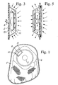
- Figure 1 shows a planar view of the currently preferred embodiment of a bag according to the invention seen from the distal wall, wherein the venting aperture is arranged,
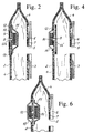
- Figure 2 shows a diagrammatical cross-sectional view of the upper region of the bag in Figure 1 having a filter assembly package according to the invention adhered to the inner surface of the distal wall,
- Figure 3 shows an enlarged diagrammatical cut away cross-sectional view of the filter assembly in Fig. 1 indicating the flow of flatus gas,
- Figure 4 shows a diagrammaticel cross-sectional view of the upper region of an alternative embodiment of a bag according to the invention having an alternative embodiment of a filter assembly package according to the invention adhered to the outer surface of the distal wall,
- Figure 5 shows an enlarged diagrammatical cut away cross-sectional view of the filter assembly in Fig. 4 indicating the flow of flatus gas,
- Figure 6 shows a view corresponding to Figs. 2 and 4 of a double filter assembly having filter packages adhered to both the outer and inner surface of the distal wall of a bag according to the invention,
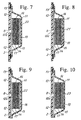
- Figures 7-10 show four alternative embodiments of a filter assembly according to the invention comprising four different embodiments of spacer means between the filter pad and the barrier membrane, and
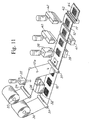
- Figure 11 shows a diagrammatical schematical elevational view of an application apparatus for producing a filter assembly according to the invention.
-
- It should be noted that for the sake of clarity and illustration of the constructive details, the relative dimensions of the elements in Figs. 2-11 are not correct, and the shapes and locations of the various elements relative to one another are distorted relative to reality where the films and elements conform much more to one another than as depicted.
- Referring now to Figs. 1-3, a bag or pouch 1 is defined by two bag sheets heat sealed or welded together at the edges thereof and constituting a
distal wall 2 and aproximal wall 3 of the bag 1. The bag sheets are made of five layers of film with a PVDC film sandwiched between two pairs of preferably EVA and/or PE film such that suitable gas and liquid impermeable heat sealablethermoplastic walls - A
backing layer 4 of soft linen, felt or the like is attached to the outer surface of the distal andproximal walls - The
proximal wall 3 is provided with astoma aperture 5 surrounded by a skinfriendly adhesion plate 6 for adhering the bag 1 to a patient and heat sealed at 7 to theproximal wall 3. Thedistal wall 2 is provided with aventing aperture 8 for venting flatus gasses from the interior of the bag 1 to the surroundings. - A heat sealed area indicated at 9 is provided in the
backing layer 4 surrounding theventing aperture 8 so as to provide a suitably smooth surface for temporarily adhering a tear-off tab for closing theventing aperture 8 for preventing flow of water into the bag 1 through theaperture 8 when a patient wearing the bag 1 takes a bath. - A filter assembly package or unit comprises an activated
carbon filter pad 10 sandwiched between abarrier membrane 11 of ultra high molecular weight polyethylene (UPE) and an approx. 100 micrometresthick support film 12 of polyethylene with 10 % EVA having aventing aperture 12a with a diameter of approx. 5 mm. The filter assembly package is heat sealed to the inner surface ofpouch wall 2 at 13. - Referring now to Figs. 7-10, the
filter pad 10 is a 20x20 mm2 100% active charcoal filter of the type FM7/250 supplied by Charcoal Cloth, UK having a thickness of approx. 1.3 mm. The charcoal textile consists of carbonized, woven viscose rayon textile. The carbonization takes place by means of a non-stochiometric process (low oxygen atmosphere to avoid burning of the material) at a temperature of 800-1000 degrees Celsius. The textile material of the pad consists of four layers interwoven in pairs, the pairs oflayers permeable layer 16 of adhesive of polyurethane or EVA configured as a porous net. - The charcoal filter is impregnated with a 5% w/w solution of copper so as to obtain a more rapid and better adsorption of flatus gasses as well as with a 5% w/w solution of fluor to bind/retain the carbon particles in the material i.a. to avoid carbon dust.
- The
charcoal layers films film 17 is gas permeable and consists of a PE nonwoven material adhered to thecharcoal layer 14 by means of an EVA adhesive configured as a porous net, while thefilm 18 is gas impermeable and consists of a material containing PVDC adhered to thecharcoal layer 15 by means of an EVA adhesive. - The charcoal filter is not or only partly liquid repelling in itself, but it is extremely efficient as a de-odorizing filter. The carbonised textile layers contain 0.16-0.18 g carbon (dry) and according to the modified British Standard testing method BS 7120, the filter adsorbs more than 30-40 I gas mixture, 30 ppm H2S in N2. A corresponding test with (CH3)2S shows that the filter can adsorb more than 40-60 l gas mixture, 30 ppm (CH3)2S in N2. The filter has a back pressure of max. 4.5 mBar with a gas flow therethrough of 100 ml/min at a pressure of 0.1 Bar. This low back pressure allows the flatus gasses to flow relatively quickly through the filter, thus avoiding ballooning of the bag 1.
- The ultra high molecular weight
polyethylene barrier membrane 11 is supplied by Millipore Corporation, Bedford, Mass., USA and is according to US patent No. 4,778,601. It has a pore volume of 70-80% and such that substantially all particles in the flatus gasses with a maximum dimension of 0.45 micrometres cannot pass through the barrier membrane, i.e. are retained thereby such that such particles cannot pass to thefilter pad 10 from the interior of the pouch 1. The thickness of thebarrier membrane 11 is 148 micrometres plus/minus 20 micrometres. The size is approx. 32x32 mm. The Flow Time is in the range of approx. 150 sec/500 ml to approx. 300 sec/500 ml in 100% IPA (applied to a circular membrane with a diameter of 47 mm at a pressure of 0.98 Bar (14.2 psi). Porosity determined by the Bubble Point Method is in the range of approx. 1.03 Bar (15 psi) to approx. 1.45 Bar (21 psi) in 100% IPA. - The
support film 12 is wider than the filter pad and is heat sealed or adhered to thefilm 17 of thefilter pad 10 such that theaperture 12a is centrally located relative to the filter pad. - The
film 17 of thefilter pad 10 is heat sealed/adhered to thesupport film 12 such that a circular non-sealed or non-adhered area of the filter pad larger than the5mm aperture 12a is centrally located around theaperture 12a. Thebarrier membrane 11 is arranged over thefilter pad 10 on the opposite side and is heat sealed/adhered to thesupport film 12 so that thefilter pad 10 is enclosed in a package comprising on one side a gas permeable, liquidimpermeable membrane 11 and on the other side a heat sealablePE support film 12 with acentral venting aperture 12a. - The filter package may thereafter be attached to the
bag wall 2 in which aventing aperture 8 smaller thanaperture 12a has been punched. The attachment to the inner surface of thewall 2 may either be accomplished by rim welding/heat sealing of thesupport film 12/membrane 11 to thewall 2 at 13 or by adhering the package to saidwall 2 with a suitable adhesive. - The
UPE membrane 11 has a smooth, soft surface and the surface tension has been measured to be 36 mN/m according to ISO 8296 (1987), while contact angle measurements according to the Wihelmy Plate Technique show that the surface of the membrane is similar to Teflon as regards friction. Therefore the ability of the membrane surface to repel liquid is such that a film of liquid preventing gas from passing through the membrane is not formed on the surface thereof. The pore volume of the membrane material of 70-80% and the structure (see Figs. 12-16) with very narrow passages only allowing particles smaller than 0.45 micrometres to pass therethrough entails that the flatus gas easily may pass through while human intestinal or fecal bacteria in the flatus gas or feces are retained by themembrane 11. - Furthermore, liquids are prevented from flowing through the membrane. Laboratory measurements where the membrane was loaded with 700 mm water column showed that no water flowed through, and no droplets were formed on the surface even after a test duration of 8 days.
- An Artificial Stool Test (Applicants' test method) consisting in filling bags 1 with artificial stool and inverting the bags so that the filter assembly was covered by artificial stool during 24 hours while observing whether artificial stool passed through the membrane gave excellent results. The artificial stool is composed of beans, salts, intestinal enzymes and other substances equivalent to the contents of the human intestine such that the test simulates the influences on the membrane in practice.
- The
barrier membrane 11 has a back pressure of approx. 2-3 mBar with an air flow therethrough of 100 ml/min at a pressure of 0.1 Bar. - Referring now to Fig. 3, the gas flow through the filter assembly is indicated by means of arrows, the gas flowing through the
membrane 11 and into thefilter pad 10 from the periphery thereof towards the centre thereof and out through theaperture 8 in thewall 2. - Referring now to Figs. 4-5, an alternative arrangement of the filter assembly on the outer surface of the
wall 2 is shown, the same references indicating the same elements as in Fig. 2. Thefilter pad 10 is adhered to the outer surface of the wall centrally located around the ventingaperture 8. A barrier membrane 14' of UPE material identical to the material ofbarrier membrane 11 in Fig. 2 is heat sealed or welded with thesupport film 12 to the inner surface of thewall 2. Thefilter pad 10 is covered by a protection membrane 15' of a gas permeable, liquid impermeable material that may be the same UPE material as the material of the membrane 14' or any other suitable material. The flow of flatus gasses through the filter assembly is indicated by the arrows in Fig. 5. - Referring now to Fig. 6, another alternative embodiment of a filter assembly according to the invention combining the embodiments of Figs. 2 and 4 is shown.
- It will be obvious to those skilled in the art that other filter designs may be employed and that the location and number of filter pads may be varied relative to the venting aperture. Furthermore, several venting apertures may be arranged in the
wall 2 combined with one or more filter pads. - Referring now again to Figs 7-10, various embodiments of spacing means arranged between the
filter pad 10 and thebarrier membrane 11 are illustrated, the spacing means ensuring a gas flow space between thefilter pad 10 and thebarrier membrane 11. In Fig. 7 ridges orpeaks 20 are formed in the surface of thefilm 18 or applied thereto. In Fig. 8 ridges orpeaks 21 are formed in the surface of thebarrier membrane 11 or applied thereto. In Fig. 9 filaments orspheres 22 are adhered to either thefilm 18 or themembrane 11. In Fig. 10 a layer of open cell foam material is adhered to either thefilm 18 or themembrane 11. In all embodiments it is obtained that substantially the entire area of thebarrier membrane 11 is available for flow of flatus gasses to thefilter pad 10. - Referring now to Fig. 11, an apparatus for producing a filter assembly according to the invention and as shown in Fig. 2 is shown schematically and diagrammatically.
- A
supply roll 30 of thebarrier membrane 11 feeds the membrane in a continuous web over anidler roller 31 below a locatingdevice 32 for locatingfilter pads 10 on the membrane web with a predetermined spacing. Asecond supply roll 33 of thesupport film 12 feeds the support film in a continuous web over anidler roller 34 below apunching device holes 12a in the support film spaced corresponding to the spacing of thefilter pads 10. The punched support film continues over anidler roller 37 such that the support film is superimposed on themembrane 11 and thefilter pads 10 with theholes 12a centrally located relative to thepads 10. - A
heat sealing device support film 12 to the gasimpermeable film 17 of thefitter pad 10 and thereafter aheat sealing device 40 41 heat seals thesupport film 12 to themembrane 11 whereafter acutting device support film 12 andmembrane 11 in the middle of the heat seal performed by thedevice wall 2 of the bag 1. - The heat sealing is carried out carefully to avoid compression of the relatively brittle filter cloth, so as to avoid crushing same. The pressure exerted by the
device - It should be understood that while the shown and described pouch 1 is entirely closed by a total welding or heat sealing around the entire periphery, the pouch may also be of the type having a drainage aperture provided by not welding the lower edge regions at the two bag sheets to each other.
Claims (5)
- A bag or pouch (1) for receiving discharge from the human body, said bag comprising:characterized in thata distal wall (2) and a proximal wall (3), each of a gas and liquid impermeable, heat sealable or weldable thermoplastic material and having the edges thereof sealed together and defining the interior of the bag between the walls, the proximal wall having a stomal aperture (5), and one of the walls having a gas venting aperture (8) spaced from the stomal aperture,a filter (10) for de-odorizing gas vented through the gas venting aperture and arranged such that all the gas exiting the bag through the venting aperture flows through the filter,an intermediate barrier membrane (11) arranged intermediate the filter and the interior of the bag such that all the gas exiting the bag through the filter flows through the barrier membrane and for preventing liquids and solids in the interior of the bag from contacting the filter while allowing gas to flow through the barrier membrane from the interior of the bag to the filter,the barrier membrane being adhered, preferably by heat sealing or welding, to said one wall,the filter comprising a pad (10), a first surface of the pad facing the barrier membrane being covered by a gas impermeable film (18), preferably bonded thereto, such that the gas flow path through the filter pad extends to or from the circumferential edge thereof,the barrier membrane comprises an unlaminated microporous film of ultra high molecular weight polyethylene, andthe filter pad comprises at least two mutually superimposed layers (14, 15) of textile being highly, preferably nearly 100%. carbonized, each layer being bonded to an adjacent layer by means of a gas permeable adhesive film (16).
- A bag according to claim 1, wherein said film has a porosity substantially only allowing passage through the barrier membrane of particles in said gas flow having a maximum dimension smaller than 2 micrometres, preferably 1.9 micrometres, more preferably 1.8 micrometres, even more preferably 1.7 micrometres, further preferably 1.6 micrometres, further preferably 1.5 micrometres, further preferably 1.4 micrometres, further preferably 1.3 micrometres, further preferably 1.2 micrometres, further preferably 1.1 micrometres, further preferably 1.0 micrometres, further preferably 0.9 micrometres, further preferably 0.8 micrometres, further preferably 0.7 micrometres, further preferably 0.6 micrometres, further preferably 0.5 micrometres.
- A bag according to claim 1, wherein said film has a porosity substantially only allowing passage through the barrier membrane of particles in said gas flow having a maximum dimension smaller than 0.45 micrometres.
- A bag according to claim 1, wherein said film has a porosity substantially only allowing passage through the barrier membrane of particles in said gas flow having a maximum dimension smaller than 0.3 micrometres, preferably smaller than 0.2 micrometres.
- A bag according to any of the preceding claims, wherein spacing means are arranged between the filter and the barrier membrane so as to ensure a space therebetween for allowing a flow of gas in said space.
Priority Applications (2)
| Application Number | Priority Date | Filing Date | Title |
|---|---|---|---|
| EP04028919A EP1514528B1 (en) | 1999-05-11 | 2000-05-11 | Venting/filter assembly for venting flatus gasses |
| DK00610045T DK1051955T3 (en) | 1999-05-11 | 2000-05-11 | Ventilation / filter assembly, bag with this device and method for venting flatus gases |
Applications Claiming Priority (3)
| Application Number | Priority Date | Filing Date | Title |
|---|---|---|---|
| DKPA199900647 | 1999-05-11 | ||
| DK64799 | 1999-05-11 | ||
| US09/568,318 US6506184B1 (en) | 1999-05-11 | 2000-05-09 | Venting/filter assembly, bag incorporating same and method of venting flatus gasses |
Related Child Applications (1)
| Application Number | Title | Priority Date | Filing Date |
|---|---|---|---|
| EP04028919A Division EP1514528B1 (en) | 1999-05-11 | 2000-05-11 | Venting/filter assembly for venting flatus gasses |
Publications (3)
| Publication Number | Publication Date |
|---|---|
| EP1051955A2 EP1051955A2 (en) | 2000-11-15 |
| EP1051955A3 EP1051955A3 (en) | 2002-04-10 |
| EP1051955B1 true EP1051955B1 (en) | 2004-12-15 |
Family
ID=26064383
Family Applications (1)
| Application Number | Title | Priority Date | Filing Date |
|---|---|---|---|
| EP00610045A Expired - Lifetime EP1051955B1 (en) | 1999-05-11 | 2000-05-11 | Venting/filter assembly, bag incorporating same and method of venting flatus gasses |
Country Status (3)
| Country | Link |
|---|---|
| US (2) | US6506184B1 (en) |
| EP (1) | EP1051955B1 (en) |
| DK (1) | DK1051955T3 (en) |
Families Citing this family (46)
| Publication number | Priority date | Publication date | Assignee | Title |
|---|---|---|---|---|
| US6506184B1 (en) * | 1999-05-11 | 2003-01-14 | Dansac A/S | Venting/filter assembly, bag incorporating same and method of venting flatus gasses |
| CN1255308C (en) * | 2000-12-21 | 2006-05-10 | 北越制纸株式会社 | Filter material take-up product for air filter |
| JP2003010226A (en) * | 2001-06-29 | 2003-01-14 | Alcare Co Ltd | Excrement housing outfitting |
| DK175356B1 (en) | 2002-02-28 | 2004-09-06 | Coloplast As | An ostomy appliance |
| US20030187412A1 (en) * | 2002-03-29 | 2003-10-02 | Martin David A. | Odor absorbing device and method |
| US6926701B2 (en) * | 2002-07-01 | 2005-08-09 | The Proctor & Gamble Company | Disposable excreta management device |
| US6746514B2 (en) | 2002-08-08 | 2004-06-08 | Baxter International Inc. | Gas venting device and a system and method for venting a gas from a liquid delivery system |
| ATE458459T1 (en) | 2003-06-02 | 2010-03-15 | Hollister Inc | A SELF-ADHESIVE COUPLING RING FOR AN OSTOMY DEVICE |
| DK176027B1 (en) * | 2003-12-22 | 2005-12-19 | Hollister Inc | Adhesive face plate for securing ostomy bag to skin of ostomy patient has flatus gas passages extended between flexible plate and face plate coupling ring, that engages with coupler of ostomy bag, through filter |
| CN1802180B (en) * | 2003-06-10 | 2010-09-08 | 大研医器株式会社 | Storage container and medical suction device provided with the same |
| ATE439821T1 (en) * | 2003-12-22 | 2009-09-15 | Hollister Inc | OSTOMY DEVICE WITH INNER AND OUTER BAGS CONNECTED BY PEELING SEAMS AND FILTER FOR DEODORIZING FLAT |
| SG115600A1 (en) * | 2003-12-31 | 2005-10-28 | Megatech Scientific Pte Ltd | Respiratory mask with inserted spacer |
| CN100404009C (en) * | 2004-05-03 | 2008-07-23 | 科洛普拉斯特公司 | ostomy appliances |
| FR2873286B1 (en) * | 2004-07-21 | 2006-09-22 | Braun Medical Sas | DEGASSING EVENT FILTER AND BODY FLUID COLLECTION POUCH |
| US7326190B2 (en) * | 2005-05-25 | 2008-02-05 | Hollister Incorporated | Ostomy pouch and high performance deodorizing gas filter assembly therefor |
| US20070049880A1 (en) * | 2005-08-23 | 2007-03-01 | Bristol-Myers Squibb Company | Filter assembly for an ostomy device |
| NZ551481A (en) * | 2005-11-30 | 2008-08-29 | Bristol Myers Squibb Co | Controlled evacuation ostomy appliance |
| US7678091B2 (en) * | 2007-03-15 | 2010-03-16 | Longstaff Charles W | Colostomy bag |
| JP4423409B2 (en) * | 2007-05-02 | 2010-03-03 | アルケア株式会社 | Deodorizing filter and excreta containing device equipped with the same deodorizing filter |
| US10646370B2 (en) * | 2008-04-01 | 2020-05-12 | Donaldson Company, Inc. | Enclosure ventilation filter and assembly method |
| US8979811B2 (en) * | 2008-04-01 | 2015-03-17 | Donaldson Company, Inc. | Enclosure ventilation filter and assembly method |
| US7981099B2 (en) * | 2008-07-10 | 2011-07-19 | Hollister Incorporated | Deodorizing gas filter assembly for a body waste collection pouch, and method of making |
| US20100140162A1 (en) * | 2008-10-24 | 2010-06-10 | Juzer Jangbarwala | Osmosis membrane with improved flux rate and uses thereof |
| WO2010060115A1 (en) | 2008-11-19 | 2010-05-27 | Convatec Technologies Inc. | Ostomy pouch appliance |
| US8468635B2 (en) * | 2009-11-25 | 2013-06-25 | Church & Dwight Co., Inc. | Surface treating device |
| US9102465B2 (en) * | 2010-01-22 | 2015-08-11 | Gail Elizabeth Davis | Container and method for storing animal waste and controlling associated odor |
| US9199013B2 (en) * | 2010-06-16 | 2015-12-01 | Simex Medizintechnik Gmbh | Device for wound treatment and a wound covering bandage or dressing |
| US8460259B2 (en) * | 2010-11-02 | 2013-06-11 | Convatec Technologies, Inc. | Controlled discharge ostomy appliance and moldable adhesive wafer |
| CN103200910B (en) * | 2010-11-08 | 2016-07-06 | 科洛普拉斯特公司 | There is the ostomy bag of intermediate filter element |
| CN102727345B (en) * | 2011-03-30 | 2014-08-20 | 韩富 | Absorptive article with super air permeability |
| HUE062325T2 (en) * | 2012-10-23 | 2023-10-28 | Coloplast As | Ostomy bag |
| GB2512655B (en) * | 2013-04-05 | 2017-10-25 | Salts Healthcare Ltd | Ostomy appliance |
| ES2931311T3 (en) | 2013-07-23 | 2022-12-28 | Convatec Technologies Inc | Moldable adhesive discs |
| US9993364B2 (en) | 2013-09-26 | 2018-06-12 | 3 West C, Llc | Ostomy bag |
| WO2015048446A1 (en) | 2013-09-26 | 2015-04-02 | 3 West C, Llc | Ostomy bag |
| US11298257B2 (en) * | 2017-03-22 | 2022-04-12 | 3 West C, Llc. | Ostomy apparatuses and related methods |
| GB201715388D0 (en) * | 2017-09-22 | 2017-11-08 | Salts Healthcare Ltd | An ostomy appliance |
| GB2566721B (en) * | 2017-09-22 | 2020-07-15 | Salts Healthcare Ltd | An ostomy appliance |
| US20220125617A1 (en) * | 2018-07-10 | 2022-04-28 | Hollister Corporation | Ostomy pouch filter |
| WO2020150504A1 (en) * | 2019-01-16 | 2020-07-23 | De La Vega Sanchez De Lozada Rafael | Anti-bacterial and deodorizing athletic bag |
| GB201903774D0 (en) * | 2019-03-20 | 2019-05-01 | Smith & Nephew | Negative pressure wound treatment apparatuses and methods with integrated electronics |
| US20220354684A1 (en) * | 2019-09-10 | 2022-11-10 | Advanced Medical Balloons Gmbh | Apparatus for continuously removing gas through a natural or artificial opening in the body of a patient |
| DK4120969T3 (en) * | 2020-03-20 | 2024-03-25 | Hollister Inc | STOMY BAG INCLUDING MULTI-STAGE FILTER PROTECTION |
| WO2021202314A1 (en) * | 2020-03-30 | 2021-10-07 | Donaldson Company, Inc. | Ostomy bag filter |
| GB202008258D0 (en) * | 2020-06-02 | 2020-07-15 | Convatec Ltd | An ostomy pounch |
| GB2626947A (en) * | 2023-02-07 | 2024-08-14 | Salts Healthcare Ltd | Ostomy appliance including a filter |
Family Cites Families (25)
| Publication number | Priority date | Publication date | Assignee | Title |
|---|---|---|---|---|
| US4274848A (en) | 1979-09-24 | 1981-06-23 | Hollister Incorporated | Gas-venting filter for collection appliance |
| US4419100A (en) * | 1982-03-16 | 1983-12-06 | Hollister Incorporated | Ostomy appliance and faceplate attachment therefor |
| GB2139501B (en) | 1983-04-14 | 1987-01-28 | Craig Med Prod Ltd | Ostomy bag, particularly for ileostomy patients |
| GB2149306B (en) | 1983-11-11 | 1987-02-18 | Craig Med Prod Ltd | Ostomy bag |
| US4778601A (en) | 1984-10-09 | 1988-10-18 | Millipore Corporation | Microporous membranes of ultrahigh molecular weight polyethylene |
| GB8503749D0 (en) * | 1985-02-14 | 1985-03-20 | Craig Med Prod Ltd | Gas filter |
| EP0283612A1 (en) * | 1987-03-16 | 1988-09-28 | Marlen Manufacturing and Development Company | A deodorizing ostomy pouch |
| NZ227995A (en) | 1988-03-07 | 1991-12-23 | Squibb & Sons Inc | Ostomy bag with filter: intervening wall has scattered holes |
| US5085652A (en) * | 1989-06-16 | 1992-02-04 | E. R. Squibb & Sons | Pouch with mounting member for removable adhesive filter |
| US5167650A (en) * | 1989-06-16 | 1992-12-01 | E. R. Squibb | Pouch with mounting member for removable adhesive filter |
| US4983171A (en) * | 1989-07-14 | 1991-01-08 | W. R. Grace & Co.-Conn. | Comfortable ostomy pouch |
| US5250042A (en) | 1990-02-20 | 1993-10-05 | E. R. Squibb & Sons, Inc. | Ostomy bag with filter combination |
| AU649827B2 (en) | 1991-02-28 | 1994-06-02 | Seiji Kagawa | Porous film, method for manufacturing the same, gas permeability control film, and water vapor permeability control film |
| FI89426C (en) | 1991-10-16 | 1993-09-27 | Telenokia Oy | Cable entry and grounding piece |
| US5370638A (en) * | 1992-12-22 | 1994-12-06 | E. R. Squibb & Sons, Inc. | Ostomy pouch |
| US5306264A (en) | 1993-01-14 | 1994-04-26 | E. R. Squibb & Sons, Inc. | Ostomy bag with multi-stage filter |
| US5401264A (en) * | 1994-04-18 | 1995-03-28 | Hollister Incorporated | Ostomy pouch with internal squeeze-to-open vent valve |
| US5417678A (en) * | 1994-07-15 | 1995-05-23 | Minnesota Mining And Manufacturing Company | Low profile ostomy filter |
| GB2296660B (en) | 1994-09-13 | 1998-06-17 | Welland Medical Ltd | Flatus filters |
| US5643234A (en) * | 1995-02-01 | 1997-07-01 | E. R. Squibb & Sons, Inc. | Ostomy bag with multi-stage filter |
| US5468235A (en) * | 1995-03-06 | 1995-11-21 | Hollister Incorporated | Ostomy pouch and filter assembly with successive flap vents |
| US5672163A (en) | 1996-04-26 | 1997-09-30 | Bristol-Myers Squibb Company | Ostomy pouch with intervening membrane and superabsorbent |
| US5690623A (en) | 1997-01-13 | 1997-11-25 | Dansac A/S | Vented ostomy pouch with protected gas filter |
| US6506184B1 (en) * | 1999-05-11 | 2003-01-14 | Dansac A/S | Venting/filter assembly, bag incorporating same and method of venting flatus gasses |
| JP2000333982A (en) * | 1999-05-27 | 2000-12-05 | Keiji Shiina | Deodorizing tool of pouch for artificial anus |
-
2000
- 2000-05-09 US US09/568,318 patent/US6506184B1/en not_active Expired - Lifetime
- 2000-05-11 EP EP00610045A patent/EP1051955B1/en not_active Expired - Lifetime
- 2000-05-11 DK DK00610045T patent/DK1051955T3/en active
-
2002
- 2002-12-13 US US10/319,770 patent/US6695826B2/en not_active Expired - Lifetime
Also Published As
| Publication number | Publication date |
|---|---|
| DK1051955T3 (en) | 2005-04-25 |
| EP1051955A2 (en) | 2000-11-15 |
| US6506184B1 (en) | 2003-01-14 |
| US20030100870A1 (en) | 2003-05-29 |
| EP1051955A3 (en) | 2002-04-10 |
| US6695826B2 (en) | 2004-02-24 |
Similar Documents
| Publication | Publication Date | Title |
|---|---|---|
| US6506184B1 (en) | Venting/filter assembly, bag incorporating same and method of venting flatus gasses | |
| US5250042A (en) | Ostomy bag with filter combination | |
| JP3933250B2 (en) | Ostomy pouch with intervening membrane and superabsorbent | |
| EP0130019B1 (en) | Ostomy pouch with deodorizing filter | |
| CA1146874A (en) | Gas-venting filter for collection appliance | |
| CA1153318A (en) | Surgical drainage bags | |
| EP0981311B1 (en) | An ostomy appliance | |
| US7341578B2 (en) | Ostomy appliance with multiple openings for preventing filter input blockage | |
| CN101990455B (en) | Hood ventilation filter and method of assembly thereof | |
| US5643234A (en) | Ostomy bag with multi-stage filter | |
| WO2015110544A1 (en) | Ostomy bag filter with adhesive webbing | |
| EP1514528B1 (en) | Venting/filter assembly for venting flatus gasses | |
| EP0235928B1 (en) | Deodorizing filters for ostomy equipment | |
| RU2384311C2 (en) | Filter with outgassing aperture and physiological fluid collection bag | |
| MXPA97002898A (en) | Ostomia sack with super absorbent membrane einterme |
Legal Events
| Date | Code | Title | Description |
|---|---|---|---|
| PUAI | Public reference made under article 153(3) epc to a published international application that has entered the european phase |
Free format text: ORIGINAL CODE: 0009012 |
|
| AK | Designated contracting states |
Kind code of ref document: A2 Designated state(s): AT BE CH CY DE DK ES FI FR GB GR IE IT LI LU MC NL PT SE |
|
| AX | Request for extension of the european patent |
Free format text: AL;LT;LV;MK;RO;SI |
|
| PUAL | Search report despatched |
Free format text: ORIGINAL CODE: 0009013 |
|
| AK | Designated contracting states |
Kind code of ref document: A3 Designated state(s): AT BE CH CY DE DK ES FI FR GB GR IE IT LI LU MC NL PT SE |
|
| AX | Request for extension of the european patent |
Free format text: AL;LT;LV;MK;RO;SI |
|
| 17P | Request for examination filed |
Effective date: 20021010 |
|
| AKX | Designation fees paid |
Free format text: AT BE CH CY DE DK ES FI FR GB GR IE IT LI LU MC NL PT SE |
|
| 17Q | First examination report despatched |
Effective date: 20030428 |
|
| GRAP | Despatch of communication of intention to grant a patent |
Free format text: ORIGINAL CODE: EPIDOSNIGR1 |
|
| GRAS | Grant fee paid |
Free format text: ORIGINAL CODE: EPIDOSNIGR3 |
|
| GRAA | (expected) grant |
Free format text: ORIGINAL CODE: 0009210 |
|
| AK | Designated contracting states |
Kind code of ref document: B1 Designated state(s): AT BE CH CY DE DK ES FI FR GB GR IE IT LI LU MC NL PT SE |
|
| PG25 | Lapsed in a contracting state [announced via postgrant information from national office to epo] |
Ref country code: NL Free format text: LAPSE BECAUSE OF FAILURE TO SUBMIT A TRANSLATION OF THE DESCRIPTION OR TO PAY THE FEE WITHIN THE PRESCRIBED TIME-LIMIT Effective date: 20041215 Ref country code: CH Free format text: LAPSE BECAUSE OF FAILURE TO SUBMIT A TRANSLATION OF THE DESCRIPTION OR TO PAY THE FEE WITHIN THE PRESCRIBED TIME-LIMIT Effective date: 20041215 Ref country code: IT Free format text: LAPSE BECAUSE OF FAILURE TO SUBMIT A TRANSLATION OF THE DESCRIPTION OR TO PAY THE FEE WITHIN THE PRESCRIBED TIME-LIMIT;WARNING: LAPSES OF ITALIAN PATENTS WITH EFFECTIVE DATE BEFORE 2007 MAY HAVE OCCURRED AT ANY TIME BEFORE 2007. THE CORRECT EFFECTIVE DATE MAY BE DIFFERENT FROM THE ONE RECORDED. Effective date: 20041215 Ref country code: FI Free format text: LAPSE BECAUSE OF FAILURE TO SUBMIT A TRANSLATION OF THE DESCRIPTION OR TO PAY THE FEE WITHIN THE PRESCRIBED TIME-LIMIT Effective date: 20041215 Ref country code: BE Free format text: LAPSE BECAUSE OF FAILURE TO SUBMIT A TRANSLATION OF THE DESCRIPTION OR TO PAY THE FEE WITHIN THE PRESCRIBED TIME-LIMIT Effective date: 20041215 Ref country code: AT Free format text: LAPSE BECAUSE OF FAILURE TO SUBMIT A TRANSLATION OF THE DESCRIPTION OR TO PAY THE FEE WITHIN THE PRESCRIBED TIME-LIMIT Effective date: 20041215 Ref country code: FR Free format text: LAPSE BECAUSE OF FAILURE TO SUBMIT A TRANSLATION OF THE DESCRIPTION OR TO PAY THE FEE WITHIN THE PRESCRIBED TIME-LIMIT Effective date: 20041215 Ref country code: LI Free format text: LAPSE BECAUSE OF FAILURE TO SUBMIT A TRANSLATION OF THE DESCRIPTION OR TO PAY THE FEE WITHIN THE PRESCRIBED TIME-LIMIT Effective date: 20041215 |
|
| REG | Reference to a national code |
Ref country code: CH Ref legal event code: EP Ref country code: GB Ref legal event code: FG4D |
|
| REG | Reference to a national code |
Ref country code: IE Ref legal event code: FG4D |
|
| REF | Corresponds to: |
Ref document number: 60016665 Country of ref document: DE Date of ref document: 20050120 Kind code of ref document: P |
|
| PG25 | Lapsed in a contracting state [announced via postgrant information from national office to epo] |
Ref country code: SE Free format text: LAPSE BECAUSE OF FAILURE TO SUBMIT A TRANSLATION OF THE DESCRIPTION OR TO PAY THE FEE WITHIN THE PRESCRIBED TIME-LIMIT Effective date: 20050315 Ref country code: GR Free format text: LAPSE BECAUSE OF FAILURE TO SUBMIT A TRANSLATION OF THE DESCRIPTION OR TO PAY THE FEE WITHIN THE PRESCRIBED TIME-LIMIT Effective date: 20050315 |
|
| PG25 | Lapsed in a contracting state [announced via postgrant information from national office to epo] |
Ref country code: ES Free format text: LAPSE BECAUSE OF FAILURE TO SUBMIT A TRANSLATION OF THE DESCRIPTION OR TO PAY THE FEE WITHIN THE PRESCRIBED TIME-LIMIT Effective date: 20050326 |
|
| REG | Reference to a national code |
Ref country code: DK Ref legal event code: T3 |
|
| PG25 | Lapsed in a contracting state [announced via postgrant information from national office to epo] |
Ref country code: IE Free format text: LAPSE BECAUSE OF NON-PAYMENT OF DUE FEES Effective date: 20050511 Ref country code: LU Free format text: LAPSE BECAUSE OF NON-PAYMENT OF DUE FEES Effective date: 20050511 Ref country code: CY Free format text: LAPSE BECAUSE OF FAILURE TO SUBMIT A TRANSLATION OF THE DESCRIPTION OR TO PAY THE FEE WITHIN THE PRESCRIBED TIME-LIMIT Effective date: 20050511 |
|
| PG25 | Lapsed in a contracting state [announced via postgrant information from national office to epo] |
Ref country code: MC Free format text: LAPSE BECAUSE OF NON-PAYMENT OF DUE FEES Effective date: 20050531 |
|
| NLV1 | Nl: lapsed or annulled due to failure to fulfill the requirements of art. 29p and 29m of the patents act | ||
| REG | Reference to a national code |
Ref country code: CH Ref legal event code: PL |
|
| PLBE | No opposition filed within time limit |
Free format text: ORIGINAL CODE: 0009261 |
|
| STAA | Information on the status of an ep patent application or granted ep patent |
Free format text: STATUS: NO OPPOSITION FILED WITHIN TIME LIMIT |
|
| 26N | No opposition filed |
Effective date: 20050916 |
|
| EN | Fr: translation not filed | ||
| REG | Reference to a national code |
Ref country code: IE Ref legal event code: MM4A |
|
| PG25 | Lapsed in a contracting state [announced via postgrant information from national office to epo] |
Ref country code: PT Free format text: LAPSE BECAUSE OF NON-PAYMENT OF DUE FEES Effective date: 20050515 |
|
| PGFP | Annual fee paid to national office [announced via postgrant information from national office to epo] |
Ref country code: DK Payment date: 20170530 Year of fee payment: 18 Ref country code: GB Payment date: 20170530 Year of fee payment: 18 Ref country code: DE Payment date: 20170530 Year of fee payment: 18 |
|
| REG | Reference to a national code |
Ref country code: DE Ref legal event code: R119 Ref document number: 60016665 Country of ref document: DE |
|
| REG | Reference to a national code |
Ref country code: DK Ref legal event code: EBP Effective date: 20180531 |
|
| GBPC | Gb: european patent ceased through non-payment of renewal fee |
Effective date: 20180511 |
|
| PG25 | Lapsed in a contracting state [announced via postgrant information from national office to epo] |
Ref country code: GB Free format text: LAPSE BECAUSE OF NON-PAYMENT OF DUE FEES Effective date: 20180511 Ref country code: DE Free format text: LAPSE BECAUSE OF NON-PAYMENT OF DUE FEES Effective date: 20181201 |
|
| PG25 | Lapsed in a contracting state [announced via postgrant information from national office to epo] |
Ref country code: DK Free format text: LAPSE BECAUSE OF NON-PAYMENT OF DUE FEES Effective date: 20180531 |