EP1051906A2 - Dual-bearing reel braking device - Google Patents
Dual-bearing reel braking device Download PDFInfo
- Publication number
- EP1051906A2 EP1051906A2 EP00303963A EP00303963A EP1051906A2 EP 1051906 A2 EP1051906 A2 EP 1051906A2 EP 00303963 A EP00303963 A EP 00303963A EP 00303963 A EP00303963 A EP 00303963A EP 1051906 A2 EP1051906 A2 EP 1051906A2
- Authority
- EP
- European Patent Office
- Prior art keywords
- braking
- spool
- rotary member
- members
- spindle
- Prior art date
- Legal status (The legal status is an assumption and is not a legal conclusion. Google has not performed a legal analysis and makes no representation as to the accuracy of the status listed.)
- Granted
Links
- 230000009977 dual effect Effects 0.000 title claims abstract description 21
- 230000007246 mechanism Effects 0.000 claims abstract description 103
- 230000008878 coupling Effects 0.000 claims abstract description 44
- 238000010168 coupling process Methods 0.000 claims abstract description 44
- 238000005859 coupling reaction Methods 0.000 claims abstract description 44
- 238000005266 casting Methods 0.000 claims description 22
- 230000002093 peripheral effect Effects 0.000 claims description 9
- 239000011435 rock Substances 0.000 claims description 2
- 210000003813 thumb Anatomy 0.000 description 14
- 230000008859 change Effects 0.000 description 5
- 230000005484 gravity Effects 0.000 description 5
- 238000004804 winding Methods 0.000 description 2
- 230000004323 axial length Effects 0.000 description 1
- 230000003247 decreasing effect Effects 0.000 description 1
- 238000010586 diagram Methods 0.000 description 1
- 230000000694 effects Effects 0.000 description 1
- 230000004048 modification Effects 0.000 description 1
- 238000012986 modification Methods 0.000 description 1
Images



Classifications
-
- A—HUMAN NECESSITIES
- A01—AGRICULTURE; FORESTRY; ANIMAL HUSBANDRY; HUNTING; TRAPPING; FISHING
- A01K—ANIMAL HUSBANDRY; AVICULTURE; APICULTURE; PISCICULTURE; FISHING; REARING OR BREEDING ANIMALS, NOT OTHERWISE PROVIDED FOR; NEW BREEDS OF ANIMALS
- A01K89/00—Reels
- A01K89/015—Reels with a rotary drum, i.e. with a rotating spool
- A01K89/0155—Antibacklash devices
-
- A—HUMAN NECESSITIES
- A01—AGRICULTURE; FORESTRY; ANIMAL HUSBANDRY; HUNTING; TRAPPING; FISHING
- A01K—ANIMAL HUSBANDRY; AVICULTURE; APICULTURE; PISCICULTURE; FISHING; REARING OR BREEDING ANIMALS, NOT OTHERWISE PROVIDED FOR; NEW BREEDS OF ANIMALS
- A01K89/00—Reels
- A01K89/02—Brake devices for reels
- A01K89/033—Brake devices for reels with a rotary drum, i.e. for reels with a rotating spool
-
- A—HUMAN NECESSITIES
- A01—AGRICULTURE; FORESTRY; ANIMAL HUSBANDRY; HUNTING; TRAPPING; FISHING
- A01K—ANIMAL HUSBANDRY; AVICULTURE; APICULTURE; PISCICULTURE; FISHING; REARING OR BREEDING ANIMALS, NOT OTHERWISE PROVIDED FOR; NEW BREEDS OF ANIMALS
- A01K89/00—Reels
- A01K89/015—Reels with a rotary drum, i.e. with a rotating spool
- A01K89/0155—Antibacklash devices
- A01K89/01557—Centrifugal
Definitions
- the present invention relates to braking devices, in particular to braking devices on dual-bearing reels for braking the spool in a dual-bearing reel.
- braking force is made to act on the spool so that backlash, wherein the rotational speed of the spool when casting is faster than the line wind-out speed, does not occur.
- centrifugal braking mechanisms that employ centrifugal force developing from spool rotation to brake the spool, and casting control mechanisms that mechanically brake the spool shaft by grasping either end of the spool spindle are known.
- Japanese Laid-Open Pat. App. No. 10-304798 discloses a centrifugal braking mechanism in this class of braking device, wherein the braking force is adjustable from the outer side of the reel body.
- the centrifugal braking mechanism is furnished with a rotary member that rotates linked with the spool; a plurality of braking members disposed in radial fashion on the rotary member; a stationary member that comes into contact with the tips of the braking members; and a braking force adjustment mechanism.
- the braking members of the plurality are fitted to, and pivotable around axes along chord directions of, the rotating member; by centrifugal force they pivot within planes that pass through the axis of the spool.
- the stationary member is non-rotatably fitted to the reel body but able to travel in the spool spindle direction, and can come into contact with braking members that have rocked due to centrifugal force.
- a mechanism that shifts the stationary member back and forth in the spool spindle direction, the braking force adjustment mechanism is for adjusting braking force that contacting of the braking members on the stationary member generates.
- Casting control mechanisms are furnished with friction plates disposed on either end of, as a pair sandwiching, the spool spindle, and a cap provided screw-mated to the reel body in order to regulate the grasping force by the friction plates.
- the spool shaft is braked by turning the cap, which presses the spool spindle more towards the friction plate on the other end than the friction plate on the one end.
- the spool spindle shifts slightly when adjusting the braking force with the casting control mechanism.
- the spool shaft shifts, this accompanied by the rotary member of the centrifugal braking mechanism also shifting axially, along with its braking members.
- An object of the present invention is to facilitate, and enable to be accurately performed the operation of adjusting the braking force in dual-bearing reel braking devices.
- the braking device for a dual-bearing reel as determined by a first aspect of the present invention is a device for braking a spool which is provided with a reel body of the dual-bearing reel and includes a rotating member, a plurality of braking members, a fixing member, a coupling means, and a braking force adjusting means.
- the rotating member is rotatably provided with the reel body in a non-movable manner in an axial direction.
- the plurality of braking members is movably provided with the rotating member and moved by a centrifugal force.
- the fixing member is non-rotatably provided with the reel body in a movable manner in the axial direction.
- the fixing member when moved in the axial direction, is capable of making contact with the braking members, which are moved by a centrifugal force, in a different frictional state.
- the coupling means is a means for non-rotatably coupling the rotating member to an interlocking member which interlocks with the spool in a movable manner in the axial direction.
- the braking force adjusting means is a means for adjusting a braking force. The braking force adjusting means moves the fixing member in the axial direction and adjusts a braking force which is generated when the fixing member is moved in the axial direction and makes contact with the braking members.
- the interlocking members including the spool shaft and the spool itself rotate together with the spool, and the rotating member which is non-rotatably coupled to the interlocking members by the coupling means rotates together with the spool.
- the rotating member rotates
- the braking members move towards the fixing member by a centrifugal force.
- a braking force is applied to the rotating member due to friction between the braking members and the fixing member, and the spool is braked.
- a friction state between the fixing member and the braking members becomes different depending on the position of the fixing member in the axial direction and the braking force applied varies accordingly.
- an adjustment of the braking force may be easily carried out by moving the fixing member in the axial direction of the rotating member by using the braking force adjusting means.
- the rotating member since the rotating member is rotatably provided with the reel body in a non-movable manner in the axial direction and coupled to the interlocking members by the coupling means in a movable manner in the axial direction, the rotating member does not move in the axial direction if the interlocking members such as the spool shaft are moved in the axial direction by fluctuation of the interlocking member or an operation of the casting control mechanism.
- the distance between the rotating member and the fixing member does not change unless the fixing member is intentionally moved. For this reason, a predetermined braking force is not changed if the interlocking members are moved and, hence, an adjustment of the braking force may be performed in an accurate manner.
- the braking device for a dual-bearing reel as determined by a second aspect of the invention is, in braking devices in the first aspect, one wherein the spool is non-rotatably coupled to a spool shaft which is the interlocking member and the coupling means is provided with the spool shaft and non-rotatably couples the rotating member to the spool shaft in a movable manner in the axial direction.
- the coupling means is provided with the spool shaft and non-rotatably couples the rotating member to the spool shaft in a movable manner in the axial direction.
- the rotating member does not move in the axial direction if the spool shaft is moved in the axial direction since the rotating member is coupled to the spool shaft by the coupling means in a movable manner in the axial direction. Accordingly, if the spool shaft is moved due to fluctuation of the spool shaft or an operation of the casting control mechanism, the braking force is not changed.
- the braking device for a dual-bearing reel as determined by a third aspect is, in braking devices in the first or second aspect, one wherein the fixing member has an inner surface of a cone shape which functions as a braking surface, the inner surface being disposed so as to face an outer periphery side of the rotating member and be concentric with the rotating member and the braking members are radially disposed so as to face the braking surface, each of the braking members being provided with the rotating member in a movable manner to a respective movement limit position and capable of making contact with the braking surface by a centrifugal force.
- the braking surface of the fixing member has a cone shape
- the diameter of a osculating circle formed by a contact of the braking members with the braking surface is reduced as the fixing member is moved towards the rotating member and, accordingly, the distance required for the braking members to move in order to make contact with the braking surface is shortened.
- the number of braking members which may make contact with the braking surface gradually increases since the braking member which has a movement limit position close to the rotating member becomes capable of making contact with the braking surface and, hence, the braking force is increased.
- the fixing member is moved away from the rotating member, the braking force is gradually decreased.
- the distance between the fixing member and the rotating member is not changed if the interlocking members are moved in the axial direction since the rotating member is not moved and, therefore, the diameter of the osculating circle does not change. For this reason, the braking force does not vary if the interlocking members are moved in the axial direction.
- the braking device for a dual-bearing reel as determined by a fourth aspect of the invention is, in braking devices in the third aspect, one wherein the braking members are provided with the rotating member so as to be movable in a direction substantially right angle to the braking surface.
- the braking members make contact with the braking surface substantially at right angle and a component of centrifugal force which is vertical to the braking surface becomes a vertical drag for generating friction for braking, a centrifugal force may be efficiently converted to a braking force.
- the braking device for a dual-bearing reel as determined by a fifth aspect of the present invention is, in braking devices in the third or fourth aspect, one wherein the fixing member includes a supporting portion non-rotatably supported by the reel body in a movable manner in an axial direction of the spool and a main portion integrally formed with the supporting portion, the main portion having the inner surface of cone shape which functions as the braking surface, and the braking force adjusting means includes a lever portion movably provided with the reel body, the lever portion being exposed to outside of the reel body and a converting mechanism for converting movement of the lever portion to a movement of the main portion in an axial direction of the spool.
- the braking force since the main portion of the fixing member which is supported by the reel body is moved in the axial direction when the lever portion which is exposed outside is moved, the braking force may be adjusted by a simple operation from outside.
- the braking device for a dual-bearing reel as determined by a sixth aspect is, in braking devices in the first or second aspect, one wherein the braking members are radially provided with the rotating member with a space between each other in a circumferential direction of the rotating member so as to be movable around an axis along a chord direction, their position of center of gravity being placed at a the spool side with respect to a center of movement, and the fixing member has an annular braking surface, the annular braking surface may make contact with an end portion of the braking members and is provided substantially right angle to a rotational axis of the rotating member.
- the end portion of the respective braking member which is movably provided with the rotating member moves towards the fixing member and makes contact with the fixing member to brake the spool.
- the braking force is determined by the angle of the braking members when they make contact with the fixing member.
- the rotating member is not affected by the movement. Accordingly, the angle of the braking members when they make contact with the fixing member is not changed.
- the braking force may be adjusted in an easy and accurate manner.
- the braking device for a dual-bearing reel as determined by a seventh aspect of the invention is, in braking devices in any of the first through sixth aspects, one that further comprises a casting control mechanism which is capable of braking the spool by holding the coupling member.
- a casting control mechanism which is capable of braking the spool by holding the coupling member.
- Fig. 1 is a plan view of a dual-bearing reel to which an embodiment according to the present invention is applied.
- the dual-bearing reel shown in the figure is a bait reel chiefly used for lure fishing and includes a reel body 1 , a handle 2 , and a star drag 3 for adjusting drag.
- the handle 2 is provided for rotating the spool and is disposed at one side of the reel body 1 .
- the star drag 3 is disposed on the reel-body side of the handle 2 .
- the handle 2 is of a double-grip type having a plate-type arm portion 2a and holding portions 2b , each of which is rotatably provided on respective ends of the arm portion 2a .
- the outer surface of the arm portion 2a of the handle 2 is a smooth seamless surface to keep fishing line from getting tangled on it.
- the reel body 1 includes a frame 5 , a first side-cover 6 , a second side-cover 7 , and a front cover 10 .
- the first side-cover 6 and the second side-cover 7 are disposed on respective sides of the reel frame 5 .
- the front cover 10 is disposed to be open/closable on a front portion of the frame 5 .
- the frame 5 includes a pair of side plates 8 and 9 , which are disposed opposite each other at a predetermined spacing, and a plurality of connecting members, each of which connects the side plates 8 and 9 .
- the second side-cover 7 which is located on the handle 2 side, is fixed to the side plate 9 by screws so that it may be detached from the side plate 9 .
- the first side-cover 6 which is located on the opposite side of the handle 2 , is detachably attached to the side plate 8 of the frame 5 .
- the first side-cover 6 includes a cover body 6a and a brake case 64 .
- the cover body 6a curves outwardly in a bowl shape, and the brake case 64 is fixed to the cover body 6a by screws.
- the brake case 64 will be described in detail later.
- the spool 12 , a level wind mechanism 15 , and a thumb rest 17 are disposed inside the frame 5 .
- the level wind mechanism 15 is provided for uniformly reeling in fishing line around the spool 12 .
- the thumb rest 17 is a pad for the thumb during a thumbing operation.
- a gear mechanism 18 , a clutch mechanism 13 , a clutch engage/release mechanism 19 , a drag mechanism 21 , and a casting control mechanism 22 are disposed in the space between the frame 5 and the second side-cover 7 .
- the gear mechanism 18 transmits rotational force from the handle 2 to the spool 12 and the level wind mechanism 15 .
- the clutch engage/release mechanism 19 switches the clutch mechanism 13 in accordance with the operation of the thumb rest 17 .
- a centrifugal braking mechanism 23 for preventing backlash during casting is provided between the frame 5 and the first side-cover 6 .
- the spool 12 on either side has dish-shaped flange portions 12a , and between the flange portions 12a has tubular line-winding trunk 12b . Also, the spool 12 has a tubular boss portion 12c that is formed integral with the inner peripheral side of the line-winding trunk 12b in the middle.
- a serration engagement the spool 12 is non-rotatably fixed to the spool spindle 16 , which penetrates through the boss portion 12c .
- the means for fixing the spool 12 to the spool spindle 16 is not limited to the serration engagement and various other means such as key coupling or spline coupling may be used.
- the spool spindle 16 penetrates the side plate 9 and extends outside the second side-cover 7 .
- the extended end of the spool spindle 16 is rotatably supported by bearing 35b of a boss portion 29 which is provided with the second side-cover 7 .
- bearing 35a in the centrifugal braking mechanism 23 rotatably supports the other end of the spool spindle 16 .
- the bearings 35a and 35b are shielded ball bearings.
- the spool spindle 16 has a central large-diameter portion 16a to which the spool 12 is fixed and two (right and left) small-diameter portions 16b and 16c , formed on either end of the large diameter portion 16a .
- the large-diameter portion 16a is disposed in a space within the spool body 12b of the spool 12 , and serrations 16d are formed on the outer surface of the middle of the large-diameter portion 16a , for fixing the spool 12 .
- a rotary member 66 of the centrifugal braking mechanism 23 is rotatably coupled to the periphery of the left small-diameter portion 16c to be axially movable.
- the bearing 35a supports the rotary member 66 in the brake case 64 .
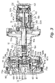
- a coupling pin 24 for coupling the rotary member 66 is fitted on the right end of the small-diameter portion 16c as shown in Fig. 3.
- the coupling pin 24 diametrically penetrates the right end of the small-diameter portion 16c and couples the rotary member 66 to the spool spindle 16 to be non-rotatable yet axially shiftable.
- the bearing 35a via the rotary member 66 rotatably supports the other end of the spool spindle 16 .
- a pinion gear 32 is supported on the right small-diameter portion 16b to be axially shiftable.
- the bearing 35b rotatably supports the end of the small-diameter portion 16b on the boss portion 29 .
- both ends of the spool spindle 16 are made superficially spherical to keep down increase in rotational resistance.
- the level wind mechanism 15 includes a guide tube 25 , a worm shaft 26 , and a line guide 27 .
- the guide tube 25 is fixed between the pair of side plates 8 and 9 .
- the worm shaft 26 is rotatably supported in the guide tube 25 .
- a gear 28a which forms a part of the gear mechanism 18 , is fixed to one end of the worm shaft 26 .
- a spiral groove 26a is formed on the worm shaft 26 , and the line guide 27 is meshed with the spiral groove 26a .
- the line guide 27 therefore reciprocates along the guide tube 25 by the worm shaft 26 being rotated via the gear mechanism 18 .
- a fishing line is inserted in the line guide 27 and uniformly wound onto the spool 12 .
- the gear mechanism 18 includes a main gear 31 , a pinion gear 32 , the above-mentioned gear 28a , and a gear 28b .
- the main gear 31 is fixed to a handle shaft 30 .
- the pinion gear 32 is cylindrical and is engaged with the main gear 31 .
- the gear 28a is fixed to one end of the worm shaft 26 .
- the gear 28b is non-rotatably fixed to the handle shaft 30 and engaged with the gear 28a .
- the pinion gear 32 is a cylindrical member whose center the spool spindle 16 penetrates, as shown in Fig. 3.
- the pinion gear 32 is coupled to the spool spindle 16 to be axially shiftable.
- the pinion gear 32 includes teeth 32a , a meshing portion 32b , and a constriction 32c as shown in Fig. 3.
- the teeth 32a are formed circumferentially on the right end of the pinion gear 32 and mesh with the main gear 31 .
- the meshing portion 32b is formed on the other side of the pinion gear 32 .
- the constriction 32c is provided between the teeth 32a and the meshing portion 32b .
- the meshing portion 32b includes an oblong cavity formed in the end face of the pinion gear 32 .
- the clutch mechanism 13 is constituted by the oblong cavity in the meshing portion 32b and the beveled portion 16e .
- the thumb rest 17 is disposed in the rear of the spool 12 between the pair of side plates 8 and 9 .
- the thumb rest 17 is also used as a clutch lever.
- An elongated hole (not shown) is formed in the side plates 8 and 9 of the frame 5 , and the thumb rest 17 is supported to be shiftable in the elongated hole. Thus, the thumb rest 17 slides up and down along the elongated hole.
- the clutch engage/release mechanism 19 includes a clutch yoke 40 as shown in Fig. 3. By turning movement of the thumb rest 17 , the clutch engage/release mechanism 19 shifts the clutch yoke 40 parallel to the axis of the spool spindle 16 . Further, when the handle shaft 30 is rotated in the line reeling-in direction, the clutch engage/release mechanism 19 shifts the clutch yoke 40 whereby the clutch mechanism 13 is automatically put on.
- the clutch yoke 40 is disposed about the outer periphery of the spool spindle 16 and is supported on two pins 41 (only one of them is shown in the figure) to be shiftable parallel to the axis of the spool spindle 16 .
- the spool spindle 16 is rotatable relative to the clutch yoke 40 . That is, this makes it so that the clutch yoke 40 does not rotate though the spool spindle 16 rotates. Also, in the middle of the clutch yoke 40 is an engaging portion 40a that is engaged in the constriction 32c of the pinion gear 32 . Moreover, a spring 42 is provided surrounding each of the pins 41 between the clutch yoke 40 and the second side-cover 7 . The clutch yoke 40 is always urged inward (i.e., clutch engagement-ward) by the spring 42 .
- the pinion gear 32 is normally situated in the inward clutch-engaging position wherein the meshing portion 32b is engaged with the beveled portion 16e of the spool spindle 16 , which is the clutch-on state.
- the clutch yoke 40 shifts the pinion gear 32 outward, the meshing portion 32b is disengaged from the beveled portion 16e , which is the clutch-off state.
- the drag mechanism 21 includes as shown in Fig. 2 a friction washer 45 that presses on the main gear 31 , and a pressing plate 46 for pressing, the friction washer 45 on the main gear 31 at a predetermined force by rotation of the star drag 3 .
- the casting control mechanism 22 includes as shown in Fig. 3 a plurality of friction plates 51 arranged sandwiching either end of the spool spindle 16 , and a cap 52 for adjusting the grasping force on the spool spindle 16 due to the friction plates 51 .
- the left-end friction plates 51 are fitted within the brake case 64 .
- the cap 52 is screw-mated with the circumferential surface of the boss portion 29 . In this casting control mechanism 22 , turning the cap 52 for example clockwise advances the cap 52 leftward in Fig. 3. This presses spool spindle 16 further against the friction plates 51 on the cap 52 end, and shifts slightly leftward in Fig.
- the centrifugal braking mechanism 23 is accommodated in the brake case 64 , configured in the first side-cover 6 .
- the brake case 64 is a short cylindrical member having a bottom configured in the reel body 1 .
- the brake case 64 may be fixed to the cover body 6a by using, for instance, two screws 75a and 75b , as the enlarged view in Fig. 3 shows.
- the brake case 64 is attachably/detachably fitted into the side plate 8 by a bayonet structure 14 at the circumference of a circular opening 8a formed in the side plate 8 for passing the spool 12 .
- the first side-cover 6 is removably attached to the side plate 8 .
- a cylindrically shaped bearing housing 64a protruding inward is formed in the center of the bottom of the brake case 64 .
- the bearing 35a for rotatably supporting the spool spindle 16 , and the rotary member 66 of the centrifugal braking mechanism 23 are accommodated in the bearing housing 64a .
- the friction plates 51 of the casting control mechanism 22 are fitted in a bottom surface formed intermediate axially in the bearing housing 64a .
- the centrifugal braking mechanism 23 includes: the rotary member 66 , supported in the bearing housing 64a to be rotatable yet axially immobile; a plurality of braking members 68 fitted on the rotary member 66 ; a stationary member 67 able to come into contact with the braking members 68 in different frictional states; the coupling pin 24 ; and a braking force adjusting mechanism 69 for adjusting braking force that develops from the braking members 68 contacting the stationary member 67 .
- the rotary member 66 is supported via the bearing 35a in the bearing housing 64a to be allowed to rotate yet be axially immobile.
- the rotary member 66 includes a rotor 71 coupled to the spool spindle 16 by the coupling pin 24 to be non-rotatable yet permit axial shift, and six, for example, guide shafts 72 in a radiating arrangement on the rotor 71 .
- the rotor 71 includes a cylindrical portion 71a allowed to rotate fitted circumferentially on the small diameter portion 16c of the spool spindle 16 yet axially immobile, and a guide anchor 71b fitted to the Fig. 3 right-end outer periphery of the cylindrical portion 71a to be both non-rotatable and axially immobile.
- the bearing 35a is fitted on the Fig. 3 left end of the cylindrical portion 71a .
- a large diameter portion is formed in the middle of the cylindrical portion 71a , sandwiched between the inner race of the bearing 35a and the guide anchor 71b .
- a pair of engaging grooves 71c into which the coupling pin 24 interlocks is formed on the right end of the cylindrical portion 71a .
- the axial length of the engaging groove 71c is longer than the diameter of the coupling pin 24 and an axial gap is formed between the bottom of the engaging groove 71c and the coupling pin 24 .
- the rotary member 66 therefore allows axial shift in the spool spindle 16 .
- the rotary member 66 thus is coupled by the coupling pin 24 to be non-rotatable with respect to the spool spindle 16 yet to permit axial shift, and moreover is allowed to rotate supported in the bearing housing 64a yet is axial immobile.
- the rotary member 66 therefore rotates linked with the spool 12 . Nevertheless, even with the spool spindle 16 shifting axially, the rotary member 66 does not shift.
- the guide anchor 71b includes a disk portion 71d and a shaft anchor 71e .
- the inner side of the disc plate portion 71d is non-rotatably fitted to the cylindrical portion 71a and is axially immobile.
- From the circumferential end of the disc plate portion 71d heading peripherally outward of the bearing housing 64a extends the shaft anchor 71e , inside which the guide shafts 72 are radially stood on their extended tips.
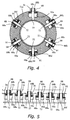
- the shaft anchor 71e is a thick, disk-shaped member and, as shown in Fig. 4, six regulator spaces 90a through 90f differing in length in the radial direction of the shaft anchor 71e are formed encompassing the stood sections of the guide shafts 72 .
- the guide shafts 72 are radially arranged in the centers of the regulator spaces 90a to 90f . Openings 91 in which the braking members 68 are shiftable are formed at the outer peripheral ends of the regulator spaces 90a to 90f .
- Each of the plurality of the braking members 68 is a cylindrical member having base-end collar 68a .
- the braking members 68 are fitted on the guide shafts 72 to permit radial travel and shift radially outward under centrifugal force.
- the collars 68a are furnished to interlock with the opening portions 91 , as shown in Fig. 5, when centrifugal force shifts the braking members 68 radially, to check any further radially outward shift.
- the braking members 68 thus can travel radially outward different distances.
- Contact faces 68b that contact on a brake liner 70 fitted to the stationary member 67 are formed on the tips of the braking members 68 .
- the contact faces 68b are slant surfaces conforming to the brake liner 70 .
- the diametrical length of the regulator space 90a to the opening 91 is set to a length at which the end of the braking member 68 shifted peripherally outward, when the stationary member 67 is in its retracted position parted furthest from the rotary member 66 , cannot contact on the brake liner 70 .
- the length of the regulator space 90f is set to a length at which the end of the braking member 68 shifted peripherally outward, when the stationary member 67 is in its advanced position, can contact on the brake liner 70 .
- the lengths of the middle regulator spaces 90b to 90e are then set to become shorter in even intervals, for example, in between.
- the stationary member 67 is a cylindrical component having a cylindrical portion 67a disposed peripherally outward of the rotary member 66 ; and a support portion 67b formed integrally with the cylindrical portion 67a on its inner periphery and supported by the bearing housing 64a to permit axial travel.
- the brake liner 70 is removably fitted to the inner peripheral surface of the cylindrical portion 67a , and has a tapered surface flaring forward towards the spool 12 .
- an interlock projection 67c protrudes diametrically.
- the interlock projection 67c is interlocked with an engagement groove 64b formed on the inner peripheral surface of the brake case 64 along the axial direction.
- the stationary member 67 is made non-rotatable with respect to the brake case 64 , i.e. to the reel body 1 .
- the support portion 67b is fitted to the bearing housing 64a to permit axial travel.
- a cam projection 92 which the braking force adjusting mechanism 69 comprises, is formed on the outward lateral surface of the support portion 67b .
- the cam projection 92 is an arc shaped protrusion, and the amount by which it projects gradually enlarges going one way circumferentially.
- the braking force adjusting mechanism 67 is a device for moving the stationary member 67 fore-and-aft (in the spool axial direction) and includes a knob 80 and a converting mechanism 81 .
- the knob 80 is supported in the brake case 64 to permit rotation.
- the converting mechanism 81 converts rotation of the knob 80 into a fore-and-aft advancing movement of the stationary member 67 .
- the knob 80 is partially exposed outside the first side-cover 6 and is manipulable externally of the reel body 1 .
- the knob 80 may be positioned into, for instance, seven-stage rotatory positions by means of a (not shown) positioning mechanism. That is, there are one brake-releasing position and six braking positions.
- An arc-shaped cam projection 93 which the converting mechanism 81 comprises, is formed on the right-end face of the knob 80 , in a position opposing the cam projection 92 .
- the amount by which the cam projection 93 protrudes gradually enlarges going the other way circumferentially, being an oppositely protruding form to that of the cam projection 92 .
- the leading edge of the cam projection 92 on the stationary member 67 abuts on the cam projection 93 .
- the converting mechanism 81 is composed of the two cam projections 92 and 93 and a return spring 94 .
- the return spring 94 is arranged between the support portion 67b and a collar 64c fixed to the outer peripheral surface of the bearing housing 64a to be axially immobile, compressed on the outer peripheral surface of the bearing housing 64a , wherein it urges the stationary member 67 Fig. 3 leftward (toward its retracted position).
- the braking force adjusting mechanism 69 when the knob 80 is rotated in the one direction, the cam projection 92 rides up on the cam projection 93 and the stationary member 67 advances Fig. 3 rightward. Conversely, when the knob 80 is rotated in the other direction, the stationary member 67 retracts urged by the return spring 94 .
- the stationary member 67 shifting axially changes the diameter of the osculating circle for the brake liner 70 with the braking member 68 . Accordingly, varying the travel distance until the braking members 68 contact the brake liner 70 , and varying the number of braking members 68 that can come into contact with the brake liner 70 makes it simple to adjust the braking force from outside the reel body 1 .
- the centrifugal braking mechanism 23 braking force obtained by adjusting the knob 80 is not liable to fluctuate even if the braking force due to the casting control mechanism 22 alters.
- the rotary member 66 is not directly fixed non-rotatably to the spool spindle 16 , but is non-rotatably coupled to it and permits axial travel via the coupling pin 24-- and at the same time is supported on the reel body 1 to permit rotation yet be axially immobile. That is, when the spool spindle 16 shifts axially by adjustment of the casting control mechanism 22 , although the coupling pin 24 shifts axially, the rotary member 66 does not shift.
- the stationary member 67 may be positioned at a receded position by using the knob 80 . As a result, all the braking members 68 cannot make contact with the brake liner 70 and no braking force by the centrifugal braking mechanism 23 is applied to the spool 12 .
- the braking force is adjusted to prevent backlash by using the knob 80 .
- the stationary member 67 is gradually moved forward by rotating the knob 80 , the braking members 68 starts to make contact with the brake liner 70 and the number of the braking members 53 which make contact with the brake liner 70 is increased in accordance with the degree of movement of the stationary member 67 .
- the braking force exerted by the centrifugal braking mechanism 23 is gradually increased.
- the stationary member 67 reaches the most advanced position, all the braking members 68 make contact with the brake liner 70 and the braking force reaches its maximum.
- the thumb rest 17 may be pushed downwardly.
- the thumb rest 17 is moved along an elongated hole formed on the side plates 8 and 9 .
- the clutch yoke 40 is moved outwardly according to the movement of the thumb rest 17 , and the pinion gear 32 which is engaged with the clutch yoke 40 is also moved in the same direction.
- the engaging portion of the pinion gear 32 is disengaged from the beveled portion 16e of the spool spindle 16 and the clutch is entered to a clutch-off state.
- the rotation from the handle shaft 30 is not transmitted to neither the spool 12 nor the spool spindle 16 , and the spool 12 may freely rotate.
- the spool spindle 16 is rotated in the line-releasing direction by the rotation of the spool 12 and the rotation is transmitted to the rotary member 66 .
- the braking members 68 make contact with the brake liner 70 and the spool 12 is braked by the centrifugal braking mechanism 23 to prevent a generation of backlash.
- the friction state between the braking members and the fixing members is changed by the position of the fixing member in the axial direction and the braking force may be changed accordingly.
- the braking force may be adjusted by a simple operation in which the fixing member is moved in the axial direction of the rotating member by using the braking force adjusting means.
- the rotating member is rotatably disposed in the reel body in a non-movable manner in the axial direction and is coupled to an interlocking member by a coupling means in a movable manner in the axial direction.
- the interlocking member such as the spool shaft
- the rotating member does not move in the axial direction and the distance between the rotating member and the fixing member does not change unless the fixing member is forced to move.
- the predetermined braking force is not changed even if the interlocking member is moved and, therefore, the adjustment of the braking force may be performed accurately.
Landscapes
- Life Sciences & Earth Sciences (AREA)
- Environmental Sciences (AREA)
- Animal Husbandry (AREA)
- Biodiversity & Conservation Biology (AREA)
Abstract
Description
- The present invention relates to braking devices, in particular to braking devices on dual-bearing reels for braking the spool in a dual-bearing reel.
- In dual-bearing reels referred to as a bait reels, utilized mainly for lure fishing, generally braking force is made to act on the spool so that backlash, wherein the rotational speed of the spool when casting is faster than the line wind-out speed, does not occur. As examples of this class of braking device centrifugal braking mechanisms that employ centrifugal force developing from spool rotation to brake the spool, and casting control mechanisms that mechanically brake the spool shaft by grasping either end of the spool spindle are known.
- Japanese Laid-Open Pat. App. No. 10-304798 discloses a centrifugal braking mechanism in this class of braking device, wherein the braking force is adjustable from the outer side of the reel body.
- The centrifugal braking mechanism is furnished with a rotary member that rotates linked with the spool; a plurality of braking members disposed in radial fashion on the rotary member; a stationary member that comes into contact with the tips of the braking members; and a braking force adjustment mechanism. The braking members of the plurality are fitted to, and pivotable around axes along chord directions of, the rotating member; by centrifugal force they pivot within planes that pass through the axis of the spool. The stationary member is non-rotatably fitted to the reel body but able to travel in the spool spindle direction, and can come into contact with braking members that have rocked due to centrifugal force. A mechanism that shifts the stationary member back and forth in the spool spindle direction, the braking force adjustment mechanism is for adjusting braking force that contacting of the braking members on the stationary member generates.
- In the above-noted conventional centrifugal braking mechanism, when the spool rotates centrifugal force acts on the braking members, and the braking members rock heading spool-spindle outward. The braking members then contact the stationary member, which brakes the spool. Shifting the stationary member in the axial direction by means of the braking force adjustment mechanism adjusts the braking force by altering its moment according to the rocking angle of the braking members during contact with the stationary member.
- Casting control mechanisms, on the other hand, are furnished with friction plates disposed on either end of, as a pair sandwiching, the spool spindle, and a cap provided screw-mated to the reel body in order to regulate the grasping force by the friction plates. In the casting control mechanism, the spool shaft is braked by turning the cap, which presses the spool spindle more towards the friction plate on the other end than the friction plate on the one end.
- In the conventional braking devices noted above, the spool spindle shifts slightly when adjusting the braking force with the casting control mechanism. When the spool shaft shifts, this accompanied by the rotary member of the centrifugal braking mechanism also shifting axially, along with its braking members.
- When the braking members shift axially, the clearance between them and the stationary member--fitted to be shiftable on the reel body--becomes different from the pre-shift clearance, and the braking-member rocking angle changes. When adjusting the braking force with the casting control mechanism, therefore, the braking force exerted from the centrifugal braking mechanism will sometimes change even if the stationary member is disposed into the same position axially. Accordingly, in the above-noted conventional centrifugal braking mechanism, being able to adjust the braking force accurately when the spool spindle shifts is highly unlikely.
- An object of the present invention is to facilitate, and enable to be accurately performed the operation of adjusting the braking force in dual-bearing reel braking devices.
- The braking device for a dual-bearing reel as determined by a first aspect of the present invention is a device for braking a spool which is provided with a reel body of the dual-bearing reel and includes a rotating member, a plurality of braking members, a fixing member, a coupling means, and a braking force adjusting means. The rotating member is rotatably provided with the reel body in a non-movable manner in an axial direction. The plurality of braking members is movably provided with the rotating member and moved by a centrifugal force. The fixing member is non-rotatably provided with the reel body in a movable manner in the axial direction. The fixing member, when moved in the axial direction, is capable of making contact with the braking members, which are moved by a centrifugal force, in a different frictional state. The coupling means is a means for non-rotatably coupling the rotating member to an interlocking member which interlocks with the spool in a movable manner in the axial direction. The braking force adjusting means is a means for adjusting a braking force. The braking force adjusting means moves the fixing member in the axial direction and adjusts a braking force which is generated when the fixing member is moved in the axial direction and makes contact with the braking members.
- In this braking device, when the spool rotates, the interlocking members including the spool shaft and the spool itself rotate together with the spool, and the rotating member which is non-rotatably coupled to the interlocking members by the coupling means rotates together with the spool. When the rotating member rotates, the braking members move towards the fixing member by a centrifugal force. Then, when the braking members make contact with the fixing member, a braking force is applied to the rotating member due to friction between the braking members and the fixing member, and the spool is braked. At that time, a friction state between the fixing member and the braking members becomes different depending on the position of the fixing member in the axial direction and the braking force applied varies accordingly. Therefore, an adjustment of the braking force may be easily carried out by moving the fixing member in the axial direction of the rotating member by using the braking force adjusting means. Also, since the rotating member is rotatably provided with the reel body in a non-movable manner in the axial direction and coupled to the interlocking members by the coupling means in a movable manner in the axial direction, the rotating member does not move in the axial direction if the interlocking members such as the spool shaft are moved in the axial direction by fluctuation of the interlocking member or an operation of the casting control mechanism. Thus, the distance between the rotating member and the fixing member does not change unless the fixing member is intentionally moved. For this reason, a predetermined braking force is not changed if the interlocking members are moved and, hence, an adjustment of the braking force may be performed in an accurate manner.
- The braking device for a dual-bearing reel as determined by a second aspect of the invention is, in braking devices in the first aspect, one wherein the spool is non-rotatably coupled to a spool shaft which is the interlocking member and the coupling means is provided with the spool shaft and non-rotatably couples the rotating member to the spool shaft in a movable manner in the axial direction. In this device, when the spool rotates, the spool shaft is rotated and the braking members, via the coupling member, make contact with the fixing member to brake the spool. At that time, the rotating member does not move in the axial direction if the spool shaft is moved in the axial direction since the rotating member is coupled to the spool shaft by the coupling means in a movable manner in the axial direction. Accordingly, if the spool shaft is moved due to fluctuation of the spool shaft or an operation of the casting control mechanism, the braking force is not changed.
- The braking device for a dual-bearing reel as determined by a third aspect is, in braking devices in the first or second aspect, one wherein the fixing member has an inner surface of a cone shape which functions as a braking surface, the inner surface being disposed so as to face an outer periphery side of the rotating member and be concentric with the rotating member and the braking members are radially disposed so as to face the braking surface, each of the braking members being provided with the rotating member in a movable manner to a respective movement limit position and capable of making contact with the braking surface by a centrifugal force. In this device, since the braking surface of the fixing member has a cone shape, the diameter of a osculating circle formed by a contact of the braking members with the braking surface is reduced as the fixing member is moved towards the rotating member and, accordingly, the distance required for the braking members to move in order to make contact with the braking surface is shortened. For this reason, the number of braking members which may make contact with the braking surface gradually increases since the braking member which has a movement limit position close to the rotating member becomes capable of making contact with the braking surface and, hence, the braking force is increased. On the other hand, when the fixing member is moved away from the rotating member, the braking force is gradually decreased. At that time, the distance between the fixing member and the rotating member is not changed if the interlocking members are moved in the axial direction since the rotating member is not moved and, therefore, the diameter of the osculating circle does not change. For this reason, the braking force does not vary if the interlocking members are moved in the axial direction.
- The braking device for a dual-bearing reel as determined by a fourth aspect of the invention is, in braking devices in the third aspect, one wherein the braking members are provided with the rotating member so as to be movable in a direction substantially right angle to the braking surface. In this device, since the braking members make contact with the braking surface substantially at right angle and a component of centrifugal force which is vertical to the braking surface becomes a vertical drag for generating friction for braking, a centrifugal force may be efficiently converted to a braking force.
- The braking device for a dual-bearing reel as determined by a fifth aspect of the present invention is, in braking devices in the third or fourth aspect, one wherein the fixing member includes a supporting portion non-rotatably supported by the reel body in a movable manner in an axial direction of the spool and a main portion integrally formed with the supporting portion, the main portion having the inner surface of cone shape which functions as the braking surface, and the braking force adjusting means includes a lever portion movably provided with the reel body, the lever portion being exposed to outside of the reel body and a converting mechanism for converting movement of the lever portion to a movement of the main portion in an axial direction of the spool. In this device, since the main portion of the fixing member which is supported by the reel body is moved in the axial direction when the lever portion which is exposed outside is moved, the braking force may be adjusted by a simple operation from outside.
- The braking device for a dual-bearing reel as determined by a sixth aspect is, in braking devices in the first or second aspect, one wherein the braking members are radially provided with the rotating member with a space between each other in a circumferential direction of the rotating member so as to be movable around an axis along a chord direction, their position of center of gravity being placed at a the spool side with respect to a center of movement, and the fixing member has an annular braking surface, the annular braking surface may make contact with an end portion of the braking members and is provided substantially right angle to a rotational axis of the rotating member. In this device, when the spool rotates, the end portion of the respective braking member which is movably provided with the rotating member moves towards the fixing member and makes contact with the fixing member to brake the spool. The braking force is determined by the angle of the braking members when they make contact with the fixing member. At this time, if the interlocking members move in the rotational axis direction, the rotating member is not affected by the movement. Accordingly, the angle of the braking members when they make contact with the fixing member is not changed. Thus, the braking force may be adjusted in an easy and accurate manner.
- The braking device for a dual-bearing reel as determined by a seventh aspect of the invention is, in braking devices in any of the first through sixth aspects, one that further comprises a casting control mechanism which is capable of braking the spool by holding the coupling member. In this device, the braking force of the braking members in not changed if the interlocking members are moved in the axial direction by an operation of the casting control mechanism.
- From the following detailed description in conjunction with the accompanying drawings, the foregoing and other objects, features, aspects and advantages of the present invention will become readily apparent to those skilled in the art.
-
- Fig. 1 is a plan view of a dual-bearing reel in which one embodiment of the present invention is adopted;
- Fig. 2 is a plan view in section through the reel depicted in Fig. 1;
- Fig. 3, corresponding to Fig. 2, is a fragmentary enlarged sectional view of the spool and its surroundings;
- Fig. 4 is an elevational view of a centrifugal braking mechanism rotary member;
- Fig. 5 is a schematic view illustrating a braking member arrangement;
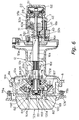
- Fig. 6 is a view corresponding to Fig. 3 in another embodiment;
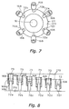
- Fig. 7 is a view corresponding to Fig. 4 in this other embodiment;
- Fig. 8 is a view corresponding to Fig. 5 in this other embodiment; and
- Fig. 9 is a diagram corresponding to Fig. 3 in yet another embodiment.
-
- Fig. 1 is a plan view of a dual-bearing reel to which an embodiment according to the present invention is applied.
- The dual-bearing reel shown in the figure is a bait reel chiefly used for lure fishing and includes a reel body 1, a
handle 2, and a star drag 3 for adjusting drag. Thehandle 2 is provided for rotating the spool and is disposed at one side of the reel body 1. The star drag 3 is disposed on the reel-body side of thehandle 2. Thehandle 2 is of a double-grip type having a plate-type arm portion 2a and holdingportions 2b, each of which is rotatably provided on respective ends of thearm portion 2a. The outer surface of thearm portion 2a of thehandle 2 is a smooth seamless surface to keep fishing line from getting tangled on it. - As shown in Fig. 2, the reel body 1 includes a
frame 5, a first side-cover 6, a second side-cover 7, and afront cover 10. The first side-cover 6 and the second side-cover 7 are disposed on respective sides of thereel frame 5. Thefront cover 10 is disposed to be open/closable on a front portion of theframe 5. Theframe 5 includes a pair ofside plates side plates - The second side-
cover 7, which is located on thehandle 2 side, is fixed to theside plate 9 by screws so that it may be detached from theside plate 9. The first side-cover 6, which is located on the opposite side of thehandle 2, is detachably attached to theside plate 8 of theframe 5. The first side-cover 6 includes acover body 6a and abrake case 64. Thecover body 6a curves outwardly in a bowl shape, and thebrake case 64 is fixed to thecover body 6a by screws. Thebrake case 64 will be described in detail later. - As shown in Fig. 2, the
spool 12, alevel wind mechanism 15, and athumb rest 17 are disposed inside theframe 5. Thelevel wind mechanism 15 is provided for uniformly reeling in fishing line around thespool 12. Thethumb rest 17 is a pad for the thumb during a thumbing operation. Agear mechanism 18, aclutch mechanism 13, a clutch engage/release mechanism 19, adrag mechanism 21, and acasting control mechanism 22 are disposed in the space between theframe 5 and the second side-cover 7. Thegear mechanism 18 transmits rotational force from thehandle 2 to thespool 12 and thelevel wind mechanism 15. The clutch engage/release mechanism 19 switches theclutch mechanism 13 in accordance with the operation of thethumb rest 17. Furthermore, acentrifugal braking mechanism 23 for preventing backlash during casting is provided between theframe 5 and the first side-cover 6. - The
spool 12 on either side has dish-shapedflange portions 12a, and between theflange portions 12a has tubular line-windingtrunk 12b. Also, thespool 12 has atubular boss portion 12c that is formed integral with the inner peripheral side of the line-windingtrunk 12b in the middle. By for example, a serration engagement thespool 12 is non-rotatably fixed to thespool spindle 16, which penetrates through theboss portion 12c. The means for fixing thespool 12 to thespool spindle 16 is not limited to the serration engagement and various other means such as key coupling or spline coupling may be used. - As shown in Fig. 3, the
spool spindle 16 penetrates theside plate 9 and extends outside the second side-cover 7. The extended end of thespool spindle 16 is rotatably supported by bearing 35b of aboss portion 29 which is provided with the second side-cover 7. Also, bearing 35a in thecentrifugal braking mechanism 23 rotatably supports the other end of thespool spindle 16. Thebearings spool spindle 16 has a central large-diameter portion 16a to which thespool 12 is fixed and two (right and left) small-diameter portions large diameter portion 16a. - The large-
diameter portion 16a is disposed in a space within thespool body 12b of thespool 12, andserrations 16d are formed on the outer surface of the middle of the large-diameter portion 16a, for fixing thespool 12. A pair ofbeveled portion 16e parallel to each other, and which form a part of theclutch mechanism 13, is provided on the right-hand side of the large-diameter portion 16a as shown in Fig. 3. - A rotary member 66 of the
centrifugal braking mechanism 23 is rotatably coupled to the periphery of the left small-diameter portion 16c to be axially movable. Thebearing 35a supports the rotary member 66 in thebrake case 64. Acoupling pin 24 for coupling the rotary member 66 is fitted on the right end of the small-diameter portion 16c as shown in Fig. 3. Thecoupling pin 24 diametrically penetrates the right end of the small-diameter portion 16c and couples the rotary member 66 to thespool spindle 16 to be non-rotatable yet axially shiftable. As a result, thebearing 35a via the rotary member 66 rotatably supports the other end of thespool spindle 16. - A
pinion gear 32 is supported on the right small-diameter portion 16b to be axially shiftable. Thebearing 35b rotatably supports the end of the small-diameter portion 16b on theboss portion 29. Also, both ends of thespool spindle 16 are made superficially spherical to keep down increase in rotational resistance. - The
level wind mechanism 15 includes aguide tube 25, aworm shaft 26, and aline guide 27. Theguide tube 25 is fixed between the pair ofside plates worm shaft 26 is rotatably supported in theguide tube 25. Agear 28a, which forms a part of thegear mechanism 18, is fixed to one end of theworm shaft 26. Also, aspiral groove 26a is formed on theworm shaft 26, and theline guide 27 is meshed with thespiral groove 26a. Theline guide 27 therefore reciprocates along theguide tube 25 by theworm shaft 26 being rotated via thegear mechanism 18. A fishing line is inserted in theline guide 27 and uniformly wound onto thespool 12. - The
gear mechanism 18 includes amain gear 31, apinion gear 32, the above-mentionedgear 28a, and agear 28b. Themain gear 31 is fixed to ahandle shaft 30. Thepinion gear 32 is cylindrical and is engaged with themain gear 31. Thegear 28a is fixed to one end of theworm shaft 26. Thegear 28b is non-rotatably fixed to thehandle shaft 30 and engaged with thegear 28a. - Disposed outward of the
side plate 9, thepinion gear 32 is a cylindrical member whose center thespool spindle 16 penetrates, as shown in Fig. 3. Thepinion gear 32 is coupled to thespool spindle 16 to be axially shiftable. Thepinion gear 32 includesteeth 32a, a meshingportion 32b, and aconstriction 32c as shown in Fig. 3. Theteeth 32a are formed circumferentially on the right end of thepinion gear 32 and mesh with themain gear 31. The meshingportion 32b is formed on the other side of thepinion gear 32. Theconstriction 32c is provided between theteeth 32a and the meshingportion 32b. The meshingportion 32b includes an oblong cavity formed in the end face of thepinion gear 32. Abeveled portion 16e formed on one end of the large-diameter portion 16a of thespool spindle 16 engages in the oblong cavity. In this embodiment, when thepinion gear 32 is moved outward, disengagingbeveled portion 16e of thespool spindle 16 from the oblong cavity in the meshingportion 32b, the rotational force from thehandle shaft 30 is not transmitted to thespool 12. Thus theclutch mechanism 13 is constituted by the oblong cavity in the meshingportion 32b and thebeveled portion 16e. - As shown in Fig. 2, the
thumb rest 17 is disposed in the rear of thespool 12 between the pair ofside plates thumb rest 17 is also used as a clutch lever. An elongated hole (not shown) is formed in theside plates frame 5, and thethumb rest 17 is supported to be shiftable in the elongated hole. Thus, thethumb rest 17 slides up and down along the elongated hole. - The clutch engage/
release mechanism 19 includes aclutch yoke 40 as shown in Fig. 3. By turning movement of thethumb rest 17, the clutch engage/release mechanism 19 shifts theclutch yoke 40 parallel to the axis of thespool spindle 16. Further, when thehandle shaft 30 is rotated in the line reeling-in direction, the clutch engage/release mechanism 19 shifts theclutch yoke 40 whereby theclutch mechanism 13 is automatically put on. Theclutch yoke 40 is disposed about the outer periphery of thespool spindle 16 and is supported on two pins 41 (only one of them is shown in the figure) to be shiftable parallel to the axis of thespool spindle 16. Thespool spindle 16 is rotatable relative to theclutch yoke 40. That is, this makes it so that theclutch yoke 40 does not rotate though thespool spindle 16 rotates. Also, in the middle of theclutch yoke 40 is anengaging portion 40a that is engaged in theconstriction 32c of thepinion gear 32. Moreover, aspring 42 is provided surrounding each of thepins 41 between theclutch yoke 40 and the second side-cover 7. Theclutch yoke 40 is always urged inward (i.e., clutch engagement-ward) by thespring 42. - In this configuration, the
pinion gear 32 is normally situated in the inward clutch-engaging position wherein the meshingportion 32b is engaged with thebeveled portion 16e of thespool spindle 16, which is the clutch-on state. On the other hand, when theclutch yoke 40 shifts thepinion gear 32 outward, the meshingportion 32b is disengaged from thebeveled portion 16e, which is the clutch-off state. - The
drag mechanism 21 includes as shown in Fig. 2 afriction washer 45 that presses on themain gear 31, and apressing plate 46 for pressing, thefriction washer 45 on themain gear 31 at a predetermined force by rotation of the star drag 3. - The
casting control mechanism 22 includes as shown in Fig. 3 a plurality offriction plates 51 arranged sandwiching either end of thespool spindle 16, and acap 52 for adjusting the grasping force on thespool spindle 16 due to thefriction plates 51. The left-end friction plates 51 are fitted within thebrake case 64. Thecap 52 is screw-mated with the circumferential surface of theboss portion 29. In thiscasting control mechanism 22, turning thecap 52 for example clockwise advances thecap 52 leftward in Fig. 3. This pressesspool spindle 16 further against thefriction plates 51 on thecap 52 end, and shifts slightly leftward in Fig. 3, which strengthens thefriction plate 51 pair's grasping force on thespool 12 and makes the braking force on thespool 12 larger. Turning thecap 52 counterclockwise retracts thecap 52 rightward in Fig. 3, and thespool spindle 16 shifts slightly rightward in Fig. 3 due to elasticity of thefriction plates 51 on thebrake case 64 end. This weakens thefriction plate 51 pair's grasping force, which lessens the braking force applied on thespool 12. - As shown in Fig. 2, the
centrifugal braking mechanism 23 is accommodated in thebrake case 64, configured in the first side-cover 6. Thebrake case 64 is a short cylindrical member having a bottom configured in the reel body 1. Thebrake case 64 may be fixed to thecover body 6a by using, for instance, twoscrews brake case 64 is attachably/detachably fitted into theside plate 8 by abayonet structure 14 at the circumference of acircular opening 8a formed in theside plate 8 for passing thespool 12. Thus, the first side-cover 6 is removably attached to theside plate 8. A cylindrically shaped bearinghousing 64a protruding inward is formed in the center of the bottom of thebrake case 64. Thebearing 35a for rotatably supporting thespool spindle 16, and the rotary member 66 of thecentrifugal braking mechanism 23 are accommodated in the bearinghousing 64a. Thefriction plates 51 of thecasting control mechanism 22 are fitted in a bottom surface formed intermediate axially in the bearinghousing 64a. - The
centrifugal braking mechanism 23 includes: the rotary member 66, supported in the bearinghousing 64a to be rotatable yet axially immobile; a plurality ofbraking members 68 fitted on the rotary member 66; astationary member 67 able to come into contact with thebraking members 68 in different frictional states; thecoupling pin 24; and a brakingforce adjusting mechanism 69 for adjusting braking force that develops from thebraking members 68 contacting thestationary member 67. - The rotary member 66 is supported via the
bearing 35a in the bearinghousing 64a to be allowed to rotate yet be axially immobile. The rotary member 66 includes arotor 71 coupled to thespool spindle 16 by thecoupling pin 24 to be non-rotatable yet permit axial shift, and six, for example, guideshafts 72 in a radiating arrangement on therotor 71. Therotor 71 includes a cylindrical portion 71a allowed to rotate fitted circumferentially on thesmall diameter portion 16c of thespool spindle 16 yet axially immobile, and aguide anchor 71b fitted to the Fig. 3 right-end outer periphery of the cylindrical portion 71a to be both non-rotatable and axially immobile. Thebearing 35a is fitted on the Fig. 3 left end of the cylindrical portion 71a. A large diameter portion is formed in the middle of the cylindrical portion 71a, sandwiched between the inner race of thebearing 35a and theguide anchor 71b. A pair of engaginggrooves 71c into which thecoupling pin 24 interlocks is formed on the right end of the cylindrical portion 71a. The axial length of the engaginggroove 71c is longer than the diameter of thecoupling pin 24 and an axial gap is formed between the bottom of the engaginggroove 71c and thecoupling pin 24. The rotary member 66 therefore allows axial shift in thespool spindle 16. The rotary member 66 thus is coupled by thecoupling pin 24 to be non-rotatable with respect to thespool spindle 16 yet to permit axial shift, and moreover is allowed to rotate supported in the bearinghousing 64a yet is axial immobile. The rotary member 66 therefore rotates linked with thespool 12. Nevertheless, even with thespool spindle 16 shifting axially, the rotary member 66 does not shift. - The
guide anchor 71b includes adisk portion 71d and ashaft anchor 71e. The inner side of thedisc plate portion 71d is non-rotatably fitted to the cylindrical portion 71a and is axially immobile. From the circumferential end of thedisc plate portion 71d heading peripherally outward of the bearinghousing 64a extends theshaft anchor 71e, inside which theguide shafts 72 are radially stood on their extended tips. Theshaft anchor 71e is a thick, disk-shaped member and, as shown in Fig. 4, sixregulator spaces 90a through 90f differing in length in the radial direction of theshaft anchor 71e are formed encompassing the stood sections of theguide shafts 72. Theguide shafts 72 are radially arranged in the centers of theregulator spaces 90a to 90f.Openings 91 in which thebraking members 68 are shiftable are formed at the outer peripheral ends of theregulator spaces 90a to 90f. - Each of the plurality of the
braking members 68 is a cylindrical member having base-end collar 68a. Thebraking members 68 are fitted on theguide shafts 72 to permit radial travel and shift radially outward under centrifugal force. Thecollars 68a are furnished to interlock with the openingportions 91, as shown in Fig. 5, when centrifugal force shifts thebraking members 68 radially, to check any further radially outward shift. Thebraking members 68 thus can travel radially outward different distances. Contact faces 68b that contact on abrake liner 70 fitted to thestationary member 67 are formed on the tips of thebraking members 68. The contact faces 68b are slant surfaces conforming to thebrake liner 70. - As shown in Fig. 5, the diametrical length of the
regulator space 90a to theopening 91 is set to a length at which the end of the brakingmember 68 shifted peripherally outward, when thestationary member 67 is in its retracted position parted furthest from the rotary member 66, cannot contact on thebrake liner 70. Further, the length of theregulator space 90f is set to a length at which the end of the brakingmember 68 shifted peripherally outward, when thestationary member 67 is in its advanced position, can contact on thebrake liner 70. The lengths of themiddle regulator spaces 90b to 90e are then set to become shorter in even intervals, for example, in between. - The
stationary member 67 is a cylindrical component having acylindrical portion 67a disposed peripherally outward of the rotary member 66; and asupport portion 67b formed integrally with thecylindrical portion 67a on its inner periphery and supported by the bearinghousing 64a to permit axial travel. Thebrake liner 70 is removably fitted to the inner peripheral surface of thecylindrical portion 67a, and has a tapered surface flaring forward towards thespool 12. On the leading edge of the outer peripheral surface of thecylindrical portion 67a, aninterlock projection 67c protrudes diametrically. Theinterlock projection 67c is interlocked with anengagement groove 64b formed on the inner peripheral surface of thebrake case 64 along the axial direction. Consequently, thestationary member 67 is made non-rotatable with respect to thebrake case 64, i.e. to the reel body 1. Thesupport portion 67b is fitted to the bearinghousing 64a to permit axial travel. A cam projection 92, which the brakingforce adjusting mechanism 69 comprises, is formed on the outward lateral surface of thesupport portion 67b. The cam projection 92 is an arc shaped protrusion, and the amount by which it projects gradually enlarges going one way circumferentially. - The braking
force adjusting mechanism 67 is a device for moving thestationary member 67 fore-and-aft (in the spool axial direction) and includes aknob 80 and a convertingmechanism 81. Theknob 80 is supported in thebrake case 64 to permit rotation. The convertingmechanism 81 converts rotation of theknob 80 into a fore-and-aft advancing movement of thestationary member 67. Theknob 80 is partially exposed outside the first side-cover 6 and is manipulable externally of the reel body 1. Theknob 80 may be positioned into, for instance, seven-stage rotatory positions by means of a (not shown) positioning mechanism. That is, there are one brake-releasing position and six braking positions. An arc-shapedcam projection 93, which the convertingmechanism 81 comprises, is formed on the right-end face of theknob 80, in a position opposing the cam projection 92. The amount by which thecam projection 93 protrudes gradually enlarges going the other way circumferentially, being an oppositely protruding form to that of the cam projection 92. The leading edge of the cam projection 92 on thestationary member 67 abuts on thecam projection 93. The convertingmechanism 81 is composed of the twocam projections 92 and 93 and areturn spring 94. Thereturn spring 94 is arranged between thesupport portion 67b and acollar 64c fixed to the outer peripheral surface of the bearinghousing 64a to be axially immobile, compressed on the outer peripheral surface of the bearinghousing 64a, wherein it urges thestationary member 67 Fig. 3 leftward (toward its retracted position). - In the braking
force adjusting mechanism 69, when theknob 80 is rotated in the one direction, the cam projection 92 rides up on thecam projection 93 and thestationary member 67 advances Fig. 3 rightward. Conversely, when theknob 80 is rotated in the other direction, thestationary member 67 retracts urged by thereturn spring 94. Herein, since thebrake liner 70 is configured with the forward flaring tapered surface thestationary member 67 shifting axially changes the diameter of the osculating circle for thebrake liner 70 with the brakingmember 68. Accordingly, varying the travel distance until thebraking members 68 contact thebrake liner 70, and varying the number ofbraking members 68 that can come into contact with thebrake liner 70 makes it simple to adjust the braking force from outside the reel body 1. - Herein for example when the
knob 80 is put into the brake-release position, disposing thestationary member 67 into the retracted position, all of thebraking members 68 are out of contact with thebrake liner 70, and braking force does not act on thespool 12. This state is shown on the lower side of the centerline X in Fig. 3, and is indicated as well by the solid line in Fig. 5. Then when theknob 80 is rotated to advance thestationary member 67 gradually, drawing it near the rotary member 66, thebraking members 68 contact thebrake liner 70; moreover the number ofbraking members 68 coming into contact increases corresponding to the amount by which thestationary member 67 advances. Consequently, the braking force of thecentrifugal braking mechanism 23 gradually increases. Thus, as indicated on the upper side of the centerline X in Fig. 3 and by the dashed line in Fig. 5, when the advanced position is reached, all of thebraking members 68 are put into contact with thebrake liner 70 and the braking force becomes maximal. - Since the centrifugal force increases in proportion to the square of the rotational speed, in the
centrifugal braking mechanism 23 the braking force at each position on thestationary member 67 increases in proportion to the square of the rotational speed. - The
centrifugal braking mechanism 23 braking force obtained by adjusting theknob 80 is not liable to fluctuate even if the braking force due to thecasting control mechanism 22 alters. This is because the rotary member 66 is not directly fixed non-rotatably to thespool spindle 16, but is non-rotatably coupled to it and permits axial travel via thecoupling pin 24--and at the same time is supported on the reel body 1 to permit rotation yet be axially immobile. That is, when thespool spindle 16 shifts axially by adjustment of thecasting control mechanism 22, although thecoupling pin 24 shifts axially, the rotary member 66 does not shift. Consequently, the clearance between thestationary member 67 adjusted by theknob 80 and the rotary member 66 does not fluctuate though thespool spindle 16 shifts. Therefore, thecentrifugal braking mechanism 23 braking force is not liable to fluctuate even if the braking force due to thecasting control mechanism 22 alters. - In a normal state, the
clutch yoke 40 is pressed inwardly (towards the left-hand side in Fig. 3) by thespring 42 and, hence, thepinion gear 32 is moved to the engaging position. In this state, the meshingportion 32b of thepinion gear 32 is engaged with thebeveled portion 16e of thespool spindle 16 to achieve a clutch-on state. As a result, the rotational force from thehandle 2 is transmitted to thespool 12 via thehandle shaft 30, themain gear 31, thepinion gear 32 and thespool spindle 16 to rotate thespool 12 in the line reeling-in direction. At this time, although a centrifugal force is applied to thebraking members 68 of thecentrifugal braking mechanism 23 to move thebraking members 68 outwardly in the radius direction, the braking force does not become so large since the rotation speed of thespool 12 is low and, hence, it does not interfere with the rotation of thehandle 2. However, if it is necessary to reduce the braking force, thestationary member 67 may be positioned at a receded position by using theknob 80. As a result, all thebraking members 68 cannot make contact with thebrake liner 70 and no braking force by thecentrifugal braking mechanism 23 is applied to thespool 12. - When a fishing line is cast, the braking force is adjusted to prevent backlash by using the
knob 80. When thestationary member 67 is gradually moved forward by rotating theknob 80, thebraking members 68 starts to make contact with thebrake liner 70 and the number of the braking members 53 which make contact with thebrake liner 70 is increased in accordance with the degree of movement of thestationary member 67. As a result, the braking force exerted by thecentrifugal braking mechanism 23 is gradually increased. When thestationary member 67 reaches the most advanced position, all thebraking members 68 make contact with thebrake liner 70 and the braking force reaches its maximum. - Then, the
thumb rest 17 may be pushed downwardly. In this embodiment, thethumb rest 17 is moved along an elongated hole formed on theside plates clutch yoke 40 is moved outwardly according to the movement of thethumb rest 17, and thepinion gear 32 which is engaged with theclutch yoke 40 is also moved in the same direction. As a result, the engaging portion of thepinion gear 32 is disengaged from thebeveled portion 16e of thespool spindle 16 and the clutch is entered to a clutch-off state. In the clutch-off state, the rotation from thehandle shaft 30 is not transmitted to neither thespool 12 nor thespool spindle 16, and thespool 12 may freely rotate. When a fishing rod is swung in the clutch-off state so that a reel is inclined in the axis direction in order for thespool spindle 16 to face a vertical surface while thumbing thespool 12 using a thumb on thethumb rest 17, a lure is cast and thespool 12 rotates vigorously in the line-releasing direction. - In this state, the
spool spindle 16 is rotated in the line-releasing direction by the rotation of thespool 12 and the rotation is transmitted to the rotary member 66. When the rotary member 66 is rotated, thebraking members 68 make contact with thebrake liner 70 and thespool 12 is braked by thecentrifugal braking mechanism 23 to prevent a generation of backlash. - In addition, if backlash of the
spool 12 is caused by any chance, the problem may be easily dissolved since the first side-cover 6 is easily removed due to thebayonet structure 14. -
- (a) Although in the foregoing embodiment the
guide shafts 72 are disposed radiating along diametric directions, as shown in Fig. 6,guide shafts 72a to 72f may be disposed radiating orthogonally to thebrake liner 170. Also, control of the travel distance may be by the guide shafts. As shown in Fig. 6, thecentrifugal braking mechanism 123 is placed in thebrake case 164. A bearinghousing 64a of a cylindrical shape protruding outwardly as well as inwardly is formed on the center of the bottom of thebrake case 164. Thebearing 135a for supporting thespool spindle 16 is accommodated in the bearinghousing 64a and thefrictional plate 151 of thecasting control mechanism 22 is attached to the bottom surface thereof. Also, arotation supporting member 65 is fixed to the end of the bearinghousing 64a by a screw. Therotation supporting member 65 is a cylindrical member having a narrow part, and acollar 65a for being engaged with one end of thereturn spring 83 which forms a part of the brakingforce adjusting mechanism 169 is formed on the outer surface thereof. Therotary member 166 of thecentrifugal braking mechanism 123 is rotatably supported by the outer periphery of an end (right-hand side in Fig. 3) of therotation supporting member 65 in a non-movable manner in the axial direction via a pair ofbearings 65b. As a result, therotary member 166 is rotatably supported by the reel body 1 in a non-movable manner in the axial direction.Thecentrifugal braking force 123 includes therotary member 166, the stationary member 167, thebraking members 168, and the brakingforce adjusting mechanism 169. Therotary member 166 is rotatably supported by therotation supporting member 65 in a non-movable manner in the axial direction. The stationary member 167 is placed in thebrake case 164 in a movable manner in the back and forth direction. Thebrake liner 170 of a cone shape is disposed in the inner side of the stationary member 167. The number of thebraking members 168 may be six, and they may be radially disposed inner side of thebrake liner 170 with a space between each other in the circumferential direction. The brakingforce adjusting mechanism 169 is used to move the stationary member 167 in the spool axis direction.Therotary member 166 includes therotor 171, and theguide shafts 72a to 72f. Therotor 171 is non-rotatably coupled to thespool spindle 16 in a movable manner in the axial direction by acoupling pin 124. The number of theguide shafts 72a to 72f may be six, and they are disposed radially to therotor 171 so as to substantially cross thebrake liner 170 orthogonally.Therotor 171 is a member having a deformed cylindrical shape and acone surface 171f having the same center as thebrake liner 170 is formed on the left outer surface of the rotating portion with a predetermined space from thebrake liner 170. Also, an engaging groove 171c to be engaged with thecoupling pin 124 is formed on the right end of therotor 171. As shown in Figs. 7 and 8, theguide shafts 72a to 72f are radially provided with thecone surface 171f. Therotary member 166 is non-rotatably coupled to thespool spindle 16 in a movable manner in the axial direction by thecoupling pin 124 and is rotatably supported by therotation supporting member 65 in a non-movable manner in the axial direction. For this reason, therotary member 166 rotates together with thespool 12. However, therotary member 166 does not move in the axial direction if thespool spindle 16 is moved in the axial direction.As shown in Figs. 7 and 8, the length of each of the sixguide shafts 72a to 72f differs from each other and, for instance, the length may be reduced from theguide shaft 72a in alphabetical order with theguide shaft 72f be the shortest. The base portion of each of theguide shafts 72a to 72f is fixed to thecone surface 171f. Astopper portion 73 having a large diameter for restricting the movement of therespective braking member 168 in the outward direction to the respective limit position is formed at the end portion of each of theguide shafts 72a to 72f. Herein, the length of theguide shaft 72a, as shown in Fig. 8, is set to a length at which ends of thebraking members 168 shifted peripherally outward, when the stationary member 167 is in its retracted position parted furthest from therotary member 166, cannot contact on thebrake liner 170. At the same time, when the stationary member 167 is in its advanced position, drawn closest to therotary member 166, its leading edge does not touch thebrake liner 170. Also, the length of theguide shaft 72f is predetermined so that the end of thebraking member 168 which moved outwardly may make contact with thebrake liner 170 when the stationary member 167 is located at the most advanced position. The length of each of theguide shafts 72b to 72e may be predetermined so that it differs from each other with an equal interval between theguide shafts 72b and 72e.Each of thebraking members 168 is acylindrical member 168 and may make contact with thebrake liner 170 by the centrifugal force. Each of thebraking member 168 is movably coupled to therespective guide shafts 72a to 72f in a movable manner in the axial direction. Asmall diameter portion 168c which is supported by therespective guide shafts 72a to 72f and alarge diameter portion 168d supported by thestopper portion 73 are formed on the inner surface of therespective braking member 168. The inner diameter of thesmall diameter portion 168c is larger than theguide shafts 72a to 72f and smaller than thestopper portion 73. The inner diameter of thelarge diameter portion 168d is larger than thestopper portion 73. For this reason, the movement of each of thebraking members 168 in the outward direction is restricted to a limit position different from each other.As shown in Fig. 6, the stationary member 167 is non-rotatably coupled to the outer periphery of the bearinghousing 164a of thebrake case 164 in a movable manner in the back and forth direction of the axial direction of therotary member 166. In Fig. 6, it is shown that the upper portion is placed at a receded position and the lower portion is placed at an advanced position. The stationary member 167 includes acylindrical portion 167a having a cone shape and the supportingportion 167b which is supported by the bearinghousing 164a. Thecylindrical portion 167a faces the outer periphery side of therotary member 166 so as to be concentric with therotary member 166. Thebrake liner 170 is fixed to the inner side of thecylindrical portion 167a. The supportingportion 167b is a ring-shape member having, for instance, serration teeth on the inner periphery thereof to be engaged with serration teeth formed on the outer periphery surface of the bearinghousing 164a. Thecam projection 192 of an arc shape is formed on the outer side surface of the supportingportion 167b. In this configuration, the stationary member 167 may be non-rotatably supported by thebrake case 164 in a movable manner in the back and forth direction.The brakingforce adjusting mechanism 169 is a mechanism for moving the stationary member 167 in the back and forth direction (i.e., the spool axis direction) and includes theknob 180 and the convertingmechanism 181. Theknob 180 is rotatably supported by the bearinghousing 164a. The convertingmechanism 181 converts the rotation of theknob 180 to the back and forth movement of the stationary member 167. Theknob 180 is exposed outside of theside cover 106 and may be operated from outside of the reel body 1. Acam groove 82 which forms a part of the convertingmechanism 181 is formed at the right end surface of theknob 180. Thecam groove 82 has an arc shape and its depth differs depending on the rotational angle. For instance, the depth becomes gradually shallow when theknob 180 is rotated in one direction. The end of thecam projection 192 of the stationary member 167 makes contact with thecam groove 82. The convertingmechanism 181 includes thecam groove 82, thecam projection 192, and thereturn spring 83. Thereturn spring 83 is disposed at the outer periphery of the bearinghousing 164a between thecollar 65a and the stationary member 167 in a compressed state. Thereturn spring 83 urges the stationary member 167 towards the left-hand side of Fig. 3 (i.e., towards a receded position).In the brakingforce adjusting mechanism 169, when theknob 180 is rotated in one direction, thecam projection 192 runs on thecam groove 82 and the stationary member 167 is moved forwardly in the right-hand direction in Fig. 3. On the other hand, when theknob 180 is rotated in the opposite direction, the stationary member 167 moves backward due to the urging force of thereturn spring 83. In this embodiment, since thebrake liner 170 has the cone shape surface, the diameter of a circle formed by the contact of thebraking members 168 with thebrake liner 170 varies in accordance with the movement of the fixingmember 7 in the axial direction. Accordingly, the distance required for each of thebraking members 168 to move in order to make contact with thebrake liner 170 changes and, hence, the number of thebraking members 168 which are capable of making contact with thebrake liner 170 varies. Thus, the braking force may be easily adjusted by an operation from outside of the reel body 1.In this embodiment, if the stationary member 167 is placed at the most receded position using, for instance, the brakingforce adjusting mechanism 169, no brakingmembers 168 may make contact with thebrake liner 170 and, hence, no braking force is applied to thespool 12. When theknob 180 is rotated so that the stationary member 167 gradually moves towards therotary member 166, thebraking members 168 start to make contact with thebrake liner 170 and the number of thebraking members 168 that make contact with thebrake liner 170 increases depending on the degree of movement of the stationary member 167. As a result, the braking force of thecentrifugal braking mechanism 123 gradually increases. Finally, when the stationary member 167 reaches the most advanced position, all of thebraking members 168 may make contact with thebrake liner 170 and the braking force reaches its maximum. - (b) Although the braking force is changed in proportion
to the degree of movement of the
knob braking members braking members knob - (c) Although the coupling pins 24 or 124 are used as a
coupling means in the above embodiments, any coupling means
is acceptable as long as it non-rotatably couples the
rotary member 66 or 166 to thespool spindle 16, which is an interlocking member, in a movable manner in the axial direction. - (d) Although the
braking members respective guide shaft members 86 may be pivotably coupled to the rotary member 266. In such a configuration, the rotary member 266 includes therotor 271 androckers 87 for movably coupling therespective braking member 86 to therotor 271. Thus, thebraking members 86 are movably coupled to the rotary member 266. Each of therockers 87 is disposed in the circumferential direction of therotor 271 with a space between each other and movably couples thebraking members 86 around an axis along the chord direction. Each of thebraking members 86 has a lever shape and itsend portion 86 is curved outwardly towards the spool axis direction. The position G of the center of gravity of thebraking members 86 is placed at thespool 12 side with respect to the center of movement S. Thestationary member 267 may make contact with theend portion 86a of thebraking members 86 and has an annularly shapedbrake liner 270 orthogonal to the rotational axis of the rotary member 266. The configuration in which the rotary member 266 is rotatably supported by therotation supporting member 65 in a non-movable manner in the axial direction and the rotary member 266 is non-rotatably coupled to thespool spindle 16 in a movable manner in the axial direction is the same as the above embodiment. In thecentrifugal braking mechanism 123 having the above-mentioned configuration, when thespool 12 is rotated and a centrifugal force is applied to thebraking members 86, theend portion 86a of thebraking members 86 moves towards thebrake liner 270 and makes contact with thebrake liner 270 to brake thespool 12. The braking force applied at that time depends on moment, which is determined by the shortest distance between the center of gravity G and the center of movement S of thebraking members 86 and the centrifugal force acting on the center of gravity G, and the shortest distance between the center of movement S and the contacting position of thebraking members 86 with thebrake liner 270. For this reason, the braking force obtained is weaker than that obtained in the above embodiment. Also, the adjustment of the braking force is carried out by moving thestationary member 267 in the axial direction so that the center of gravity G is moved with respect to the center of movement S. Thus, although the braking force may be changed continuously, the degree of change is relatively small.In this embodiment, effect similar to the above-mentioned embodiment may be obtained since the distance between the rotary member 266 and thestationary member 267 is not changed when thespool spindle 16 is moved in the axial direction. - (e) Although the rotary member 266 is coupled to the
spool spindle 16 via thecoupling pin 124 in the foregoing embodiment, the rotary member 266 may be directly coupled to thespool 12 via a coupling means. - (f) Although the coupling means is always maintained in a coupling state in the above embodiment, it is possible to adapt a structure in which the state of a coupling means may be switched from a coupling state to a non-coupling state or vice versa. In such a case, regardless of the setting of the braking state of the centrifugal braking mechanism, the braking force may be instantly released by simply switching to the non-coupling state. Similarly, the braking force may be restored to its original strength by switching to the coupling state.
-
- According to the present invention, the friction state between the braking members and the fixing members is changed by the position of the fixing member in the axial direction and the braking force may be changed accordingly. Thus, the braking force may be adjusted by a simple operation in which the fixing member is moved in the axial direction of the rotating member by using the braking force adjusting means. Also, the rotating member is rotatably disposed in the reel body in a non-movable manner in the axial direction and is coupled to an interlocking member by a coupling means in a movable manner in the axial direction. Thus, if the interlocking member such as the spool shaft is moved in the axial direction, the rotating member does not move in the axial direction and the distance between the rotating member and the fixing member does not change unless the fixing member is forced to move. For this reason, the predetermined braking force is not changed even if the interlocking member is moved and, therefore, the adjustment of the braking force may be performed accurately.
- While only selected embodiments have been chosen to illustrate the present invention, to those skilled in the art it will be apparent from this disclosure that various changes and modifications can be made herein without departing from the scope of the invention as defined in the appended claims. Furthermore, the foregoing description of the embodiments according to the present invention is provided for illustration only, and not for the purpose of limiting the invention as defined by the appended claims.
Claims (8)
- A braking device for braking a spool (12) fitted in a reel body (1) of a dual-bearing reel, said braking device comprising:a rotary member (66) rotatably supported in the reel body (1) to permit rotation yet be axially immobile;a plurality of braking members (68) for travel under centrifugal force, fitted on said rotary member (66) to permit travel;a stationary member (67) non-rotatably fitted on said reel body (1) yet permitting shift axially of said rotary member (66), said stationary member (67) being adapted to travel axially to contact, in differing frictional states, said braking members (68) shifted under centrifugal force;coupling means (24) for coupling said rotary member (66) non-rotatably, yet permitting axial travel, to a linking member for linking with the spool (12); andbraking force adjusting means (69) for shifting said stationary member (67) in an axial direction to adjust braking force developing from contact between said braking members (68) and said stationary member (67).
- A braking device as claimed in Claim 1, said spool (12) being rotational on a spindle (16), wherein:said spool (12) is non-rotatably coupled to the spool spindle (16) as said linking member; andsaid coupling means (24) is provided on said spool spindle (16) and couples said rotary member (66) to said spool spindle (16) non-rotatably yet permitting axial travel.
- A braking device as claimed in Claim 1 or Claim 2 wherein:peripherally outward of said rotary member (66), said stationary member (67) has on an inner peripheral surface thereof a conically shaped, forward-flaring braking face (70) disposed concentric with said rotary member (66); andsaid braking members (68) are fitted to said rotary member (66) for contact with said braking face (70) under centrifugal force, said braking members (68) being arranged radially toward said braking face (70) and permitted travel as far as mutually differing travel-limited positions.
- A braking device as claimed in any preceding claim wherein said braking members (68) are fitted on said rotary member (66) to permit travel in a direction substantially orthogonal to said braking surface.
- A braking device as claimed in any preceding claim wherein said stationary member (67) comprises:a support portion (67b) supported on said reel body (1) to be non-rotatable yet permitted to travel axially of said spool (12), anda main body (67a) formed integrally with said support portion (67b), having a conically shaped inner peripheral surface wherein said braking face (70) is provided; and wherein said braking force adjusting means (69) comprises:a knob (80) movably fitted to and permitted movement on said reel body (1), and being exposed exteriorly of said reel body (1), anda converting mechanism (81) for converting movement of said knob (80) to movement of said main body (67a) axially of said spool (12).
- A braking device as claimed in Claim 1 or Claim 2:said braking members (68) being fitted to, and permitted to rock around axes along chord directions of, said rotary member (266), and being arranged radially and spaced apart circumferentially of said rotary member (266), wherein positions of their gravitational centres are disposed more toward said spool (12) than their rocking centres; andsaid stationary member (267) having an annular braking face (270) approximately orthogonal to the rotational axis of said rotary member (266), for endwise contact with said braking members (68).
- A braking device as claimed in any preceding claim, further comprising a casting control mechanism (22) for braking said spool (12) by grasping said linking member.
- A centrifugal braking mechanism (23) for spool cast braking in a dual-bearing reel having a casting control mechanism (22) for adjustable, direct spool-spindle braking, said centrifugal braking mechanism (23) comprising:a brake cylinder (67) non-rotatably supported yet permitted adjustable axial travel on a housing (64a) in which a spool-spindle bearing (35a) is fitted on a spool flange end of the dual-bearing reel, said brake cylinder (67) having a rim-ward brake lining (70);a centrifugal-braking rotary member (66) rotatively supported via the spool-spindle bearing (35a) yet axially immobilised in the spool-flange end of the dual-bearing reel, said rotary member (66) carrying braking elements (68) for contact circumferentially with the brake lining (70) to develop spool-braking force differential in correspondence with axial adjustment of said brake cylinder (67); anda rotary member cylindrical extension (67a) configured for rotational interlocking with a spool-spindle link (64b) yet permitting spool-spindle axial shift; whereinthe spool-spindle axial shift is such that spool-braking force in the centrifugal braking mechanism (23) is adjustably differential regardless of casting control mechanism adjustment.
Applications Claiming Priority (2)
| Application Number | Priority Date | Filing Date | Title |
|---|---|---|---|
| JP11133199A JP2000316438A (en) | 1999-05-13 | 1999-05-13 | Dual bearing reel braking system |
| JP13319999 | 1999-05-13 |
Publications (3)
| Publication Number | Publication Date |
|---|---|
| EP1051906A2 true EP1051906A2 (en) | 2000-11-15 |
| EP1051906A3 EP1051906A3 (en) | 2000-12-13 |
| EP1051906B1 EP1051906B1 (en) | 2004-07-28 |
Family
ID=15099053
Family Applications (1)
| Application Number | Title | Priority Date | Filing Date |
|---|---|---|---|
| EP00303963A Expired - Lifetime EP1051906B1 (en) | 1999-05-13 | 2000-05-11 | Dual-bearing reel braking device |
Country Status (7)
| Country | Link |
|---|---|
| US (1) | US6371396B1 (en) |
| EP (1) | EP1051906B1 (en) |
| JP (1) | JP2000316438A (en) |
| KR (1) | KR100646438B1 (en) |
| AT (1) | ATE271778T1 (en) |
| DE (1) | DE60012411T2 (en) |
| TW (1) | TW474784B (en) |
Cited By (4)
| Publication number | Priority date | Publication date | Assignee | Title |
|---|---|---|---|---|
| CN103380765A (en) * | 2012-05-04 | 2013-11-06 | Doyo工程有限公司 | Fishing reel having centrifugal brake system |
| CN104273106A (en) * | 2013-07-09 | 2015-01-14 | Doyo工程有限公司 | Fishing reel having precision centrifugal brake system |
| CN105309400A (en) * | 2014-07-16 | 2016-02-10 | 株式会社岛野 | Dual-bearing reel |
| US20230363368A1 (en) * | 2022-05-12 | 2023-11-16 | Accurate Grinding And Mfg. Corp. Dba Accurate Fishing Products | Cast control system for a fishing reel |
Families Citing this family (15)
| Publication number | Priority date | Publication date | Assignee | Title |
|---|---|---|---|---|
| KR100451886B1 (en) * | 2002-09-12 | 2004-10-08 | 주식회사 바낙스 | Apparatus for centrifugal brake of bait-cast reel |
| US6955315B2 (en) * | 2004-02-13 | 2005-10-18 | Doyo Engineering Co., Ltd. | Apparatus for preventing backlash of spool used in baitcasting reel |
| US6959886B1 (en) * | 2004-11-16 | 2005-11-01 | Yeon Seok Rho | Bait casting reel |
| US20060175449A1 (en) * | 2005-02-01 | 2006-08-10 | Doyo Engineering Co., Ltd. | Anti-backlash apparatus of bait reel |
| KR100702066B1 (en) * | 2005-04-28 | 2007-03-30 | 연 석 노 | Baitcast reel |
| KR200427970Y1 (en) * | 2006-06-23 | 2006-10-04 | 주식회사 도요엔지니어링 | Bait Reel Externally Adjusted Backlash Preventer |
| US20110079672A1 (en) * | 2009-10-07 | 2011-04-07 | Hyunkyu Kim | Automatic external adjustable spool braking system |
| KR200464020Y1 (en) | 2010-09-16 | 2012-12-06 | 주식회사 코커스 | Fishing reel of brush brake apparatus |
| JP5718119B2 (en) * | 2011-03-29 | 2015-05-13 | 株式会社シマノ | Centrifugal braking device for double-bearing reel |
| JP5926564B2 (en) * | 2012-01-18 | 2016-05-25 | 株式会社シマノ | Double-bearing reel spool braking device and double-bearing reel |
| US10385929B2 (en) | 2016-01-06 | 2019-08-20 | Boninfante Friction, Inc. | Vehicle input shafts |
| JP6846156B2 (en) * | 2016-10-19 | 2021-03-24 | 株式会社シマノ | Double bearing reel |
| US10602730B2 (en) * | 2017-06-23 | 2020-03-31 | Shimano Inc. | Dual-bearing reel |
| US10918096B2 (en) | 2017-07-11 | 2021-02-16 | W.C. Bradley/Zebco Holdings, Inc. | Centrifugal braking system for baitcast fishing reels |
| US11864543B2 (en) * | 2021-01-25 | 2024-01-09 | Cary Hogan JONES | Fly fishing reel with brake assembly and methods |
Citations (1)
| Publication number | Priority date | Publication date | Assignee | Title |
|---|---|---|---|---|
| JPH10304798A (en) | 1997-03-06 | 1998-11-17 | Ryobi Ltd | Centrifugal braking device for double bearing reel |
Family Cites Families (1)
| Publication number | Priority date | Publication date | Assignee | Title |
|---|---|---|---|---|
| JP3727149B2 (en) * | 1997-09-04 | 2005-12-14 | 株式会社シマノ | Centrifugal braking device for double-bearing reel |
-
1999
- 1999-05-13 JP JP11133199A patent/JP2000316438A/en active Pending
-
2000
- 2000-05-05 TW TW089108573A patent/TW474784B/en active
- 2000-05-09 KR KR1020000024622A patent/KR100646438B1/en not_active Expired - Fee Related
- 2000-05-11 AT AT00303963T patent/ATE271778T1/en not_active IP Right Cessation
- 2000-05-11 DE DE60012411T patent/DE60012411T2/en not_active Expired - Fee Related
- 2000-05-11 EP EP00303963A patent/EP1051906B1/en not_active Expired - Lifetime
- 2000-05-11 US US09/568,991 patent/US6371396B1/en not_active Expired - Lifetime
Patent Citations (1)
| Publication number | Priority date | Publication date | Assignee | Title |
|---|---|---|---|---|
| JPH10304798A (en) | 1997-03-06 | 1998-11-17 | Ryobi Ltd | Centrifugal braking device for double bearing reel |
Cited By (7)
| Publication number | Priority date | Publication date | Assignee | Title |
|---|---|---|---|---|
| CN103380765A (en) * | 2012-05-04 | 2013-11-06 | Doyo工程有限公司 | Fishing reel having centrifugal brake system |
| CN104273106A (en) * | 2013-07-09 | 2015-01-14 | Doyo工程有限公司 | Fishing reel having precision centrifugal brake system |
| JP2015015947A (en) * | 2013-07-09 | 2015-01-29 | 株式会社ドヨエンジニアリング | Fishing reel with precision centrifugal braking system |
| CN104273106B (en) * | 2013-07-09 | 2016-10-05 | Doyo工程有限公司 | Possesses the fishing lines reel of accurate centrifugal brake system |
| CN105309400A (en) * | 2014-07-16 | 2016-02-10 | 株式会社岛野 | Dual-bearing reel |
| US20230363368A1 (en) * | 2022-05-12 | 2023-11-16 | Accurate Grinding And Mfg. Corp. Dba Accurate Fishing Products | Cast control system for a fishing reel |
| US12201102B2 (en) * | 2022-05-12 | 2025-01-21 | Accurate Grinding and Mfg. Corp. | Cast control system for a fishing reel |
Also Published As
| Publication number | Publication date |
|---|---|
| KR100646438B1 (en) | 2006-11-14 |
| KR20010066787A (en) | 2001-07-11 |
| EP1051906B1 (en) | 2004-07-28 |
| DE60012411T2 (en) | 2005-07-28 |
| JP2000316438A (en) | 2000-11-21 |
| TW474784B (en) | 2002-02-01 |
| DE60012411D1 (en) | 2004-09-02 |
| US6371396B1 (en) | 2002-04-16 |
| EP1051906A3 (en) | 2000-12-13 |
| ATE271778T1 (en) | 2004-08-15 |
Similar Documents
| Publication | Publication Date | Title |
|---|---|---|
| EP1051906B1 (en) | Dual-bearing reel braking device | |
| EP1031279B1 (en) | Centrifugal braking device for double bearing reel | |
| JP6177550B2 (en) | Double-bearing reel spool braking device and double-bearing reel | |
| EP1072191B1 (en) | Dual-bearing reel centrifugal braking device | |
| US6196485B1 (en) | Dual-bearing reel centrifugal braking device | |
| JP2014176360A5 (en) | ||
| JP6284306B2 (en) | Spool braking device for double-bearing reel | |
| US5277379A (en) | Spinning reel for fishing | |
| JP2018038328A (en) | Double-bearing reel | |
| JP2017148027A (en) | Double bearing reel | |
| CN108967378B (en) | Reel for fishing | |
| JP2014217341A5 (en) | ||
| TWI624224B (en) | Double bearing reel reel brake device and double bearing reel | |
| US6293483B1 (en) | Braking device for dual-bearing reel | |
| JP6267874B2 (en) | Spool braking device for double-bearing reel | |
| JP3727149B2 (en) | Centrifugal braking device for double-bearing reel | |
| JP3747431B2 (en) | Centrifugal braking device for double-bearing reel | |
| JP2016220549A (en) | Double-bearing reel | |
| JP6876159B2 (en) | Double bearing reel | |
| JP3747430B2 (en) | Centrifugal braking device for double-bearing reel | |
| JP2019004865A (en) | Double bearing reel | |
| JP3009074B2 (en) | Double bearing reel | |
| JP3797832B2 (en) | Centrifugal braking device for double-bearing reel | |
| JPH0629033Y2 (en) | Double bearing reel | |
| JP6389689B2 (en) | Double bearing reel |
Legal Events
| Date | Code | Title | Description |
|---|---|---|---|
| PUAI | Public reference made under article 153(3) epc to a published international application that has entered the european phase |
Free format text: ORIGINAL CODE: 0009012 |
|
| PUAL | Search report despatched |
Free format text: ORIGINAL CODE: 0009013 |
|
| AK | Designated contracting states |
Kind code of ref document: A2 Designated state(s): AT BE CH CY DE DK ES FI FR GB GR IE IT LI LU MC NL PT SE |
|
| AX | Request for extension of the european patent |
Free format text: AL;LT;LV;MK;RO;SI |
|
| AK | Designated contracting states |
Kind code of ref document: A3 Designated state(s): AT BE CH CY DE DK ES FI FR GB GR IE IT LI LU MC NL PT SE |
|
| AX | Request for extension of the european patent |
Free format text: AL;LT;LV;MK;RO;SI |
|
| 17P | Request for examination filed |
Effective date: 20010601 |
|
| AKX | Designation fees paid |
Free format text: AT BE CH CY DE DK ES FI FR GB GR IE IT LI LU MC NL PT SE |
|
| 17Q | First examination report despatched |
Effective date: 20030520 |
|
| GRAP | Despatch of communication of intention to grant a patent |
Free format text: ORIGINAL CODE: EPIDOSNIGR1 |
|
| GRAS | Grant fee paid |
Free format text: ORIGINAL CODE: EPIDOSNIGR3 |
|
| GRAA | (expected) grant |
Free format text: ORIGINAL CODE: 0009210 |
|
| AK | Designated contracting states |
Kind code of ref document: B1 Designated state(s): AT BE CH CY DE DK ES FI FR GB GR IE IT LI LU MC NL PT SE |
|
| PG25 | Lapsed in a contracting state [announced via postgrant information from national office to epo] |
Ref country code: NL Free format text: LAPSE BECAUSE OF FAILURE TO SUBMIT A TRANSLATION OF THE DESCRIPTION OR TO PAY THE FEE WITHIN THE PRESCRIBED TIME-LIMIT Effective date: 20040728 Ref country code: LI Free format text: LAPSE BECAUSE OF FAILURE TO SUBMIT A TRANSLATION OF THE DESCRIPTION OR TO PAY THE FEE WITHIN THE PRESCRIBED TIME-LIMIT Effective date: 20040728 Ref country code: FI Free format text: LAPSE BECAUSE OF FAILURE TO SUBMIT A TRANSLATION OF THE DESCRIPTION OR TO PAY THE FEE WITHIN THE PRESCRIBED TIME-LIMIT Effective date: 20040728 Ref country code: CH Free format text: LAPSE BECAUSE OF FAILURE TO SUBMIT A TRANSLATION OF THE DESCRIPTION OR TO PAY THE FEE WITHIN THE PRESCRIBED TIME-LIMIT Effective date: 20040728 Ref country code: AT Free format text: LAPSE BECAUSE OF FAILURE TO SUBMIT A TRANSLATION OF THE DESCRIPTION OR TO PAY THE FEE WITHIN THE PRESCRIBED TIME-LIMIT Effective date: 20040728 |
|
| REG | Reference to a national code |
Ref country code: GB Ref legal event code: FG4D |
|
| REG | Reference to a national code |
Ref country code: CH Ref legal event code: EP |
|
| REG | Reference to a national code |
Ref country code: IE Ref legal event code: FG4D |
|
| REF | Corresponds to: |
Ref document number: 60012411 Country of ref document: DE Date of ref document: 20040902 Kind code of ref document: P |
|
| PG25 | Lapsed in a contracting state [announced via postgrant information from national office to epo] |
Ref country code: SE Free format text: LAPSE BECAUSE OF FAILURE TO SUBMIT A TRANSLATION OF THE DESCRIPTION OR TO PAY THE FEE WITHIN THE PRESCRIBED TIME-LIMIT Effective date: 20041028 Ref country code: GR Free format text: LAPSE BECAUSE OF FAILURE TO SUBMIT A TRANSLATION OF THE DESCRIPTION OR TO PAY THE FEE WITHIN THE PRESCRIBED TIME-LIMIT Effective date: 20041028 Ref country code: DK Free format text: LAPSE BECAUSE OF FAILURE TO SUBMIT A TRANSLATION OF THE DESCRIPTION OR TO PAY THE FEE WITHIN THE PRESCRIBED TIME-LIMIT Effective date: 20041028 |
|
| PG25 | Lapsed in a contracting state [announced via postgrant information from national office to epo] |
Ref country code: ES Free format text: LAPSE BECAUSE OF FAILURE TO SUBMIT A TRANSLATION OF THE DESCRIPTION OR TO PAY THE FEE WITHIN THE PRESCRIBED TIME-LIMIT Effective date: 20041108 |
|
| NLV1 | Nl: lapsed or annulled due to failure to fulfill the requirements of art. 29p and 29m of the patents act | ||
| REG | Reference to a national code |
Ref country code: CH Ref legal event code: PL |
|
| ET | Fr: translation filed | ||
| PG25 | Lapsed in a contracting state [announced via postgrant information from national office to epo] |
Ref country code: LU Free format text: LAPSE BECAUSE OF NON-PAYMENT OF DUE FEES Effective date: 20050511 Ref country code: IE Free format text: LAPSE BECAUSE OF NON-PAYMENT OF DUE FEES Effective date: 20050511 Ref country code: CY Free format text: LAPSE BECAUSE OF FAILURE TO SUBMIT A TRANSLATION OF THE DESCRIPTION OR TO PAY THE FEE WITHIN THE PRESCRIBED TIME-LIMIT Effective date: 20050511 |
|
| PGFP | Annual fee paid to national office [announced via postgrant information from national office to epo] |
Ref country code: FR Payment date: 20050517 Year of fee payment: 6 |
|
| PGFP | Annual fee paid to national office [announced via postgrant information from national office to epo] |
Ref country code: BE Payment date: 20050527 Year of fee payment: 6 |
|
| PG25 | Lapsed in a contracting state [announced via postgrant information from national office to epo] |
Ref country code: MC Free format text: LAPSE BECAUSE OF NON-PAYMENT OF DUE FEES Effective date: 20050531 |
|
| PLBE | No opposition filed within time limit |
Free format text: ORIGINAL CODE: 0009261 |
|
| STAA | Information on the status of an ep patent application or granted ep patent |
Free format text: STATUS: NO OPPOSITION FILED WITHIN TIME LIMIT |
|
| 26N | No opposition filed |
Effective date: 20050429 |
|
| REG | Reference to a national code |
Ref country code: IE Ref legal event code: MM4A |
|
| PGFP | Annual fee paid to national office [announced via postgrant information from national office to epo] |
Ref country code: DE Payment date: 20060508 Year of fee payment: 7 |
|
| PGFP | Annual fee paid to national office [announced via postgrant information from national office to epo] |
Ref country code: GB Payment date: 20060510 Year of fee payment: 7 |
|
| PG25 | Lapsed in a contracting state [announced via postgrant information from national office to epo] |
Ref country code: BE Free format text: LAPSE BECAUSE OF NON-PAYMENT OF DUE FEES Effective date: 20060531 |
|
| PGFP | Annual fee paid to national office [announced via postgrant information from national office to epo] |
Ref country code: IT Payment date: 20060531 Year of fee payment: 7 |
|
| REG | Reference to a national code |
Ref country code: FR Ref legal event code: ST Effective date: 20070131 |
|
| BERE | Be: lapsed |
Owner name: *SHIMANO INC. Effective date: 20060531 |
|
| PG25 | Lapsed in a contracting state [announced via postgrant information from national office to epo] |
Ref country code: PT Free format text: LAPSE BECAUSE OF NON-PAYMENT OF DUE FEES Effective date: 20041228 |
|
| GBPC | Gb: european patent ceased through non-payment of renewal fee |
Effective date: 20070511 |
|
| PG25 | Lapsed in a contracting state [announced via postgrant information from national office to epo] |
Ref country code: FR Free format text: LAPSE BECAUSE OF NON-PAYMENT OF DUE FEES Effective date: 20060531 Ref country code: DE Free format text: LAPSE BECAUSE OF NON-PAYMENT OF DUE FEES Effective date: 20071201 |
|
| PG25 | Lapsed in a contracting state [announced via postgrant information from national office to epo] |
Ref country code: GB Free format text: LAPSE BECAUSE OF NON-PAYMENT OF DUE FEES Effective date: 20070511 |
|
| PG25 | Lapsed in a contracting state [announced via postgrant information from national office to epo] |
Ref country code: IT Free format text: LAPSE BECAUSE OF NON-PAYMENT OF DUE FEES Effective date: 20070511 |