EP1051571B1 - Variable capacity compressor having adjustable crankpin throw structure - Google Patents
Variable capacity compressor having adjustable crankpin throw structure Download PDFInfo
- Publication number
- EP1051571B1 EP1051571B1 EP99904283A EP99904283A EP1051571B1 EP 1051571 B1 EP1051571 B1 EP 1051571B1 EP 99904283 A EP99904283 A EP 99904283A EP 99904283 A EP99904283 A EP 99904283A EP 1051571 B1 EP1051571 B1 EP 1051571B1
- Authority
- EP
- European Patent Office
- Prior art keywords
- eccentric
- crankpin
- compressor
- connecting rod
- piston
- Prior art date
- Legal status (The legal status is an assumption and is not a legal conclusion. Google has not performed a legal analysis and makes no representation as to the accuracy of the status listed.)
- Expired - Lifetime
Links
- 230000002441 reversible effect Effects 0.000 claims description 32
- 238000004378 air conditioning Methods 0.000 claims description 9
- 230000006835 compression Effects 0.000 claims description 8
- 238000007906 compression Methods 0.000 claims description 8
- 238000010438 heat treatment Methods 0.000 claims description 7
- 230000003750 conditioning effect Effects 0.000 claims description 2
- 208000006011 Stroke Diseases 0.000 description 50
- 230000007246 mechanism Effects 0.000 description 29
- 238000004804 winding Methods 0.000 description 17
- 230000008878 coupling Effects 0.000 description 11
- 238000010168 coupling process Methods 0.000 description 11
- 238000005859 coupling reaction Methods 0.000 description 11
- 239000003990 capacitor Substances 0.000 description 10
- 239000003570 air Substances 0.000 description 9
- 238000005057 refrigeration Methods 0.000 description 9
- 238000001816 cooling Methods 0.000 description 8
- 230000009471 action Effects 0.000 description 4
- 239000003507 refrigerant Substances 0.000 description 4
- 230000008859 change Effects 0.000 description 3
- 238000010586 diagram Methods 0.000 description 2
- 230000006698 induction Effects 0.000 description 2
- 230000000087 stabilizing effect Effects 0.000 description 2
- 235000014676 Phragmites communis Nutrition 0.000 description 1
- 241000555745 Sciuridae Species 0.000 description 1
- 230000001133 acceleration Effects 0.000 description 1
- 239000012080 ambient air Substances 0.000 description 1
- 230000009286 beneficial effect Effects 0.000 description 1
- 230000008901 benefit Effects 0.000 description 1
- 230000005540 biological transmission Effects 0.000 description 1
- 230000015556 catabolic process Effects 0.000 description 1
- 230000001010 compromised effect Effects 0.000 description 1
- 238000007791 dehumidification Methods 0.000 description 1
- 238000006073 displacement reaction Methods 0.000 description 1
- 230000000694 effects Effects 0.000 description 1
- 238000003780 insertion Methods 0.000 description 1
- 230000037431 insertion Effects 0.000 description 1
- 238000004519 manufacturing process Methods 0.000 description 1
- 230000007935 neutral effect Effects 0.000 description 1
- 230000001012 protector Effects 0.000 description 1
- 238000004513 sizing Methods 0.000 description 1
- 210000000707 wrist Anatomy 0.000 description 1
Images







Classifications
-
- F—MECHANICAL ENGINEERING; LIGHTING; HEATING; WEAPONS; BLASTING
- F04—POSITIVE - DISPLACEMENT MACHINES FOR LIQUIDS; PUMPS FOR LIQUIDS OR ELASTIC FLUIDS
- F04B—POSITIVE-DISPLACEMENT MACHINES FOR LIQUIDS; PUMPS
- F04B39/00—Component parts, details, or accessories, of pumps or pumping systems specially adapted for elastic fluids, not otherwise provided for in, or of interest apart from, groups F04B25/00 - F04B37/00
-
- F—MECHANICAL ENGINEERING; LIGHTING; HEATING; WEAPONS; BLASTING
- F04—POSITIVE - DISPLACEMENT MACHINES FOR LIQUIDS; PUMPS FOR LIQUIDS OR ELASTIC FLUIDS
- F04B—POSITIVE-DISPLACEMENT MACHINES FOR LIQUIDS; PUMPS
- F04B49/00—Control, e.g. of pump delivery, or pump pressure of, or safety measures for, machines, pumps, or pumping installations, not otherwise provided for, or of interest apart from, groups F04B1/00 - F04B47/00
- F04B49/12—Control, e.g. of pump delivery, or pump pressure of, or safety measures for, machines, pumps, or pumping installations, not otherwise provided for, or of interest apart from, groups F04B1/00 - F04B47/00 by varying the length of stroke of the working members
- F04B49/123—Control, e.g. of pump delivery, or pump pressure of, or safety measures for, machines, pumps, or pumping installations, not otherwise provided for, or of interest apart from, groups F04B1/00 - F04B47/00 by varying the length of stroke of the working members by changing the eccentricity of one element relative to another element
- F04B49/125—Control, e.g. of pump delivery, or pump pressure of, or safety measures for, machines, pumps, or pumping installations, not otherwise provided for, or of interest apart from, groups F04B1/00 - F04B47/00 by varying the length of stroke of the working members by changing the eccentricity of one element relative to another element by changing the eccentricity of the actuation means, e.g. cams or cranks, relative to the driving means, e.g. driving shafts
- F04B49/126—Control, e.g. of pump delivery, or pump pressure of, or safety measures for, machines, pumps, or pumping installations, not otherwise provided for, or of interest apart from, groups F04B1/00 - F04B47/00 by varying the length of stroke of the working members by changing the eccentricity of one element relative to another element by changing the eccentricity of the actuation means, e.g. cams or cranks, relative to the driving means, e.g. driving shafts with a double eccenter mechanism
-
- F—MECHANICAL ENGINEERING; LIGHTING; HEATING; WEAPONS; BLASTING
- F04—POSITIVE - DISPLACEMENT MACHINES FOR LIQUIDS; PUMPS FOR LIQUIDS OR ELASTIC FLUIDS
- F04B—POSITIVE-DISPLACEMENT MACHINES FOR LIQUIDS; PUMPS
- F04B39/00—Component parts, details, or accessories, of pumps or pumping systems specially adapted for elastic fluids, not otherwise provided for in, or of interest apart from, groups F04B25/00 - F04B37/00
- F04B39/0094—Component parts, details, or accessories, of pumps or pumping systems specially adapted for elastic fluids, not otherwise provided for in, or of interest apart from, groups F04B25/00 - F04B37/00 crankshaft
-
- F—MECHANICAL ENGINEERING; LIGHTING; HEATING; WEAPONS; BLASTING
- F04—POSITIVE - DISPLACEMENT MACHINES FOR LIQUIDS; PUMPS FOR LIQUIDS OR ELASTIC FLUIDS
- F04B—POSITIVE-DISPLACEMENT MACHINES FOR LIQUIDS; PUMPS
- F04B2201/00—Pump parameters
- F04B2201/02—Piston parameters
- F04B2201/0206—Length of piston stroke
Definitions
- the present invention is concerned with variable capacity compressors, vacuum or other pumps or machines, and particularly those reciprocating piston compressors used in refrigeration, air conditioning systems or heat pumps or the like, including machines such as scotch yoke compressors of U.S. Patent No. 4,838,769, wherein it is desirable to vary the compressor output, i.e., compressor capacity modulation, in accordance with cooling load requirements.
- compressor capacity modulation allows large gains in efficiency while normally providing reduced sound, improved reliability, and improved creature comforts including one or more of reduced air noise, better dehumidification, warmer air in heat pump mode, or the like.
- the efficiency gains resulting from a compressor with capacity modulation are beneficial in a variety of commercial applications.
- most residential refrigerators currently utilize a single capacity compressor and cycle the compressor on and off to maintain a certain temperature within the cabinet of the refrigerator.
- the temperature of the refrigerator increases due to the warmer ambient air surrounding the refrigerator or when the refrigerator door is opened or a load of perishables having a temperature greater than that of the cabinet is introduced to the refrigerator. If the temperature exceeds a preset limit, the compressor is activated to cool the cabinet of the refrigerator.
- the cooling capacity of the compressor is necessarily greater than the minimum required to maintain a particular temperature in the ambient conditions.
- the compressor undergoes multiple starts and stops to respond to varying load conditions. The high number of starts and stops will shorten the life of the compressor. Additionally, operating the compressor at full capacity during periods of minimal load is inefficient.
- a proposed mechanism in the published art for switching stroke is the use of a cam bushing mounted on the crankshaft eccentric, which bushing when rotated on the eccentric will shift the orbit axis of the connecting rod bearing radially and parallelly with respect to the crankshaft rotational axis and thus reduce or enlarge the rod bearing orbit radius.
- This changes the piston stroke accordingly.
- the piston at the reduced stroke does not attain full or primary stroke top-dead-center (TDC) positioning within the cylinder.
- TDC top-dead-center
- crankpin journal is comprised of an inner and one or more outer eccentrically configured journals, the inner journal being the outer face of the crankpin or eccentric, and the outer journal(s) being termed "eccentric cams or rings" in these patents.
- the outer journals are rotatably mounted or stacked on the inner journal.
- the bearing of the connecting rod is rotatably mounted on the outer face of the outermost journal.
- a TDC position of the piston is said to be achieved through the use of two eccentric rings which are provided with stops to orient the cams, in the hope of achieving the TDC position.
- This structure is very complex, expensive, and difficult to manufacture and to assemble, in a commercial sense.
- the operability of these two eccentrics to attain TDC is essentially by chance and is just as likely to result in a piston-valve plate crash.
- An object of the present invention is to provide an improved coupling structure for a crankpin throw shifting mechanism for a single or multi-cylinder compressor wherein the piston always achieves primary TDC position regardless of the degree of stroke change.
- Another object is to provide improved commercial applications of single or multiple compressors that include the improved coupling structure.
- one aspect of the present invention is directed to a unique, simple and reliable coupling structure for functionally connecting a connecting rod bearing and a crankpin.
- This structure is adapted to change the primary stroke of a piston while always effecting primary top dead center positioning of said piston on its up-stroke regardless of the stroke change.
- the invention is directed to a two stage reciprocating compressor.
- the compressor includes a reversible motor for rotating in a forward and a reverse direction and a block with a single cylinder and associated single compression chamber and single piston.
- a mechanical system is provided between the motor and the single piston for driving the piston at a full stroke between a bottom position and a top dead center position when the motor is operated in the forward direction and for driving the piston at a reduced stroke between an intermediate position and the top dead center position when the motor is operated in the reverse direction.
- the invention is directed to a refrigerator appliance that includes a two-stage reciprocating compressor that has an electrical motor and a single cylinder with an associated single compression chamber and single piston.
- the compressor is operable at either at a first stage with a first capacity or at a second stage with a second, reduced capacity.
- the invention is directed to a heating, ventilating, and air conditioning (“HVAC”) system for conditioning air within an enclosure.
- HVAC heating, ventilating, and air conditioning
- the HVAC system includes a two-stage reciprocating compressor that has an electrical motor and a single cylinder with an associated single compression chamber and single piston.
- the compressor is operable at either at a first stage with a first capacity or at a second stage with a second, reduced capacity.
- a power system for a motor-driven component of a heating and/or air conditioning system includes an induction motor with a start and a run winding and a circuit for controlling the motor to rotate in a forward direction in a first stage and in a reverse direction in a second stage.
- the circuit design includes a first terminal for connection to line power, a second terminal for connecting to the line power, a capacitor, and a switching device that places the capacitor in series with the start winding and utilizes the run winding as the main winding when the motor is in the first stage and that places the capacitor in series with the start winding and utilizes the start winding as the main winding when the motor is in the second stage.
- the present invention provides a compressor having a structurally simple coupling mechanism which can be manufactured to give any desired compressor capacity shift.
- the coupling structure can be applied to give different strokes for two or more pistons of multi-cylinder compressors and provide a wide range of desired variations in compressor capacity without reducing compressor efficiency thru significant volume clearance, i.e., clearance between the piston top and valve plate at TDC.
- the invention also includes a motor control circuit that can be used to advantage with the disclosed compressor to achieve markedly improved overall efficiency of operation.
- the present invention is directed to improved two stage, reversible reciprocating compressors and the application of such compressors to cooling systems including, but not limited to, both refrigerator appliances and heating, ventilating and air conditioning (“HVAC”) systems.
- the compressors include a mechanical system that alters the stroke of at least one piston, when the direction of motor rotation is reversed. When the motor is operating in a forward direction, the piston travels through a full stroke within the respective cylinder. When the motor is reversed, the piston travels through a reduced stroke within the cylinder.
- the mechanical system preferably ensures that the piston reaches the top dead center positioning within the cylinder in both the full stroke and reduced stroke operation modes.
- the mechanical system is illustrated in compressors having a single compression chamber and piston. However, the present invention contemplates that the mechanical system may also be used in compressors having multiple compression chambers and pistons.
- compressor 80 includes a block 82 formed with a cylinder 9. Cylinder 9 slidably receives a piston 8 for reciprocal motion within the cylinder.
- Piston 8 is connected to a rotatable crankshaft 15 that is also mounted within block 82.
- a reversible motor 86 selectively rotates crankshaft 15 in either a forward direction or a reverse direction to thereby effect motion of piston 8.
- a mechanical system is provided to connect the piston and the rotatable crankshaft.
- the mechanical system drives the piston through a full stroke between a bottom position and a top dead center position when the motor is operated in the forward direction.
- the mechanical system drives the piston through a half stroke between an intermediate position and the top dead center position when the motor is operated in the reverse direction.
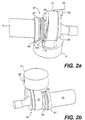
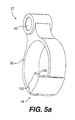
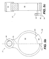
- mechanical system 84 includes an eccentric crankpin 14, an eccentric cam 16, and a connecting rod 27.
- eccentric crankpin 14 is formed as part of crankshaft 15 and has an eccentricity 18.
- eccentric cam 16 is includes an opening 101 in which crankpin 14 is rotatably disposed and has an eccentricity 19.
- crankpin 27 includes an opening 92 in which eccentric cam 16 is rotatably disposed.
- connecting rod 27 is connected to piston 8 by a wrist pin 28. This connection allows connecting rod 27 to pivot with respect to piston 8. It is contemplated that other, similar connecting devices will be readily apparent to one skilled in the art.
- the mechanical system also includes a first stop mechanism for restricting the relative rotation of the eccentric cam about the crankpin when the motor is rotating the crankshaft in the forward direction and a second stop mechanism for restricting the relative rotation of the eccentric cam with respect to the connecting rod when the motor is rotating the crankshaft in the reverse direction.
- a first stop mechanism for restricting the relative rotation of the eccentric cam about the crankpin when the motor is rotating the crankshaft in the forward direction
- a second stop mechanism for restricting the relative rotation of the eccentric cam with respect to the connecting rod when the motor is rotating the crankshaft in the reverse direction.
- the first stop mechanism includes a stop 110 positioned on crankshaft 15 adjacent eccentric crankpin 14.
- eccentric cam 16 includes a first sloping projection 102 that ends in a face 104.
- stop 110 engages face 104 so that eccentric cam 16 is fixed with respect to eccentric crankpin 14.
- stop 110 rides along sloping projection 102, causing eccentric cam 16 to slide along crankpin 14, until stop 110 eventually drops over face 104.
- eccentric crankpin 14 is free to rotate within eccentric cam 16.
- the components of the first stop mechanism are disposed on crankshaft 15 and eccentric cam 16 so that when crankshaft 15 is rotated in the first direction and the eccentric cam is fixed with respect to the crankpin, the eccentricity 18 of crankpin 14 aligns with eccentricity 19 of eccentric cam 16.
- Figs. 13a - 13e illustrate the operation of the coupling structure in the full stroke mode.
- Crankpin 15 is rotated in the first direction as indicated by arrow 114.
- the combined eccentricity of cam 16 and crankpin 14 move connecting rod 27 and connected piston to the bottom position.
- Fig. 13c when crankpin 14 is at the top of its rotation, the combined eccentricity of cam 16 and crankpin 14 move connecting rod 27 and connected piston to the top dead center position.
- the second stop mechanism includes a second sloping projection 106 on eccentric cam 16, preferably on the opposite side of the eccentric cam from first sloping projection 102.
- Second sloping projection 106 ends in face 108.
- connecting rod 27 includes a stop 94 having two support members 96 and 98 that form an L-shape extending away from and over opening 92.
- Support member 98 includes two faces 100 and 102.
- the first stop mechanism fixes eccentric cam 16 to crankpin 14 and the eccentric cam rotates within connecting rod 27.
- face 102 of stop 94 rides along sloping projection 106, thereby causing eccentric cam 16 to slide along crankpin 14.
- face 102 of stop 94 moves over face 108 of sloping projection 106.
- the first stop mechanism disengages and crankpin 14 rotates freely within eccentric cam 16.
- the eccentric cam will rotate in the reverse direction with respect to connecting rod 27 until face 108 of sloping projection 106 on eccentric cam 16 engages stop 94 on connecting rod 27. This engagement will restrict the rotation of the eccentric cam with respect to the connecting rod when the crankshaft is rotated in the reverse direction.
- a spring 88 and a collar 89 are positioned on crankshaft 15.
- Spring 88 and collar 89 rotate with crankshaft 15.
- Spring 88 acts through collar 89 to bias eccentric cam 16 along crankpin 14.
- the action of spring ensures that faces 104 and 108 on eccentric cam 16 will align with and engage stops 110 and 94 on crankshaft 15 and connecting rod 27, respectively when the rotational direction of crankshaft 15 is switched. It is contemplated that the sizing and tolerances of the components of the mechanical system may be such that spring 88 and collar 89 may be omitted and the acceleration forces generated when the motor is reversed will ensure that the first and second stop mechanisms will still engage the respective stops on the connecting rod and crankshaft.
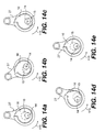
- Figs. 14a - 14e illustrate the operation of the coupling structure in the reduced stroke mode.
- Crankpin 15 is rotated in the reverse direction as indicated by arrow 115.
- Figs 14a - 14e depict the opposite side of the coupling structure from Figs. 13a - 13e.
- the components of the second stop mechanism are disposed on eccentric cam 16 and connecting rod 27 so that when crankshaft 15 is rotated in the reverse direction the eccentricity 18 of eccentric cam 16 aligns with an axis 23 of connecting rod 27.
- the eccentricity 19 of the crankpin will only align with eccentricity18 of the eccentric cam when crankpin14 is at the top of its rotation.
- this alignment results in the piston reaching the top dead center position when operating in the half stroke mode.
- the eccentricity of cam 16 is opposite the eccentricity of crankpin 14.
- the piston only moves to an intermediate position, and not to the bottom position.
- the stroke length of the reduced stroke operation may be altered by varying the eccentricities 18 and 19 of the eccentric cam and crankpin, respectively.
- eccentric cam 16 may include a projection 120 having a face 122.
- Connecting rod 27 may include a sloping projection 123 ending in a stop 124.
- projection 120 on eccentric cam will ride along and over sloping projection 120 on connecting rod 27.
- face 122 of eccentric cam will engage stop 124 on connecting rod 27, thereby preventing the eccentric cam from rotating with respect to the connecting rod.
- Figs. 7 and 8 illustrate another exemplary embodiment of the first and second stop mechanisms.
- This embodiment of the coupling structure is generally designated 12 and is shown in connection with a refrigerator compressor having a piston 8 mounted in a cylinder 9, and having a reed type discharge valve 21 mounted on a valve plate 10 having a discharge port 11 therethrough.
- the first stop means 20 comprises cooperating shoulder means such as pin 30 on eccentric cam 16 and shoulder 32 machined into crankpin 14, and wherein said second stop means 24 comprises cooperating shoulder means such as pin 34 on connecting rod 27 and shoulder 36 machined into eccentric cam 16.
- the pins 30 and 34 are continually urged radially inwardly from their sockets 38 by compression springs 40.
- a leaf-type spring or equivalent structure 42 is affixed by screw 44 or the like in a slot 43 machined into connecting rod 27 and is normally sprung into slot 46 machined into eccentric cam 16.
- spring 42 is flexed radially outwardly in to slot 43.
- spring 42 and slot 46 can be dimensioned such that the spring does not strike against the slot floor 48 upon each counterclockwise orbit of the crankpin and eccentric cam and create objectionable clicking sound.
- the radius 50 of the exit from slot 46 further reduces or eliminates any noise created by contact of spring 42 with the eccentric cam.
- Such structure can also be used for the crankpin to eccentric cam junction.
- a stop arm generally designated 52 is affixed to a sleeve 63 rotatably mounted on crankpin 14 within a recess 54 in a face 55 of eccentric cam 16.
- Arm 52 is comprised of an inner section 56 affixed to sleeve 53 and an outer stop section 58 providing a stop end 59. Sections 56 and 58 are pivotally connected by a hinge pin 60.
- a light spring 76 affixed to the top of one of the sections 56 or 58 and slidable on the other may be used to urge section 58 downwardly (as viewed in the drawing) to assist in its insertion into socket 74.
- Other springs such as a torsional spring mounted over an extension of pivot pin 60 may also be used.
- crankpin 14 moves alone thru its orbit during reduced stroke the cam eccentricity 19 will be swung back and forth to each side of the piston stroke axis 25, but as indicated by the approximate dotted lines 23, the cam eccentricity will remain substantially aligned with the connecting rod axis 23.
- the present invention in its broad sense is not limited to the use of any particular type of stop structure and the components of the stops shown herein can be reverse mounted, e.g., the spring 40 and pin 34 can be mounted in the cam bushing and the shoulder 36 cut into the bearing.
- the eccentricities of the eccentric cam and the crankpin are substantially equal whereby the cylinder capacity can be switched from full to substantially one half upon reversing the crankshaft rotation.
- first and second stop means or stop mechanisms may be positioned at any angular position around the crankpin and eccentric cam, and around the eccentric cam and connecting rod respectively as long as the two eccentricities are aligned for full stroke, and the bushing eccentricity is substantially aligned with the connecting rod stroke axis for the reduced stroke.
- first stop mechanism 130 and second stop mechanism 132 are preferably offset from connecting rod axis 23.
- first stop mechanism has a tendency to become unstable just after the piston passes top dead center. If first stop mechanism 130 is offset as shown in Fig. 15a, the forces that create the instability will act on eccentric cam 16 to move the eccentric cam into connection with the stop on the crankshaft, thereby removing the instability.
- second stop mechanism 132 is preferably advanced as shown in Fig. 15b to prevent any unstable conditions.
- a unique electrical circuit has been developed for controlling the reversible motor and may be employed in a preferred embodiment of the invention as described below in connection with a single cylinder compressor, the circuit being shown schematically in Figs. 16 and 17.
- the control schematic of Fig. 16 is equivalent to industry conventional PSC (permanent, split capacitor) wiring schematics using predetermined power supply.
- Line I runs through the common terminal (C) which leads into the motor protection. After leaving the motor protection, the current flow will split, going through both the start (S) and main, i.e., run (R) windings with M (motor) High contactor closed. This stage will be using the run winding as the main winding and places the run capacitor in series with the start winding, obtaining standard motor rotation with the piston fully active, i.e., full capacity operation.
- the present unique Control Schematic of Fig. 17 employs a predetermined power supply depending on application.
- Line one will run through the common terminal (C), which leads to the motor protection.
- the current flow separates going through both the original start and original main windings with M low contactor energized.
- the compressor will now be using the start winding as the main and placing the run capacitor in series with the original main winding. Run capacitor placement in this mode facilitates both motor and mechanical rotation changes and simultaneously reduces motor strength to match the resulting reduced piston stroke, thus maximizing motor efficiency for the reduced load.
- the original main winding and start capacitor, in reduced compressor capacity mode may be taken offline by a centrifugal switch or the like after the motor attains operational speed.
- Suitable exemplary solenoid actuated contactors or switches for use as the "switching means" of the present invention are shown and described in the General Electric, Product information brochure GEA -115408 4/87 ISM 1800, entitled “Definite Purpose Controls", 23 pages, the disclosure of which is hereby incorporated herein by reference in its entirety.
- the power unit would employ the following structures and operating characteristics:
- the compressor would have substantially the following structure and operating characteristics:
- refrigeration cycle 143 includes a condenser 148, an expansion device 146, an evaporator 152, and a two-stage reciprocating compressor 150.
- a refrigerant is circulated through the refrigeration cycle.
- the capacity of compressor 150 directly affects the amount of cooling provided by the refrigerant in the evaporator.
- compressor 150 operates at full capacity and provides maximum cooling to the evaporator.
- the two stage reciprocating compressor is operated in the reduced stroke mode, the amount of cooling provided to the evaporator is similarly reduced.
- refrigeration cycle 143 may be used in a heating, ventilating, and air conditioning (“HVAC") system.
- HVAC heating, ventilating, and air conditioning
- the HVAC system is used to condition the air in an enclosure 156. Air is circulated through the HVAC unit 154 through supply duct 160 and return duct 166 by a blower 164. Blower 164 passes air over the evaporator of the refrigeration cycle to cool the air before the air enters the room.
- a temperature sensor 158 is positioned within enclosure 156.
- sensor 158 determines the temperature of enclosure has risen above a preset limit
- sensor 158 activates the compressor in either the full stroke mode or the reduced stroke mode depending upon the sensed temperature of the air. Operating the compressor at the appropriate capacity depending upon the current conditions of the room will improve the overall efficiency of the system. It is contemplated that the present invention may be used in other air conditioning systems, such as heat pumps, or the like.
- a refrigerator 140 includes at least one insulated cooling compartment 144.
- a temperature sensor 142 is positioned inside compartment 144.
- the compressor may be operated in either the full stroke or reduced stroke mode.
- the compressor is continuously operated in the reduced stroke mode until a high cooling demand, such as opening the door or introducing a load of relatively warm perishables, is placed on the refrigerator.
- a high cooling demand such as opening the door or introducing a load of relatively warm perishables
Landscapes
- Engineering & Computer Science (AREA)
- Mechanical Engineering (AREA)
- General Engineering & Computer Science (AREA)
- Compressor (AREA)
- Control Of Positive-Displacement Pumps (AREA)
- Compressors, Vaccum Pumps And Other Relevant Systems (AREA)
- Transmission Devices (AREA)
- Applications Or Details Of Rotary Compressors (AREA)
Description
Claims (10)
- A two stage reciprocating compressor comprising a block (82) with a cylinder (9) and associated compression chamber and piston (8), a reversible motor (86) for rotating in a forward and a reverse direction, and a mechanical system (84) disposed between the motor (86) and the piston (8), the mechanical system (84) including a crankshaft (15) connected to the reversible motor (86) for rotation in a forward direction and a reverse direction, an eccentric crankpin (14) formed on the crankshaft (15), and a connecting rod (27) connected to the piston (8), characterized in that the mechanical system (84) further includes an eccentric, two position cam (16) rotatably mounted on said eccentric crankpin (14) and linking said eccentric crankpin (14) to the connecting rod (27), said eccentric, two position cam (16) configured to engage and rotate with said eccentric crankpin (14) when the crankshaft (15) is rotated in the forward direction to drive the piston (8) at a full stroke between a bottom position and a top dead center position, said eccentric, two position cam (16) further configured to engage the connecting rod (27) when the crankshaft (15) is rotated in the reverse direction to drive the piston (8) at a reduced stroke between an intermediate position and the top dead center position.
- The compressor of claim 1, further including a control for selectively operating said motor (86) either in the forward direction at a first preselected, fixed speed or in the reverse direction at a second preselected, fixed speed.
- The compressor of claim 1, wherein the eccentricities of said eccentric crankpin (14) and said eccentric, two position cam (16) combine to cause the piston (8) to have the full stroke when the motor (86) is operated in the forward direction and to cause the piston (8) to have the reduced stroke when the motor (86) is operated in the reverse direction.
- The compressor of claim 1, wherein said eccentric, two position cam (16) is slidably mounted on said eccentric crankpin (14) and said eccentric, two position cam (16) slides axially along said eccentric crankpin (14) to engage one of said eccentric crankpin (14) and the connecting rod (27).
- The compressor of claim 1, wherein said eccentric, two position cam (16) includes a first sloping projection (102) having a first face (104) and a second sloping projection (106) having a second face (108), the first face (104) configured to engage said eccentric crankpin (14) when the crankshaft (15) is rotating in the forward direction and the second face (108) configured to engage the connecting rod (27) when the crankshaft (15) is rotating in the reverse direction.
- The compressor of claim 5, wherein said eccentric crankpin (14) includes a stop (110) and said connecting rod (27) includes a stop (94), said first face (104) engaging the stop (110) of said eccentric crankpin (14) to restrict the relative rotation of said eccentric, two position cam (16) about said eccentric crankpin (14) and said second face (108) engaging the stop (94) on the connecting rod (27) to restrict the rotation of said eccentric, two position cam (16) relative to the connecting rod (27) when the crankshaft (15) rotates in the reverse direction.
- The compressor of claim 6, further comprising a spring (88) biasing said eccentric, two position cam (16) axially along said eccentric crankpin (14) to align the first and second sloping projections (102, 106) of said eccentric, two position cam (16) with the stop (110) of said eccentric crankpin (14) and the stop (94) of the connecting rod (27).
- The compressor according to any one of claims 1 and 3, wherein the eccentricities of said eccentric, two position cam (16) and said eccentric crankpin (14) are chosen so that the capacity of the compressor is switched from full to approximately one half, upon reversing of the motor (86).
- A refrigerator appliance (140) including a compressor according to any one of claims 1 through 8.
- A heating, ventilating, and air conditioning ("HVAC") system for conditioning air in an enclosure (156) including a compressor according to any one of claims 1 through 8.
Applications Claiming Priority (3)
| Application Number | Priority Date | Filing Date | Title |
|---|---|---|---|
| US09/013,154 US6099259A (en) | 1998-01-26 | 1998-01-26 | Variable capacity compressor |
| US13154 | 1998-01-26 | ||
| PCT/US1999/001612 WO1999037920A2 (en) | 1998-01-26 | 1999-01-26 | Variable capacity compressor having adjustable crankpin throw structure |
Publications (3)
| Publication Number | Publication Date |
|---|---|
| EP1051571A2 EP1051571A2 (en) | 2000-11-15 |
| EP1051571A3 EP1051571A3 (en) | 2002-09-11 |
| EP1051571B1 true EP1051571B1 (en) | 2003-07-30 |
Family
ID=21758582
Family Applications (1)
| Application Number | Title | Priority Date | Filing Date |
|---|---|---|---|
| EP99904283A Expired - Lifetime EP1051571B1 (en) | 1998-01-26 | 1999-01-26 | Variable capacity compressor having adjustable crankpin throw structure |
Country Status (9)
| Country | Link |
|---|---|
| US (2) | US6099259A (en) |
| EP (1) | EP1051571B1 (en) |
| KR (1) | KR100719873B1 (en) |
| CN (1) | CN1129714C (en) |
| AU (1) | AU2471299A (en) |
| BR (1) | BR9907750A (en) |
| DE (1) | DE69909968T2 (en) |
| IL (1) | IL137486A (en) |
| WO (1) | WO1999037920A2 (en) |
Families Citing this family (39)
| Publication number | Priority date | Publication date | Assignee | Title |
|---|---|---|---|---|
| US6092993A (en) * | 1997-08-14 | 2000-07-25 | Bristol Compressors, Inc. | Adjustable crankpin throw structure having improved throw stabilizing means |
| US6446451B1 (en) | 1998-01-26 | 2002-09-10 | York International Corporation | Variable capacity compressor having adjustable crankpin throw structure |
| US6190137B1 (en) * | 1999-09-24 | 2001-02-20 | Tecumseh Products Company | Reversible, variable displacement compressor |
| KR100386604B1 (en) * | 2000-12-06 | 2003-06-02 | 엘지전자 주식회사 | double capacity compressor |
| WO2002097271A1 (en) * | 2001-06-01 | 2002-12-05 | Lg Electronics Inc. | Dual capacity compressor |
| US6663358B2 (en) * | 2001-06-11 | 2003-12-16 | Bristol Compressors, Inc. | Compressors for providing automatic capacity modulation and heat exchanging system including the same |
| KR100413452B1 (en) * | 2001-09-04 | 2003-12-31 | 엘지전자 주식회사 | Method for controlling of a motor for compressor having variable capacity |
| US6619926B2 (en) * | 2001-09-12 | 2003-09-16 | Tecumseh Products Company | Cam and crank engagement for a reversible, variable displacement compressor and a method of operation therefor |
| BR0116926B1 (en) * | 2001-12-17 | 2010-06-01 | crankshaft on a dual capacity compressor. | |
| KR100487962B1 (en) * | 2002-10-31 | 2005-05-06 | 엘지전자 주식회사 | Latching mechanism of dual capacity compressor |
| US6742441B1 (en) | 2002-12-05 | 2004-06-01 | Halliburton Energy Services, Inc. | Continuously variable displacement pump with predefined unswept volume |
| US20040241010A1 (en) * | 2003-03-27 | 2004-12-02 | Samsung Electronics Co., Ltd. | Variable capacity rotary compressor |
| CN100375881C (en) * | 2003-05-22 | 2008-03-19 | 乐金电子(天津)电器有限公司 | Apparatus and method for controlling operation of electric refrigerator utilizing forward or backward rotary compressor |
| CN100378327C (en) * | 2003-06-27 | 2008-04-02 | 乐金电子(天津)电器有限公司 | Locking device for dual capacity compressor |
| KR20050004392A (en) * | 2003-07-02 | 2005-01-12 | 삼성전자주식회사 | Capacity-Variable Type Rotary Compressor |
| US6925823B2 (en) * | 2003-10-28 | 2005-08-09 | Carrier Corporation | Refrigerant cycle with operating range extension |
| US7984617B2 (en) * | 2003-10-29 | 2011-07-26 | Lg Electronics Inc. | Method of controlling compressor for refrigerator and apparatus thereof |
| RU2329440C2 (en) * | 2003-10-29 | 2008-07-20 | ЭлДжи ЭЛЕКТРОНИКС ИНК. | Method for controlling refrigerator compressor and device for implementing thereof |
| KR100747566B1 (en) * | 2003-12-20 | 2007-08-08 | 엘지전자 주식회사 | Dual capacity compressor |
| US7674096B2 (en) * | 2004-09-22 | 2010-03-09 | Sundheim Gregroy S | Portable, rotary vane vacuum pump with removable oil reservoir cartridge |
| US7374406B2 (en) * | 2004-10-15 | 2008-05-20 | Bristol Compressors, Inc. | System and method for reducing noise in multi-capacity compressors |
| USD536711S1 (en) | 2004-12-13 | 2007-02-13 | Gregory S. Sundheim | Portable, refrigerant recovery unit |
| US7878081B2 (en) * | 2004-12-13 | 2011-02-01 | Gregory S Sundheim | Portable, refrigerant recovery unit |
| CN102379684B (en) | 2005-04-28 | 2014-11-19 | 普罗透斯数字保健公司 | Pharma-informatics system |
| US8836513B2 (en) | 2006-04-28 | 2014-09-16 | Proteus Digital Health, Inc. | Communication system incorporated in an ingestible product |
| US8912908B2 (en) | 2005-04-28 | 2014-12-16 | Proteus Digital Health, Inc. | Communication system with remote activation |
| KR100690893B1 (en) | 2005-08-11 | 2007-03-09 | 엘지전자 주식회사 | Dual Capacity Reciprocating Compressor |
| US7980831B2 (en) * | 2006-05-31 | 2011-07-19 | Hitachi, Ltd. | Oscillating type compressor |
| US9270025B2 (en) | 2007-03-09 | 2016-02-23 | Proteus Digital Health, Inc. | In-body device having deployable antenna |
| US8113805B2 (en) | 2007-09-26 | 2012-02-14 | Torad Engineering, Llc | Rotary fluid-displacement assembly |
| US20090277197A1 (en) * | 2008-05-01 | 2009-11-12 | Gambiana Dennis S | Evaporator apparatus and method for modulating cooling |
| EP3395333A1 (en) | 2009-01-06 | 2018-10-31 | Proteus Digital Health, Inc. | Pharmaceutical dosages delivery system |
| US9080569B2 (en) * | 2009-01-22 | 2015-07-14 | Gregory S. Sundheim | Portable, rotary vane vacuum pump with automatic vacuum breaking arrangement |
| US9149423B2 (en) | 2009-05-12 | 2015-10-06 | Proteus Digital Health, Inc. | Ingestible event markers comprising an ingestible component |
| BRPI0904208B1 (en) * | 2009-10-21 | 2019-04-16 | Embraco Indústria De Compressores E Soluções E Refrigeração Ltda. | DATA AND COMMAND COMMUNICATION SYSTEM AND METHOD BETWEEN VARIABLE CAPACITY COMPRESSOR AND ELECTRONIC THERMOSTAT FOR A COOLING AND COOLING SYSTEM. |
| CN102114286B (en) * | 2009-12-31 | 2014-06-11 | 北京谊安医疗系统股份有限公司 | Moving method of piston mechanism |
| EP2628942B1 (en) * | 2012-02-14 | 2014-10-01 | Continental Automotive GmbH | Pump and common rail fuel injection system |
| WO2014088695A1 (en) * | 2012-12-06 | 2014-06-12 | Carrier Corporation | Discharge reed valve for reciprocating refrigeration compressor |
| WO2017048571A1 (en) | 2015-09-14 | 2017-03-23 | Torad Engineering Llc | Multi-vane impeller device |
Family Cites Families (36)
| Publication number | Priority date | Publication date | Assignee | Title |
|---|---|---|---|---|
| US1315498A (en) | 1919-09-09 | Carryall trailer-vehicle | ||
| CA1015983A (en) * | 1974-08-28 | 1977-08-23 | Inco Limited | Double-eccentric variable drive system |
| US4245966A (en) * | 1978-01-30 | 1981-01-20 | Westinghouse Electric Corp. | Reciprocating piston device with changeable stroke length |
| US4242626A (en) * | 1978-08-15 | 1980-12-30 | Jet Spray Cooler, Inc. | AC Motor drive |
| US4236874A (en) * | 1979-03-02 | 1980-12-02 | Westinghouse Electric Corp. | Dual capacity compressor with reversible motor and controls arrangement therefor |
| US4248053A (en) * | 1979-03-05 | 1981-02-03 | Westinghouse Electric Corp. | Dual capacity compressor with reversible motor and controls arrangement therefor |
| AU7812181A (en) * | 1980-12-11 | 1982-06-17 | Card-O-Matic Pty. Limited | Speed changing of electric motors |
| US4396359A (en) * | 1981-07-20 | 1983-08-02 | Carrier Corporation | Motor compressor unit |
| DE3138812A1 (en) * | 1981-09-30 | 1983-04-14 | L. Schuler GmbH, 7320 Göppingen | Eccentric drive with stroke adjustment |
| US4409532A (en) * | 1981-11-06 | 1983-10-11 | General Electric Company | Start control arrangement for split phase induction motor |
| US4503371A (en) * | 1982-10-21 | 1985-03-05 | Tsudakoma Kogyo Kabushiki Kaisha | Mass driver circuit for weaving looms |
| US4479419A (en) * | 1982-11-02 | 1984-10-30 | Westinghouse Electric Corp. | Dual capacity reciprocating compressor |
| US4494447A (en) * | 1982-11-02 | 1985-01-22 | Westinghouse Electric Corp. | Self-latching eccentric cam for dual stroke compressor or pump |
| KR930004379B1 (en) * | 1983-11-16 | 1993-05-27 | 가부시끼가이샤 히다찌세이사꾸쇼 | Refrigerator controls |
| US4598764A (en) * | 1984-10-09 | 1986-07-08 | Honeywell Inc. | Refrigeration heat pump and auxiliary heating apparatus control system with switchover during low outdoor temperature |
| US4879502A (en) * | 1985-01-28 | 1989-11-07 | Hitachi, Ltd. | Speed control apparatus and method for motors |
| JPS6273068A (en) * | 1985-09-25 | 1987-04-03 | 株式会社日立製作所 | How to control the refrigerator |
| US5252905A (en) * | 1985-12-23 | 1993-10-12 | York International Corporation | Driving system for single phase A-C induction motor |
| US4687982A (en) * | 1986-02-27 | 1987-08-18 | Pt Components, Inc. | Instant reversing circuit |
| US4767293A (en) * | 1986-08-22 | 1988-08-30 | Copeland Corporation | Scroll-type machine with axially compliant mounting |
| US4838769A (en) * | 1988-01-25 | 1989-06-13 | Tecumseh Products Company | High side scotch yoke compressor |
| US4963075A (en) * | 1988-08-04 | 1990-10-16 | The Charles Machine Works, Inc. | Radial diaphragm pump |
| US5106278A (en) * | 1988-09-21 | 1992-04-21 | Bristol Compressors, Inc. | Refrigerant gas compressor construction |
| US5203857A (en) * | 1990-06-01 | 1993-04-20 | Bristol Compressors, Inc. | Gas compressor head and discharge valve construction |
| US5080130A (en) * | 1990-06-01 | 1992-01-14 | Bristol Compressors, Inc. | Gas compressor head and discharge valve construction |
| JPH04236874A (en) * | 1991-01-17 | 1992-08-25 | Bridgestone Corp | Flow rate regulating valve |
| US5129792A (en) * | 1991-01-25 | 1992-07-14 | General Motors Corporation | Refrigerant compressor having gas pulsation suppression device |
| US5070932A (en) * | 1991-02-20 | 1991-12-10 | Lennox Industries Inc. | Thermostat with enhanced outdoor temperature anticipation |
| BR9102288A (en) * | 1991-05-28 | 1993-01-05 | Brasileira S A Embraco Empresa | SUCTION DIFFERENT SET FOR HERMETIC COMPRESSOR |
| DE69210564T2 (en) * | 1991-12-02 | 1996-10-02 | Aida Eng Ltd | Device for adjusting the ram stroke on a press |
| US5592058A (en) * | 1992-05-27 | 1997-01-07 | General Electric Company | Control system and methods for a multiparameter electronically commutated motor |
| DE4322223A1 (en) * | 1993-07-03 | 1995-01-12 | Ako Werke Gmbh & Co | Regulating device (control device) for a compressor motor of a refrigerator and/or freezer |
| GB2289958A (en) * | 1994-06-01 | 1995-12-06 | Sanyo Electric Co | Air conditioning control circuit |
| US5780990A (en) * | 1997-03-06 | 1998-07-14 | Weber; Harold J. | Parasynchronous induction motor control method and apparatus |
| US6092993A (en) * | 1997-08-14 | 2000-07-25 | Bristol Compressors, Inc. | Adjustable crankpin throw structure having improved throw stabilizing means |
| US5951261A (en) * | 1998-06-17 | 1999-09-14 | Tecumseh Products Company | Reversible drive compressor |
-
1998
- 1998-01-26 US US09/013,154 patent/US6099259A/en not_active Expired - Lifetime
-
1999
- 1999-01-22 US US09/235,288 patent/US6217287B1/en not_active Expired - Lifetime
- 1999-01-26 WO PCT/US1999/001612 patent/WO1999037920A2/en not_active Ceased
- 1999-01-26 CN CN99803424A patent/CN1129714C/en not_active Expired - Fee Related
- 1999-01-26 BR BR9907750-7A patent/BR9907750A/en not_active IP Right Cessation
- 1999-01-26 AU AU24712/99A patent/AU2471299A/en not_active Abandoned
- 1999-01-26 DE DE69909968T patent/DE69909968T2/en not_active Expired - Fee Related
- 1999-01-26 EP EP99904283A patent/EP1051571B1/en not_active Expired - Lifetime
- 1999-01-26 IL IL13748699A patent/IL137486A/en not_active IP Right Cessation
- 1999-01-26 KR KR1020007008163A patent/KR100719873B1/en not_active Expired - Fee Related
Also Published As
| Publication number | Publication date |
|---|---|
| IL137486A0 (en) | 2001-07-24 |
| KR20010034401A (en) | 2001-04-25 |
| BR9907750A (en) | 2001-09-04 |
| US6099259A (en) | 2000-08-08 |
| DE69909968D1 (en) | 2003-09-04 |
| CN1129714C (en) | 2003-12-03 |
| EP1051571A3 (en) | 2002-09-11 |
| AU2471299A (en) | 1999-08-09 |
| US6217287B1 (en) | 2001-04-17 |
| IL137486A (en) | 2004-06-01 |
| DE69909968T2 (en) | 2004-03-04 |
| WO1999037920A3 (en) | 2000-12-28 |
| EP1051571A2 (en) | 2000-11-15 |
| KR100719873B1 (en) | 2007-05-18 |
| WO1999037920A2 (en) | 1999-07-29 |
| CN1300348A (en) | 2001-06-20 |
Similar Documents
| Publication | Publication Date | Title |
|---|---|---|
| US6217287B1 (en) | Variable capacity compressor having adjustable crankpin throw structure | |
| US6172476B1 (en) | Two step power output motor and associated HVAC systems and methods | |
| JP4242661B2 (en) | Rotary compressor | |
| US6446451B1 (en) | Variable capacity compressor having adjustable crankpin throw structure | |
| US8186979B2 (en) | Capacity varying type rotary compressor and refrigeration system having the same | |
| US6331925B1 (en) | Two stage reciprocating compressors and associated HVAC systems and methods | |
| CN100386523C (en) | air conditioner | |
| TW397902B (en) | Fluid flow control mechanism and slant plate-type compressor | |
| KR101738458B1 (en) | High pressure compressor and refrigerating machine having the same | |
| JP2000110734A (en) | Hybrid compressor and its control system | |
| US6040679A (en) | Variable capacity compressor having two-step motor strength adjustability | |
| WO2015162780A1 (en) | Heat pump device | |
| KR970001753B1 (en) | Oscillating plate type compressor with variable capacity mechanism | |
| US20040184922A1 (en) | Rotary compressor | |
| US6024547A (en) | Power-variable compressor and air conditioner using the same | |
| JP4594301B2 (en) | Hermetic rotary compressor | |
| JPH09250484A (en) | compressor | |
| JP4061730B2 (en) | Variable capacity swash plate compressor | |
| US6276154B1 (en) | Two step metering device | |
| KR20180094408A (en) | High pressure compressor and refrigerating machine having the same | |
| JP2005344683A (en) | Hermetic compressor | |
| KR20060065801A (en) | Air conditioner | |
| KR100664293B1 (en) | Capacity variable device of rotary compressor and air conditioner | |
| JP2023013210A (en) | rotary compressor and air conditioner | |
| EP0205670A1 (en) | Refrigerating or heat-pump system |
Legal Events
| Date | Code | Title | Description |
|---|---|---|---|
| PUAI | Public reference made under article 153(3) epc to a published international application that has entered the european phase |
Free format text: ORIGINAL CODE: 0009012 |
|
| 17P | Request for examination filed |
Effective date: 20000824 |
|
| AK | Designated contracting states |
Kind code of ref document: A2 Designated state(s): BE DE GB |
|
| PUAK | Availability of information related to the publication of the international search report |
Free format text: ORIGINAL CODE: 0009015 |
|
| 17Q | First examination report despatched |
Effective date: 20020614 |
|
| AK | Designated contracting states |
Kind code of ref document: A3 Designated state(s): BE DE GB |
|
| GRAH | Despatch of communication of intention to grant a patent |
Free format text: ORIGINAL CODE: EPIDOS IGRA |
|
| GRAH | Despatch of communication of intention to grant a patent |
Free format text: ORIGINAL CODE: EPIDOS IGRA |
|
| GRAA | (expected) grant |
Free format text: ORIGINAL CODE: 0009210 |
|
| AK | Designated contracting states |
Designated state(s): BE DE GB |
|
| REG | Reference to a national code |
Ref country code: GB Ref legal event code: FG4D |
|
| XX | Miscellaneous (additional remarks) |
Free format text: DERZEIT SIND DIE WIPO-PUBLIKATIONSDATEN A3 NICHT VERFUEGBAR. |
|
| REF | Corresponds to: |
Ref document number: 69909968 Country of ref document: DE Date of ref document: 20030904 Kind code of ref document: P |
|
| PLBE | No opposition filed within time limit |
Free format text: ORIGINAL CODE: 0009261 |
|
| STAA | Information on the status of an ep patent application or granted ep patent |
Free format text: STATUS: NO OPPOSITION FILED WITHIN TIME LIMIT |
|
| 26N | No opposition filed |
Effective date: 20040504 |
|
| PGFP | Annual fee paid to national office [announced via postgrant information from national office to epo] |
Ref country code: GB Payment date: 20070108 Year of fee payment: 9 |
|
| PGFP | Annual fee paid to national office [announced via postgrant information from national office to epo] |
Ref country code: BE Payment date: 20070109 Year of fee payment: 9 |
|
| PGFP | Annual fee paid to national office [announced via postgrant information from national office to epo] |
Ref country code: DE Payment date: 20070305 Year of fee payment: 9 |
|
| BERE | Be: lapsed |
Owner name: *BRISTOL COMPRESSORS INC. Effective date: 20080131 |
|
| GBPC | Gb: european patent ceased through non-payment of renewal fee |
Effective date: 20080126 |
|
| PG25 | Lapsed in a contracting state [announced via postgrant information from national office to epo] |
Ref country code: DE Free format text: LAPSE BECAUSE OF NON-PAYMENT OF DUE FEES Effective date: 20080801 |
|
| PG25 | Lapsed in a contracting state [announced via postgrant information from national office to epo] |
Ref country code: GB Free format text: LAPSE BECAUSE OF NON-PAYMENT OF DUE FEES Effective date: 20080126 |
|
| PG25 | Lapsed in a contracting state [announced via postgrant information from national office to epo] |
Ref country code: BE Free format text: LAPSE BECAUSE OF NON-PAYMENT OF DUE FEES Effective date: 20080131 |