EP1050994A2 - Verfahren zur Unterstützung der Kommunikation zwischen Netzelementen und Netzelement-Managern - Google Patents
Verfahren zur Unterstützung der Kommunikation zwischen Netzelementen und Netzelement-Managern Download PDFInfo
- Publication number
- EP1050994A2 EP1050994A2 EP00440114A EP00440114A EP1050994A2 EP 1050994 A2 EP1050994 A2 EP 1050994A2 EP 00440114 A EP00440114 A EP 00440114A EP 00440114 A EP00440114 A EP 00440114A EP 1050994 A2 EP1050994 A2 EP 1050994A2
- Authority
- EP
- European Patent Office
- Prior art keywords
- functional units
- network element
- converter unit
- network
- semantics
- Prior art date
- Legal status (The legal status is an assumption and is not a legal conclusion. Google has not performed a legal analysis and makes no representation as to the accuracy of the status listed.)
- Withdrawn
Links
Images

Classifications
-
- H—ELECTRICITY
- H04—ELECTRIC COMMUNICATION TECHNIQUE
- H04L—TRANSMISSION OF DIGITAL INFORMATION, e.g. TELEGRAPHIC COMMUNICATION
- H04L41/00—Arrangements for maintenance, administration or management of data switching networks, e.g. of packet switching networks
- H04L41/02—Standardisation; Integration
- H04L41/0226—Mapping or translating multiple network management protocols
-
- H—ELECTRICITY
- H04—ELECTRIC COMMUNICATION TECHNIQUE
- H04L—TRANSMISSION OF DIGITAL INFORMATION, e.g. TELEGRAPHIC COMMUNICATION
- H04L41/00—Arrangements for maintenance, administration or management of data switching networks, e.g. of packet switching networks
- H04L41/04—Network management architectures or arrangements
- H04L41/052—Network management architectures or arrangements using standardised network management architectures, e.g. telecommunication management network [TMN] or unified network management architecture [UNMA]
Definitions
- the invention relates to a converter unit to support the Communication between at least one network element and at least one a network element manager still the preamble of claim 1, and a procedure to support communication between at least a network element and at least one network element manager the preamble of claim 11.
- the invention is based on the usual structure of a network management system for telecommunications networks, such as that in the Article "Telecommunications Management Network (TMN): Architecture, Interfaces and applications, ntz vol. 43, number 6, 1990 by Rüdiger Falkner and Harald Müllner is described.
- TTN Transmission Management Network
- a network management center is connected via a communication network connected to the network elements to be controlled.
- Network elements can do this of different types of mediation or transmission facilities are formed, which over have different network management interfaces, for example via Q1, Q2 or Q3 interfaces.
- Adaptation devices (mediation device) between the Network management center and the network elements provided.
- This Adaptation devices provide a converter function for the Communication between the respective associated with it Network elements and the network element managers assigned to these network elements the network management center.
- This converter function cannot just convert communication protocols include, but can also be an information model conversion require. An example of this is a conversion of a manufacturer-specific Q3 interface into an operator-specific Q3 Interface.
- the converter function is here as an overall function developed to the respective requirements.
- the invention is based on the object, the communication between network elements and network element managers using a support powerful converter function.
- a converter unit for support the communication between at least one network element and at least one network element manager according to the teaching of claim 1, and a method to support communication between at least one network element and at least one network element manager according to the teaching of claim 11.
- the invention is based on the idea of converting Separate protocol functions from semantic functions and protocol functional units and to provide semantic functional units that interact with each other via uniform interfaces.
- Special protocol functional units exchange network management messages, assigned to a specific network management protocol are with a network element or a network element manager and edit the respective special network management protocol.
- the Semantic functional units form a representation based on a respective first semantics based on a representation based on a the respective second semantics and offer the respective mapping function the protocol functional units described above each for all first functional units have a uniform interface.
- the advantage of the invention is that rapid development powerful converter functions for communication between Network elements and network element managers is made possible. This advantage is particularly evident in network management systems that have a Many different network elements and therefore a large number different converter functions for communication between need these network elements and the network element managers. Further Advantages are the lower overall resulting from the invention Development effort, the ability to use software to a large extent reuse and the lower test effort.
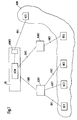
- the network management system has one Network control center OS, three converter units KON1 to KON3 and several network elements NE1 to NE5.
- the network elements NE1 to NE3 are with the converter unit via the communication networks KN1 or KN2 KON1 and the network element NE4 is via the communication network KN3 connected to the converter unit KON2.
- the converter units KON1 and KON2 are via the communication network KN5 and with the Network control center OS connected.
- the network element NE5 is about that Communication network KN4 connected to the network control center OS.
- ISDN Integrated Services Digital Network
- IP Internet Protocol
- the network element NE1 represents, for example, a switching node of the communication network KOM represents, for example an ISDN switching center
- SDH Synchronous Digital Hierarchy
- the converter units KON1 and KON2 are used to adapt the connected network elements to the network management center OS.
- the converter units KON1 and KON2 are each one or more connected via a communication medium Computer nodes formed.
- the computer nodes are, for example, by X.25, # 7, ethernet or token ring communication network or via a Software bus connected to each other.
- the computer node or the Computer nodes form a hardware platform consisting of processors, Storage devices and peripheral components on which one Software platform that, for example, an operating system and a Database system includes. Then put on this system platform
- Application programs based on the functions of each Provide converter unit KON1 or KON2. From a functional point of view provide the application programs u. a. a converter function for the Communication between the network management center OS and the network elements connected to the respective converter unit.
- the communication networks KN1 to KN5 are Data networks via which network management messages can be transmitted.
- the communication networks KN1 to KN5 are signaling networks, X.25 packet networks or IP networks.
- SNMP Simple Network Management Protocol
- the network control center OS is one or more via one Communication medium connected computer nodes formed.
- the Computer nodes are, for example, through X.25, # 7, Ethernet or Token-Ring Communication network or via a software bus connected.
- the computer node or the computer nodes form one Hardware platform consisting of processors, memory devices and peripheral components on which a software platform is based that for example an operating system and a database system. On this system platform then put a variety of Application programs on the functions of the network control center Provide OS. From a functional point of view, the network control center OS one or more network element managers, of which in FIG. 1 for example, a network element manager NEM is shown. Further points the Network control center OS from a functional point of view a converter unit KON3 on.
- the network element manager NEM communicates via the Communication networks KN1 to KN4 and the converter units KON1 to KON3 with the network elements NE1 and NE5 and exchanges with the Network elements NE1 and NE5 network management messages. By exchanging these network management messages The network element manager NEM monitors, manages and controls them network elements NE1 to NE5 connected to it.
- the KON3 converter unit as well as the converter units KON1 and KON2 Converter function for communication between the network element manager NEM and the network elements connected to it.
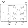
- Fig. 2 shows a section of the functional structure of the Converter unit KON1.
- the converter unit KON1 is connected to the via an interface INT1 Network elements NE1 to NE3 and via an interface INT2 with the Network element manager NEM connected.
- the converter unit KON1 has a control unit CDC and nine functional units SU1 to SU3, PU1 to PU3 and TU1 to TU3. It is of course also possible that the Converter unit KON1 via the interface INT1 with a different number is coupled by network elements.
- Object request brokers (ORB) provide one Infrastructure available that allows the objects, even in one distributed environment to communicate.
- the converter unit KON1 can on the one hand of one or several computer nodes and running on them Application programs are formed that the described here Execute converter function. On the other hand, the converter unit KON1 but also be formed by an application program itself, which at execute the converter function described here. Furthermore, the converter unit can also be read by a computer Storage medium with such, on the storage medium stored application program are formed.
- the Functional units SU1 to SU3, PU1 to PU3 and TU1 to TU3 each represent different groups of functional units. Each of these Groups of functional units can also have a different number of Functional units included, but at least one Functional unit to be present in each of the groups.
- the Functional units SU1 to SU3 of the first group are with the Functional units PU1 to PU3 of the second group via a uniform Interface CIN1 can be connected as required.
- the functional units PU1 to PU3 the second group are the functional units TU1 to TU3 third group can be coupled as required via a uniform interface CIN2.
- the interfaces CIN1 and CIN2 each provide one, for example Uniform API (Application Program Interface) or object interfaces through which all of those at the respective interface Functional units SU1 to SU3 and PU1 to PU3 or PU1 to PU3 and TU1 to TU3.
- Uniform API Application Program Interface
- object interfaces through which all of those at the respective interface Functional units SU1 to SU3 and PU1 to PU3 or PU1 to PU3 and TU1 to TU3.
- the functional units of the first group of functional units serve the semantic conversion. Semantics is the content, the meaning of Data and functions.
- the functional units of the second group of Functional units are used to convert network management protocols. These protocols are used to transport semantics. Syntax is the formal description, presentation of the semantics.
- the Protocol conversion corresponds to a conversion of the syntax of the data and functions of the respective network management protocol, i.e. one pure mapping of data structures.
- the functional units of the third Group of functional units are used to process Transport logs. It is also possible on this group of To waive functional units or their functions in Functional units of the second group of functional units integrate.
- the functional units of the first group each represent a special one Semantic conversion ready and the functional units of the second Groups each provide a special syntax conversion.
- On off Data and function existing information part is from a Functional unit of the second group via the interface CIN1 to a Functional unit of the first group passed, which then a semantic conversion undertakes and accordingly via the interface CIN1 returns the modified functional part.
- functional units of the second group each a syntax conversion between two different types Provide network management protocols (Fig. 3) or one Conversion of the syntax of the data and functions of each Execute network management protocol to a uniform syntax (Fig. 2). It is also possible that the functional units of the first Group each a semantics conversion between two specific ones Semantics (e.g. based on a specific manufacturer-specific Information model and a special operator-specific Information model) perform (Fig. 3) or a conversion of one perform specific to general semantics (Fig. 2). Both Possibilities can be combined as desired, depending on the combination then the number of functional units required for the provision of the Interact conversion.
- the functional units SU1 to SU3 represent semantic functional units They form a representation based on a respective first one Semantics on a representation based on a respective second Semantics and offer the respective mapping function
- Functional units PU1 to PU3 each have one for all functional units PU1 to PU3 uniform interface CIN1.
- the functional units SU1 to SU3 each represent different ones Semantic conversions ready.
- the functional unit SU2 provides for example, converting a representation based on the Semantics of a first manufacturer-specific information model on one Representation ready based on general semantics.
- the Functional unit SU3, for example, represents the conversion of a Representation based on the semantics of a second manufacturer-specific Information model based on a representation based on the general Semantics ready.
- the functional unit SU2 provides, for example Conversion of a representation based on the semantics of a operator-specific information model based on a representation ready on general semantics.
- the functional units SU1 to SU3 are about representation based on general semantics can be coupled and perform the respective mapping function regardless of underlying management protocols. Network elements and network element managers are thus on the Semantic level coupled.
- the one carried out by the functional units SU1 to SU3 The semantics, ie the meaning of the individual, become images Parameters of a data structure for themselves and in connection with the other parameters of the data structure and the structure of the data structure rated as such. It is quite the case with semantic conversion possible that a parameter of one structure into a variety of Parameters in the other structure or vice versa or that from the existence of a certain structure in one figure one or more parameters result in the other figure or vice versa. It is essential that the semantic conversion of the The meaning of the two figures remains, although the individual parameters and structures in accordance with the respective semantics have different meanings.
- the functional units PU1 to PU3 provide protocol functional units They exchange network management messages via a first interface, each with a special network management protocol are assigned, with a network element or a Network element manager and edit the respective special Network management protocol.e
- the functional units PU1 to PU3 each convert the Syntax of the data and functions of a respective network management protocol to a uniform syntax.
- Network management logs are the logs on the application level, based on the specific for each Management function necessary predefined functions on the Use the application level.
- Examples of network management protocols are the CMIP protocol or the SNMP protocol.
- the functional units TU1 to TU3 provide transport protocol functional units They work on different ones Transport protocols related to the transport of Network management protocol messages are used.
- the control unit CDC dynamically couples functional units of the first, second and third group of functional units to a respective one Communication between a network element and a network element manager through a customized conversion of the Support network management messages. To do this, it determines the conversion needs necessary for the respective communication and determines the functional units required for this conversion. Then it instantiates the determined ones for the respective communication Functional units and causes the necessary for the conversion Links within this set of functional units.
- the control unit CDC could also be dispensed with.
- the control unit CDC has the advantage that the converter unit KONlautomatic always provides the correct conversion when a new network element or a new network control center with the converter unit KON1 is connected.
- Fig. 3 shows a section of the functional structure of the Converter unit KON2.
- the converter unit KON2 is connected to the interface 1NT1 ' Network elements NE4 and via an interface INT2 'with the network element manager NEM connected.
- the converter unit KON2 has seven Functional units SU1 'to SU3', PU1 'to PU3' and TU4 and the Functional units TU1 and TU2. It is of course also possible that the Converter unit KON2 via the interface lNT1 'with another Number of network elements is coupled.
- the functional units SU1 'to SU3' of the converter unit KON2 are like the functional units SU1 to SU3 according to FIG. 2, with which Difference that they do not convert an image based on a specific semantics into a mapping into a general semantics perform, but already a mapping between two different ones perform specific semantics. An interaction between the Functional units SU 'to SU3' of the first group of Functional units are no longer required.
- the functional units PU1 'to PU3' of the converter unit KON2 are like the functional units PU1 to PU3 according to FIG. 2, with which Difference that the functional units PU1 to PU3 already one Syntax conversion between data and functions of two perform various network management protocols. in the In contrast to the exemplary embodiment according to FIG. 2, there is therefore only one Functional unit of the second group of functional units on the Conversion involved.
- the functional units TU1, TU2 and TU4 of the converter unit KON2 are how the functional units TU1 to TU3 of FIG. 2 constructed, with the Provided that the functional unit TU4 the communication protocols of the Communication network KN3 processed.
- the converter unit KON2 corresponds to the converter unit KON1 constructed according to FIG. 1.
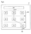
- Fig. 3 shows a section of the functional structure of the Network control center OS with the converter unit KON3 and Network element manager NEM.
- the converter unit KON3 is connected to the interface "INT1" Network elements NE5 and via an interface INT2 "with the Network element manager NEM connected.
- the converter unit KON3 has four functional units SU1 "to SU3" and TU4 and the functional units PU1 to PU3, TU1 and TU2. It is of course also possible that the Converter unit KON2 via the interface INT1 "with another Number of network elements is coupled.
- the functional units SU1 "to SU3" of the converter unit KON3 are like the functional units SU1 to SU3 according to FIG. 2, with which Difference that they do not convert an image based on a specific semantics into a mapping into a general semantics perform, but rather an illustration of a specific one Semantics in the semantics of the control of the network element manager carry out.
- An interaction between the functional units SU1 "to SU3 "of the first group of functional units is thus eliminated
- Functional units SU1 "to SU3" are directly with the network element manager NEM coupled in terms of control technology.
- the KON3 converter unit thus forms a ballast function for the network element manager that already all protocol processing functions as well as a semantics conversion for runs the Network Element Manager.
- the functional units PU1 to PU3 of the converter unit KON2 are after Fig. 2 constructed.
- the functional units TU1, TU2 and TU5 of the converter unit KON2 are how the functional units TU1 to TU3 of FIG. 2 constructed, with the Provided that the functional unit TU5 the communication protocols of the Communication network KN4 processed.
- the converter unit KON2 corresponds to the converter unit KON1 constructed according to FIG. 1.
- the converter unit KON3 it is also possible for the converter unit KON3 to control a Network element is integrated.
- the functional units SU1 would then each a mapping from a specific semantics to the semantics of the Perform control of the network element and would be control engineering coupled with the network element controller.
- the coupling could for example by accessing a group of status data and Control functions of the network element control are made possible.
- a further possibilities of coupling are the sending and the Receive messages to objects of the network element control.
- Another way of coupling is to send Messages to finite running in the network element control (State) machines (Finite State Machines) that run this Vending machines influence and eavesdropping on event messages sent by such machines.
- State network element control
- the functional units SU1 "to SU3" of FIG. 4 with the control of the Network element manager NEM are coupled.
Landscapes
- Engineering & Computer Science (AREA)
- Computer Networks & Wireless Communication (AREA)
- Signal Processing (AREA)
- Communication Control (AREA)
- Computer And Data Communications (AREA)
Abstract
Description
- Fig. 1
- zeigt ein Blockschaltbild eines Netzwerkmanagement-Systems mit mehreren erfindungsgemäßen Konvertereinheiten.
- Fig. 2
- zeigt eine funktionelle Darstellung einer Konvertereinheit nach Fig. 1 für ein erstes Ausführungsbeispiel.
- Fig. 3
- zeigt eine funktionelle Darstellung einer Konvertereinheit nach Fig. 1 für ein zweites Ausführungsbeispiel.
- Fig. 4
- zeigt eine funktionelle Darstellung einer Konvertereinheit nach Fig. 1 für ein viertes Ausführungsbeispiel.
Claims (11)
- Konvertereinheit (KON1 bis KON3) zur Unterstützung der Kommunikation zwischen mindestens einem Netzelement (NE1 bis NE5) und mindestens einem Netzelement-Manager (NEM), wobei die Konvertereinheit (KON1 bis KON3) mit einer ersten Schnittstelle (INT1, INT1', INT1") zur Kommunikation mit dem mindestens einen Netzelement und mit einer zweiten Schnittstelle (INT2, INT2', INT2") zur Kommunikation mit dem mindestens einen Netzelement-Manager (NEM) versehen ist, dadurch gekennzeichnet, daß die Konvertereinheit (KON1 bis KON3) mit ein oder mehreren ersten Funktionseinheiten (PU1 bis PU2; PU1' bis PU3') und mit diesen ersten Funktionseinheiten über eine einheitliche Schnittstelle (CIN1) verkoppelbaren ein oder mehreren zweiten Funktionseinheiten (SU1 bis SU3; SU1' bis SU3'; SU1" bis SU3") versehen ist, daß die ein oder mehreren ersten Funktionseinheiten (PU1 bis PU2; PU1' bis PU3') jeweils so ausgestaltet sind, daß sie über eine Schnittstelle Netzwerkmanagement-Nachrichten (CIN2), die einem jeweiligen speziellen Netzwerkmanagement-Protokoll zugeordnet sind, mit einem Netzelement oder einem Netzelement-Manager austauschen und das jeweilige spezielle Netzwerkmanagement-Protokoll bearbeiten, und daß die ein oder mehreren zweiten Funktionseinheiten (SU1 bis SU3; SU1' bis SU3'; SUl" bis SU3") jeweils so ausgestaltet sind, daß sie eine Darstellung basierend auf einer jeweiligen ersten Semantik auf eine Darstellung basierend auf einer jeweiligen zweiten Semantik abbilden und daß sie die jeweilige Abbildungsfunktion den ersten Funktionseinheiten (PU1 bis PU2; PU1' bis PU3') jeweils über die für alle ersten Funktionseinheiten einheitliche Schnittstelle (CIN1) anbietet.
- Konvertereinheit (KON1, KON3) nach Anspruch 1, dadurch gekennzeichnet, daß erste Funktionseinheiten (PU1 bis PU3) eine Konvertierung der Syntax der Daten und Funktionen des jeweiligen Netzwerkmanagement-Protokolls zu einer einheitlichen Syntax durchführen.
- Konvertereinheit (KON2) nach Anspruch 1, dadurch gekennzeichnet, daß erste Funktionseinheiten (PU1' bis PU3') eine Syntaxkonvertierung zwischen Daten und Funktionen zweier verschiedenartiger Netzwerkmanagement-Protokolle durchführen.
- Konvertereinheit (KON2) nach Anspruch 1, dadurch gekennzeichnet, daß die erste Semantik und die zweite Semantik der zweiten Funktionseinheiten (SU1' bis SU3) jeweils verschiedenartige, spezifische Semantika sind.
- Konvertereinheit (KON1) nach Anspruch 1, dadurch gekennzeichnet, daß die erste Semantik der zweiten Funktionseinheiten (SU1 bis SU3) eine spezifische Semantik und die zweite Semantik der zweiten Funktionseinheiten (SU1 bis SU3) eine allgemeine Semantik ist und zweite Funktionseinheiten (SU1 bis SU3) über die die allgemeine Semantik miteinander verkoppelt sind.
- Konvertereinheit (KON1 bis KON3) nach Anspruch 1, dadurch gekennzeichnet, daß die Konvertereinheit (KON1 bis KON3) weiter über ein oder mehrere dritte Funktionseinheiten (TU1 bis TU5) verfügt, die eine Bearbeitung von Transportprotokollen durchführt, die Netzwerkmanagement-Nachrichten transportieren.
- Konvertereinheit (KON1) nach Anspruch 6, dadurch gekennzeichnet, daß die Konvertereinheit (KON1) weiter mit einer Steuereinheit (CDC) versehen ist, die so ausgestaltet ist, daß sie dynamisch erste, zweite und dritte Funktionseinheiten (SU1 bis SU3, PU1 bis PU3) zur Unterstützung der Kommunikation zwischen Netzelementen und Netzelement-Managern verkoppelt.
- Konvertereinheit (KON1, KON2) nach Anspruch 1, dadurch gekennzeichnet, daß die Konvertereinheit (KON1, KON2) über die erste Schnittstelle (INT1; INT1') und mindestens ein Kommunikationsnetz (KN1 bis KN3) mit dem mindestens einen Netzelement (NE1 bis NE4) verkoppelt ist und über die zweite Schnittstelle (INT2, INT2') und mindestens ein Kommunikationsnetz (KN5) mit dem mindestens einen Netzelement-Manager (NEM) verbunden ist.
- Konvertereinheit (KON3) nach Anspruch 1, dadurch gekennzeichnet, daß die Konvertereinheit (KON3) über die zweite Schnittstelle (INT2") mit der Steuerung des Netzelement-Managers verkoppelt ist und über die erste Schnittstelle (INT1 ") und mindestens ein Kommunikationsnetz (KN4) mit dem mindestens einen Netzelement (NE5) verbunden ist, und daß die zweite Semantik der zweiten Funktionseinheiten (SU1" bis SU3") die Semantik der Steuerung des Netzelement-Managers ist.
- Konvertereinheit nach Anspruch 1, dadurch gekennzeichnet, daß die Konvertereinheit über die erste Schnittstelle mit der Steuerung des Netzelements verkoppelt ist und über die zweite Schnittstelle und ein Kommunikationsnetz mit dem mindestens einen Netzelement-Manager verbunden ist, und daß die zweite Semantik der zweiten Funktionseinheiten die Semantik der Steuerung des Netzelements ist.
- Verfahren zur Unterstützung der Kommunikation zwischen mindestens einem Netzelement (NE1 bis NE5) und mindestens einem Netzelement-Manager (NEM), wobei bei dem Verfahren die Kommunikation zwischen dem mindestens einen Netzelement und dem mindestens einen Netzelement-Manager über eine Konvertereinheit geführt wird,
dadurch gekennzeichnet, daß die Konvertereinheit (KON1 bis KON3) von ein oder mehreren ersten Funktionseinheiten (PU1 bis PU2; PU1' bis PU3') und ein oder mehreren zweiten Funktionseinheiten (SU1 bis SU3; SU1' bis SU3'; SU1" bis SU3") gebildet wird, daß die ein oder mehreren ersten Funktionseinheiten (PU1 bis PU2; PU1' bis PU3') mit den ein oder mehreren zweiten Funktionseinheiten (SU1 bis SU3; SU1' bis SU3'; SU1" bis SU3") über eine einheitliche Schnittstelle (CIN1) interagieren, daß die ein oder mehreren ersten Funktionseinheiten (PU1 bis PU2; PU1' bis PU3') über eine Schnittstelle Netzwerkmanagement-Nachrichten (CIN2), die einem jeweiligen speziellen Netzwerkmanagement-Protokoll zugeordnet sind, mit einem Netzelement oder einem Netzelement-Manager austauschen und das jeweilige spezielle Netzwerkmanagement-Protokoll bearbeiten, daß die ein oder mehreren zweiten Funktionseinheiten (SU1 bis SU3; SU1' bis SU3'; SU1" bis SU3") jeweils eine Darstellung basierend auf einer jeweiligen ersten Semantik auf eine Darstellung basierend auf einer jeweiligen zweiten Semantik abbilden und daß die ein oder mehreren zweiten Funktionseinheiten (SU1 bis SU3; SU1' bis SU3'; SU1" bis SU3") die jeweilige Abbildungsfunktion den ersten Funktionseinheiten (PU1 bis PU2; PU1' bis PU3') jeweils über die für alle ersten Funktionseinheiten einheitliche Schnittstelle (CIN1) anbietet.
Applications Claiming Priority (2)
| Application Number | Priority Date | Filing Date | Title |
|---|---|---|---|
| DE19920545 | 1999-05-05 | ||
| DE19920545A DE19920545A1 (de) | 1999-05-05 | 1999-05-05 | Verfahren zur Unterstützung der Kommunikation zwischen Netzelementen und Netzelement-Managern |
Publications (2)
| Publication Number | Publication Date |
|---|---|
| EP1050994A2 true EP1050994A2 (de) | 2000-11-08 |
| EP1050994A3 EP1050994A3 (de) | 2003-12-03 |
Family
ID=7906967
Family Applications (1)
| Application Number | Title | Priority Date | Filing Date |
|---|---|---|---|
| EP00440114A Withdrawn EP1050994A3 (de) | 1999-05-05 | 2000-04-25 | Verfahren zur Unterstützung der Kommunikation zwischen Netzelementen und Netzelement-Managern |
Country Status (2)
| Country | Link |
|---|---|
| EP (1) | EP1050994A3 (de) |
| DE (1) | DE19920545A1 (de) |
Cited By (2)
| Publication number | Priority date | Publication date | Assignee | Title |
|---|---|---|---|---|
| WO2003030564A1 (de) * | 2001-09-28 | 2003-04-10 | Siemens Aktiengesellschaft | Verfahren zur bereitstellung von diensten in kommunikationssystemen, kommunikationssystem und computerprogramm |
| GB2397194A (en) * | 2003-01-11 | 2004-07-14 | Motorola Inc | Converting between different versions of a standard at an interface between a network management centre and a network element manager |
Family Cites Families (2)
| Publication number | Priority date | Publication date | Assignee | Title |
|---|---|---|---|---|
| SG47034A1 (en) * | 1994-02-28 | 1998-03-20 | British Telecomm | A data storage device |
| AU6538596A (en) * | 1995-07-26 | 1997-02-26 | Telefonaktiebolaget Lm Ericsson (Publ) | Universal object translation agent |
-
1999
- 1999-05-05 DE DE19920545A patent/DE19920545A1/de not_active Withdrawn
-
2000
- 2000-04-25 EP EP00440114A patent/EP1050994A3/de not_active Withdrawn
Cited By (3)
| Publication number | Priority date | Publication date | Assignee | Title |
|---|---|---|---|---|
| WO2003030564A1 (de) * | 2001-09-28 | 2003-04-10 | Siemens Aktiengesellschaft | Verfahren zur bereitstellung von diensten in kommunikationssystemen, kommunikationssystem und computerprogramm |
| GB2397194A (en) * | 2003-01-11 | 2004-07-14 | Motorola Inc | Converting between different versions of a standard at an interface between a network management centre and a network element manager |
| GB2397194B (en) * | 2003-01-11 | 2005-12-28 | Motorola Inc | Telecomunications network management |
Also Published As
| Publication number | Publication date |
|---|---|
| EP1050994A3 (de) | 2003-12-03 |
| DE19920545A1 (de) | 2000-11-09 |
Similar Documents
| Publication | Publication Date | Title |
|---|---|---|
| DE60109709T2 (de) | Datenverwaltungsrahmenwerk für Verfahrensverwaltung | |
| EP0825527B1 (de) | Verfahren zur Unterstützung der Adress-Interaktion zwischen einer ersten und einer zweiten Einheit | |
| EP0825524B1 (de) | Verfahren zur Verwaltung der Benennung von Objekten | |
| DE69126666T2 (de) | Netzwerkverwaltungssystem mit modellbasierter intelligenz | |
| DE69327777T2 (de) | Informationsbearbeitungseinrichtung, die die Führung von Betriebsmitteln durch ein Verwaltungssystem erlaubt | |
| DE19681682B4 (de) | Telekommunikationsnetz-Verwaltungssystem | |
| DE19681678B4 (de) | Telekommunikationsnetz-Verwaltungssystem | |
| DE19822553A1 (de) | Netzelement mit einer Steuerungseinrichtung und Steuerungsverfahren | |
| DE69427198T2 (de) | Kommunikationssystem mit einem ein verwaltungsmodul einschliessendem netz | |
| EP1128602B1 (de) | Vorrichtung zum Aufbau eines Protokoll-Stacks und zugehöriges Verfahren | |
| DE10251911B4 (de) | Verfahren für das Konfigurationsmanagement und Netzwerk | |
| WO2003094046A2 (de) | Verzeichnisdienst in einem automatisierungssystem | |
| EP1286497B1 (de) | Verfahren zur visuellen Darstellung von Zuständen von Netzelementen eines zu überwachenden Netzwerks, sowie eine Überwachungseinrichtung und ein Programmmodul hierfür | |
| EP3441919A1 (de) | Verfahren zum austausch von daten zwischen engineering-tools eines engineering-systems sowie engineering-system zur durchführung des verfahrens | |
| EP1668822B1 (de) | Verfahren zur synchronisierung von alarmen in einem managementsystem eines kommunikationsnetzes | |
| EP1198143A2 (de) | Netzwerk-Management System | |
| EP1050994A2 (de) | Verfahren zur Unterstützung der Kommunikation zwischen Netzelementen und Netzelement-Managern | |
| DE10318292B4 (de) | Verfahren zur Parametrierung und Projektierung von Kommunikationsnetzwerken und Kommunikationsnetzwerk zur Implementierung eines solchen Verfahrens in der Automatisierungstechnik | |
| WO2003053075A2 (de) | Verfahren zum betreiben eines kommunikationsnetzes | |
| WO1999022491A1 (de) | Anordnung zum anschliessen von netzelementen von kommunikationsanlagen an ein telekommunikationsverwaltungsnetzwerk | |
| EP1437859A1 (de) | Verfahren zur Behandlung von Alarmen durch ein Managementnetz mit mehreren Ebenen in einem Kommunikationssystem | |
| DE10245641A1 (de) | Verfahren zur Aktualisierung des lokalen Managementsystems in mindestens einem Netzelement eines Telekommunikationsnetzwerkes | |
| DE69838373T2 (de) | Zustandsmaschine für ein System zur Spurverwaltung | |
| EP1286498A1 (de) | Verfahren, Dienst-Agent und Netzwerk-Management-System zur Bedienung eines Telekommunikationsnetzes | |
| CH686540A5 (de) | Verfahren zum Steuern und Verwalten von Netzwerkelementen. |
Legal Events
| Date | Code | Title | Description |
|---|---|---|---|
| PUAI | Public reference made under article 153(3) epc to a published international application that has entered the european phase |
Free format text: ORIGINAL CODE: 0009012 |
|
| AK | Designated contracting states |
Kind code of ref document: A2 Designated state(s): AT BE CH CY DE DK ES FI FR GB GR IE IT LI LU MC NL PT SE |
|
| AX | Request for extension of the european patent |
Free format text: AL;LT;LV;MK;RO;SI |
|
| PUAL | Search report despatched |
Free format text: ORIGINAL CODE: 0009013 |
|
| AK | Designated contracting states |
Kind code of ref document: A3 Designated state(s): AT BE CH CY DE DK ES FI FR GB GR IE IT LI LU MC NL PT SE |
|
| AX | Request for extension of the european patent |
Extension state: AL LT LV MK RO SI |
|
| AKX | Designation fees paid |
Designated state(s): AT BE CH CY DE DK ES FI FR GB GR IE IT LI LU MC NL PT SE |
|
| STAA | Information on the status of an ep patent application or granted ep patent |
Free format text: STATUS: THE APPLICATION IS DEEMED TO BE WITHDRAWN |
|
| 18D | Application deemed to be withdrawn |
Effective date: 20040604 |