EP1050690A2 - Befestigungsvorrichtung für plattenförmige Isolationselemente - Google Patents
Befestigungsvorrichtung für plattenförmige Isolationselemente Download PDFInfo
- Publication number
- EP1050690A2 EP1050690A2 EP00810365A EP00810365A EP1050690A2 EP 1050690 A2 EP1050690 A2 EP 1050690A2 EP 00810365 A EP00810365 A EP 00810365A EP 00810365 A EP00810365 A EP 00810365A EP 1050690 A2 EP1050690 A2 EP 1050690A2
- Authority
- EP
- European Patent Office
- Prior art keywords
- opening
- cover
- fastening device
- plate
- curved
- Prior art date
- Legal status (The legal status is an assumption and is not a legal conclusion. Google has not performed a legal analysis and makes no representation as to the accuracy of the status listed.)
- Granted
Links
- 238000009413 insulation Methods 0.000 claims abstract description 10
- 238000007789 sealing Methods 0.000 claims description 18
- 238000004873 anchoring Methods 0.000 claims description 17
- 238000005452 bending Methods 0.000 claims description 14
- 238000003825 pressing Methods 0.000 claims description 11
- 239000011888 foil Substances 0.000 claims 1
- 229940020445 flector Drugs 0.000 abstract 1
- 239000012774 insulation material Substances 0.000 description 6
- 238000004519 manufacturing process Methods 0.000 description 6
- 239000011505 plaster Substances 0.000 description 5
- 239000011538 cleaning material Substances 0.000 description 4
- 230000002349 favourable effect Effects 0.000 description 3
- 239000000243 solution Substances 0.000 description 3
- 230000008859 change Effects 0.000 description 2
- 238000001746 injection moulding Methods 0.000 description 2
- 230000007704 transition Effects 0.000 description 2
- 230000008901 benefit Effects 0.000 description 1
- 230000015572 biosynthetic process Effects 0.000 description 1
- 238000005260 corrosion Methods 0.000 description 1
- 230000007797 corrosion Effects 0.000 description 1
- 230000001419 dependent effect Effects 0.000 description 1
- 238000011161 development Methods 0.000 description 1
- 230000018109 developmental process Effects 0.000 description 1
- 238000005516 engineering process Methods 0.000 description 1
- 230000001771 impaired effect Effects 0.000 description 1
- 238000007373 indentation Methods 0.000 description 1
- 238000002955 isolation Methods 0.000 description 1
- 230000035515 penetration Effects 0.000 description 1
- 238000003892 spreading Methods 0.000 description 1
- 230000007480 spreading Effects 0.000 description 1
Images


Classifications
-
- E—FIXED CONSTRUCTIONS
- E04—BUILDING
- E04B—GENERAL BUILDING CONSTRUCTIONS; WALLS, e.g. PARTITIONS; ROOFS; FLOORS; CEILINGS; INSULATION OR OTHER PROTECTION OF BUILDINGS
- E04B1/00—Constructions in general; Structures which are not restricted either to walls, e.g. partitions, or floors or ceilings or roofs
- E04B1/62—Insulation or other protection; Elements or use of specified material therefor
- E04B1/74—Heat, sound or noise insulation, absorption, or reflection; Other building methods affording favourable thermal or acoustical conditions, e.g. accumulating of heat within walls
- E04B1/76—Heat, sound or noise insulation, absorption, or reflection; Other building methods affording favourable thermal or acoustical conditions, e.g. accumulating of heat within walls specifically with respect to heat only
- E04B1/762—Exterior insulation of exterior walls
- E04B1/7629—Details of the mechanical connection of the insulation to the wall
- E04B1/7633—Dowels with enlarged insulation retaining head
-
- E—FIXED CONSTRUCTIONS
- E04—BUILDING
- E04F—FINISHING WORK ON BUILDINGS, e.g. STAIRS, FLOORS
- E04F13/00—Coverings or linings, e.g. for walls or ceilings
- E04F13/07—Coverings or linings, e.g. for walls or ceilings composed of covering or lining elements; Sub-structures therefor; Fastening means therefor
- E04F13/08—Coverings or linings, e.g. for walls or ceilings composed of covering or lining elements; Sub-structures therefor; Fastening means therefor composed of a plurality of similar covering or lining elements
- E04F13/0801—Separate fastening elements
- E04F13/0832—Separate fastening elements without load-supporting elongated furring elements between wall and covering elements
- E04F13/0833—Separate fastening elements without load-supporting elongated furring elements between wall and covering elements not adjustable
- E04F13/0835—Separate fastening elements without load-supporting elongated furring elements between wall and covering elements not adjustable the fastening elements extending into the back side of the covering elements
-
- F—MECHANICAL ENGINEERING; LIGHTING; HEATING; WEAPONS; BLASTING
- F16—ENGINEERING ELEMENTS AND UNITS; GENERAL MEASURES FOR PRODUCING AND MAINTAINING EFFECTIVE FUNCTIONING OF MACHINES OR INSTALLATIONS; THERMAL INSULATION IN GENERAL
- F16B—DEVICES FOR FASTENING OR SECURING CONSTRUCTIONAL ELEMENTS OR MACHINE PARTS TOGETHER, e.g. NAILS, BOLTS, CIRCLIPS, CLAMPS, CLIPS OR WEDGES; JOINTS OR JOINTING
- F16B13/00—Dowels or other devices fastened in walls or the like by inserting them in holes made therein for that purpose
-
- F—MECHANICAL ENGINEERING; LIGHTING; HEATING; WEAPONS; BLASTING
- F16—ENGINEERING ELEMENTS AND UNITS; GENERAL MEASURES FOR PRODUCING AND MAINTAINING EFFECTIVE FUNCTIONING OF MACHINES OR INSTALLATIONS; THERMAL INSULATION IN GENERAL
- F16B—DEVICES FOR FASTENING OR SECURING CONSTRUCTIONAL ELEMENTS OR MACHINE PARTS TOGETHER, e.g. NAILS, BOLTS, CIRCLIPS, CLAMPS, CLIPS OR WEDGES; JOINTS OR JOINTING
- F16B43/00—Washers or equivalent devices; Other devices for supporting bolt-heads or nuts
-
- Y—GENERAL TAGGING OF NEW TECHNOLOGICAL DEVELOPMENTS; GENERAL TAGGING OF CROSS-SECTIONAL TECHNOLOGIES SPANNING OVER SEVERAL SECTIONS OF THE IPC; TECHNICAL SUBJECTS COVERED BY FORMER USPC CROSS-REFERENCE ART COLLECTIONS [XRACs] AND DIGESTS
- Y10—TECHNICAL SUBJECTS COVERED BY FORMER USPC
- Y10S—TECHNICAL SUBJECTS COVERED BY FORMER USPC CROSS-REFERENCE ART COLLECTIONS [XRACs] AND DIGESTS
- Y10S411/00—Expanded, threaded, driven, headed, tool-deformed, or locked-threaded fastener
- Y10S411/904—Fastener or fastener element composed of nonmetallic material
- Y10S411/908—Resinous material
Definitions
- the invention relates to a fastening device for plate-shaped insulation elements according to the preamble of claim 1.
- plate-shaped insulation materials such as insulation boards
- the insulation materials are usually on the still unplastered wall attached.
- Fastening devices for use which have a large, flat presser and have a hollow shaft protruding therefrom, which is inserted into the insulation material becomes. They are usually anchored in the wall using dowel-like or nail-like ones Anchoring parts that extend in extension of the one that protrudes from the contactor Extend hollow shaft.
- Dowel-like anchoring parts are drilled into pre-drilled holes inserted in the wall and anchored by spreading.
- the dowel-like Anchoring parts can, for example, be integrally formed on the hollow shaft.
- the upstanding lid can be opened even further when plastering become. Then cleaning material and moisture can turn into the interior of the Get hollow shaft.
- the upstanding lid provides when applying of the plaster is an obstacle, which can lead to unsatisfactory results.
- the swivel cover takes a random position. In many cases he can Partially cover the opening in the press fitting. This hinders the introduction of one Anchoring part and usually forces the user to the lid with one hand to keep away while holding the anchoring part in the hollow shaft with the other hand is introduced.
- the object of the present invention is to overcome these disadvantages of the prior art remedy. It is intended to be a fastening device for plate-shaped insulation elements be created, which reliably closes the opening in the Has presser. In the open state, the closure should provide access to the Do not obstruct the inside of the hollow shaft.
- the fastening device should be simple and be inexpensive to manufacture.
- the fastening device according to the invention for plate-shaped Insulation elements have a flat contact plate with one protruding from it Hollow shaft.
- the hollow shaft encloses a cavity which is in an opening in the Presser opens, which is connected by at least one, plate-like cover is closable.
- anchoring parts extend for anchoring the fastening device in the underground.
- the plate-like cover has an essentially line-shaped flexible joint, which is in the immediate vicinity of the opening on the Presser is arranged.
- the flexure is spatially curved in such a way that it is a Plane spans the plane and the plane defined by the flat contact a plane running parallel to the axis of the hollow shaft is inclined.
- the opening in the Press fastener of the fastening device can be reliably closed.
- the spatial curved, linear bending joints exist for the cover two defined end positions in which it is free of tensile and compressive stress. Only at; only when a transition from the open to the closed state occurs within the Sealing cover tensile and / or compressive stress. Reach these tensions their greatest value exactly when the cover is in an intermediate position located which corresponds to the plane which is from the curved bending joint is spanned. This intermediate position is unstable and the cap tries therefore always automatically, the energetically more favorable end positions - either open or closed - to reach.
- the advantage for the user is that he the assembly of the fastening device by anyone in an undefined position located cover is more disabled. Stays in the closed final state the cover in this energetically more favorable position and guarantees one secure closure of the opening against inadvertent penetration of cleaning material or moisture.
- Fastening device there are no greater requirements than in the manufacture of the solutions known to date from the prior art. Therefore, the fastening device in the usual way in inexpensive mass production processes, for example manufactured in a plastic injection molding process.
- the level opposite the level of the contactor is the resistance to one Change the relative position of the cover from the open or closed end position can be influenced. Also the relative position of the cover in the open end position can be determined. Prove to be useful Inclination angle in the direction of the axis-parallel plane from about 30 ° to about 75 °. An angle of inclination of approximately 45 ° is preferred, since this is largely symmetrical Force relationships result, and the cover in the open end position approximately protrudes vertically from the surface of the presser.
- the pressing device has a recessed area formed for receiving the plate-shaped cover is.
- the cover is in the closed end position arranged in a recess and does not protrude the surface of the presser or only insignificant.
- the recessed area at least on the joint area opposite side of the opening forms a stop shoulder, the cover can support in its closed end position. Through the stop shoulder also eliminates the danger of closing the cap when opening through the opening to press the inside of the cavity.
- the opening in the Pressers along their entire circumference from a substantially continuous one Bounded shoulder.
- the curved joint line of the flexible joint results in for the edge and further areas of the closure cover located inside different pull and Compressive stresses. This causes the cover to bulge in its two end positions in each case opposite to the train and To reduce compressive stresses.
- the curvature of the flexible joint is such that the In the closed end position, the closure lid is concavely curved in the direction of the opening is. In the open end position, the cover is convex away from the opening arched. To ease the curvature, the cover is with predetermined bending points provided, extending from the curved joint area to the opposite free end of the cover.
- the curved one is Flexible joint designed as a film hinge.
- two plate-shaped closure covers are provided as a closure for the opening.
- the two sealing lids are on opposite sides of each other the opening is hinged to the contact pressure. They each extend from one curved, linear flexure in the direction of the opposite cover.
- the length of the two sealing caps can be dimensioned such that they are in the partially overlap the closed end position.
- the cover covers in the closed the opening only about half each. This makes it for the It is irrelevant to the user which of the two sealing lids it should open first works, and the sealing caps do not or only protrude in the closed end position slightly beyond the surface of the presser.
- the embodiment shown in Fig. 1 of a fastening device for plate-shaped Insulation materials are provided with the reference number 1 as a whole.
- the Fastening device 1 comprises a large, flat pressure plate 2, one of which Hollow shaft 3 protrudes axially.
- the hollow shaft 3 encloses a cavity 4 which is in a central opening 6 opens into the presser.
- an anchoring part 5 for example a dowel-like or nail-like Element for anchoring the fastening device 1 in the underground, for example Concrete or masonry.
- the anchoring part 5 can be integral with the hollow shaft 3 be molded.
- the anchoring part 5 is usually a plugged through the opening 6 dowel-like or nail-like element, which is opposite to the opening 6 End of the hollow shaft 3 is supported and through a hole provided there protrudes.
- the anchoring part 5 is accessible through the opening 6 for a setting tool.
- the reference numerals in the top view of FIG. 2 and the sectional view according to FIG. 3 correspond in each case to the designations in FIG. 1. It can be seen from FIGS. 2 and 3 that the flexible joint 9 is essentially linear and has a spatial shape has a curved course.
- the curved flexure 9 extends in immediate vicinity of the opening 6 within the recess 10. In the axial Direction, it extends essentially from the surface of the presser 2 to to serve as a stop shoulder 11 bottom of the recess 10 (Fig. 3).
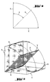
- the geometrical relationships of the sealing caps are intended to be based on the example of the sealing cap 8 will be explained, which is shown schematically in Figs. 4 and 5.
- a plane running essentially parallel to the axis of the hollow shaft provided with the reference symbol A.
- One running through the surface of the presser The plane has the reference symbol V.
- the plane A parallel to the axis symbolizes the End position of the open cover 8, while level E the cover 8 symbolizes in its closed end position.
- Due to its spatially curved Joint line is spanned by the flexure 9, a plane V, which is opposite to the Axis-parallel plane A and the plane E defined by the presser run inclined.
- the angle of inclination which the plane V spanned by the curved flexible joint 9 has of the axis-parallel plane A has the reference symbol ⁇ in FIG. 4.
- the angle of inclination ⁇ of the plane V range from approximately 30 ° to approximately 75 °.
- A is preferred Inclination angle ⁇ of about 45 °, at which the cover 8 with respect to occurring compressive and tensile stresses largely symmetrical relationships surrender.
- cover 7, 8 easier when closing or opening Reverse curvature, they are provided with predetermined bending points, which differ from the curved bending joint 9 to the free edge of each cover 7, 8 extend and are provided with reference number 12 in FIG. 1.
- the transition from the convex for concave curvature of a cover 7, 8 takes place when the Closure cover in an intermediate position, in which the closure cover 7, 8 den exposed to the highest tensile and compressive stresses.
- This liner of the Sealing cover 7, 8 corresponds exactly to that of the spatially curved bending joint 9 spanned plane V (Fig. 4 and 5) and represents an unstable position of the cover 7, 8.
- the design of the flexible joint according to the invention is not based on the described Embodiment of a fastening device for plate-shaped insulation elements limited, the opening in the press with two flap-like caps can be covered.
- the curvature of the flexible joint according to the invention can also can be used for fasteners with only one cover to ensure that Sealing lid in the open or in the closed state without further aids to be fixed in a defined and stable end position, which can only be achieved by applying a predeterminable minimum force is changeable.
- the fastening device exists at least partially made of plastic.
- the presser with hollow shaft and Sealing caps is with the usual mass production processes, for example in an injection molding process.
- the curved joint is preferably as Hinge joint designed.
Landscapes
- Engineering & Computer Science (AREA)
- Architecture (AREA)
- Structural Engineering (AREA)
- Civil Engineering (AREA)
- Physics & Mathematics (AREA)
- General Engineering & Computer Science (AREA)
- Acoustics & Sound (AREA)
- Electromagnetism (AREA)
- Mechanical Engineering (AREA)
- Connection Of Plates (AREA)
- Building Environments (AREA)
- Mounting, Exchange, And Manufacturing Of Dies (AREA)
- Insertion Pins And Rivets (AREA)
Abstract
Description
Claims (8)
- Befestigungsvorrichtung für plattenförmige Isolationselemente mit einem flachen Anpressteller (2) und einem davon abragenden Hohlschaft (3), der einen Hohlraum (4) umschliesst, der in einer Öffnung (6) im Anpressteller (2) mündet, welche durch wenigstens einen am Anpressteller (2) angelenkten, plattenartigen Verschlussdeckel (7, 8) verschliessbar ist, und mit in axialer Verlängerung des Hohlschafts (3) verlaufenden Verankerungsteilen (5), dadurch gekennzeichnet, dass der plattenartige Verschlussdeckel (7, 8) ein im wesentlichen linienförmiges Biegegelenk (9) aufweist, das in unmittelbarer Nachbarschaft zu der Öffnung (6) am Anpressteller (2) angeordnet und räumlich derart gekrümmt ist, dass es eine Ebene (V) aufspannt, die gegenüber einer vom flachen Anpressteller (2) definierten Ebene (E) und einer parallel zur Achse des Hohlschaftes (3) verlaufenden Ebene (A) geneigt verläuft.
- Befestigungsvorrichtung nach Anspruch 1, dadurch gekennzeichnet, dass die vom gekrümmten Biegegelenk (9) aufgespannte Ebene (V) gegenüber der Ebene (E) des Anpresstellers (2) um einen Winkel (α) in Richtung der achsparallelen Ebene (A) geneigt ist, der etwa 30° bis etwa 75°, vorzugsweise etwa 45° beträgt.
- Befestigungsvorrichtung nach Anspruch 1 oder 2, dadurch gekennzeichnet, dass der Anpressteller (2) einen die Öffnung (6) umrandenden, vertieften Bereich (10) aufweist, der zur Aufnahme des plattenförmigen Verschlussdeckels (7, 8) ausgebildet ist und wenigstens an der dem gekrümmten Biegegelenk (9) gegenüberliegende Seite der Öffnung (6) eine Anschlagschulter (11) bildet.
- Befestigungsvorrichtung nach Anspruch 3, dadurch gekennzeichnet, dass die Öffnung (6) im Anpressteller (2) entlang ihres gesamten Umfangs von einer im wesentlichen durchgehenden Anschlagschulter (11) berandet wird.
- Befestigungsvorrichtung nach einem der vorangehenden Ansprüche, dadurch gekennzeichnet, dass der Verschlussdeckel (7, 8) mit Sollbiegestellen (12) versehen ist, die sich vom gekrümmten Biegegelenk (9) zum freien Ende des Verschlussdeckels (7, 8) erstrecken.
- Befestigungsvorrichtung nach einem der vorangehenden Ansprüche, dadurch gekennzeichnet, dass das gekrümmte Biegegelenk (9) ein Folienscharnier ist.
- Befestigungsvorrichtung nach einem der vorangehenden Ansprüche, dadurch gekennzeichnet, dass zwei plattenförmige Verschlussdeckel (7, 8) vorgesehen sind, die an einander gegenüberliegenden Bereichen beidseits der Öffnung (6) am Anpressteller (2) angelenkt sind und sich jeweils von einem gekrümmten, linienförmigen Biegegelenk (9) in Richtung des gegenüberliegenden Verschlussdeckels erstrecken.
- Befestigungsvorrichtung nach Anspruch 7, dadurch gekennzeichnet, dass die Verschlussdeckel (7, 8) im zugeklappten Zustand die Öffnung (6) jeweils etwa zur Hälfte abdecken.
Applications Claiming Priority (2)
| Application Number | Priority Date | Filing Date | Title |
|---|---|---|---|
| DE19921151A DE19921151A1 (de) | 1999-05-07 | 1999-05-07 | Befestigungsvorrichtung für plattenförmige Isolationselemente |
| DE19921151 | 1999-05-07 |
Publications (3)
| Publication Number | Publication Date |
|---|---|
| EP1050690A2 true EP1050690A2 (de) | 2000-11-08 |
| EP1050690A3 EP1050690A3 (de) | 2002-04-17 |
| EP1050690B1 EP1050690B1 (de) | 2004-09-29 |
Family
ID=7907343
Family Applications (1)
| Application Number | Title | Priority Date | Filing Date |
|---|---|---|---|
| EP00810365A Expired - Lifetime EP1050690B1 (de) | 1999-05-07 | 2000-05-01 | Befestigungsvorrichtung für plattenförmige Isolationselemente |
Country Status (4)
| Country | Link |
|---|---|
| US (1) | US6234736B1 (de) |
| EP (1) | EP1050690B1 (de) |
| AT (1) | ATE278115T1 (de) |
| DE (2) | DE19921151A1 (de) |
Cited By (4)
| Publication number | Priority date | Publication date | Assignee | Title |
|---|---|---|---|---|
| WO2013122510A1 (ru) * | 2012-02-14 | 2013-08-22 | Prokhorov Igor Viktorovich | Дюбель для крепления теплоизолирующих плит |
| RU2501991C2 (ru) * | 2012-02-14 | 2013-12-20 | Игорь Викторович Прохоров | Дюбель для крепления теплоизолирующих плит |
| RU171773U1 (ru) * | 2016-12-29 | 2017-06-15 | Игорь Викторович Прохоров | Устройство для крепления теплоизоляции |
| US9879416B2 (en) | 2013-11-06 | 2018-01-30 | Owens Corning Intellectual Capital, Llc | Composite thermal isolating masonry tie fastener |
Families Citing this family (21)
| Publication number | Priority date | Publication date | Assignee | Title |
|---|---|---|---|---|
| US10640425B2 (en) | 1996-01-19 | 2020-05-05 | Romeo Ilarian Ciuperca | Method for predetermined temperature profile controlled concrete curing container and apparatus for same |
| US20060207204A1 (en) * | 2005-03-18 | 2006-09-21 | Bfs Diversified Products, Llc | Fastener, roofing system and method |
| US8555583B2 (en) | 2010-04-02 | 2013-10-15 | Romeo Ilarian Ciuperca | Reinforced insulated concrete form |
| US8555584B2 (en) | 2011-09-28 | 2013-10-15 | Romeo Ilarian Ciuperca | Precast concrete structures, precast tilt-up concrete structures and methods of making same |
| US8756890B2 (en) | 2011-09-28 | 2014-06-24 | Romeo Ilarian Ciuperca | Insulated concrete form and method of using same |
| EP2776374A4 (de) | 2011-11-11 | 2015-11-04 | Romeo Ilarian Ciuperca | Betonmischungszusammensetzung, mörtelmischungszusammensetzung und verfahren zur herstellung und abbindung von beton- oder mörtelobjekten und -strukturen |
| US8636941B1 (en) | 2012-09-25 | 2014-01-28 | Romeo Ilarian Ciuperca | Methods of making concrete runways, roads, highways and slabs on grade |
| US8877329B2 (en) | 2012-09-25 | 2014-11-04 | Romeo Ilarian Ciuperca | High performance, highly energy efficient precast composite insulated concrete panels |
| US8532815B1 (en) | 2012-09-25 | 2013-09-10 | Romeo Ilarian Ciuperca | Method for electronic temperature controlled curing of concrete and accelerating concrete maturity or equivalent age of concrete structures and objects |
| US9458637B2 (en) | 2012-09-25 | 2016-10-04 | Romeo Ilarian Ciuperca | Composite insulated plywood, insulated plywood concrete form and method of curing concrete using same |
| US8844227B1 (en) | 2013-03-15 | 2014-09-30 | Romeo Ilarian Ciuperca | High performance, reinforced insulated precast concrete and tilt-up concrete structures and methods of making same |
| US10065339B2 (en) | 2013-05-13 | 2018-09-04 | Romeo Ilarian Ciuperca | Removable composite insulated concrete form, insulated precast concrete table and method of accelerating concrete curing using same |
| CA2911409C (en) | 2013-05-13 | 2021-03-02 | Romeo Ilarian Ciuperca | Insulated concrete battery mold, insulated passive concrete curing system, accelerated concrete curing apparatus and method of using same |
| CA2923717A1 (en) * | 2013-09-09 | 2015-03-12 | Romeo Ilarian Ciuperca | Insulated concrete slip form and method of accelerating concrete curing using same |
| US9862118B2 (en) | 2013-09-09 | 2018-01-09 | Romeo Ilarian Ciuperca | Insulated flying table concrete form, electrically heated flying table concrete form and method of accelerating concrete curing using same |
| US8966845B1 (en) | 2014-03-28 | 2015-03-03 | Romeo Ilarian Ciuperca | Insulated reinforced foam sheathing, reinforced vapor permeable air barrier foam panel and method of making and using same |
| US9574341B2 (en) | 2014-09-09 | 2017-02-21 | Romeo Ilarian Ciuperca | Insulated reinforced foam sheathing, reinforced elastomeric vapor permeable air barrier foam panel and method of making and using same |
| US10280622B2 (en) | 2016-01-31 | 2019-05-07 | Romeo Ilarian Ciuperca | Self-annealing concrete forms and method of making and using same |
| FR3082543B1 (fr) * | 2018-06-19 | 2021-02-12 | Saint Gobain Isover | Dispositif d'entretoisement pour la fixation d'un parement |
| US11293477B2 (en) * | 2019-10-11 | 2022-04-05 | Jon Jay Goeders | Washer for securing spherical and cylindrical objects |
| US20230287678A1 (en) * | 2022-03-11 | 2023-09-14 | Certainteed Llc | Insulation standoffs and exterior insulation systems |
Citations (1)
| Publication number | Priority date | Publication date | Assignee | Title |
|---|---|---|---|---|
| US5118235A (en) | 1991-02-11 | 1992-06-02 | Illinois Tool Works Inc. | Washer with integral flap and fastening assembly combining fastener with such washer |
Family Cites Families (3)
| Publication number | Priority date | Publication date | Assignee | Title |
|---|---|---|---|---|
| DE3045986C2 (de) * | 1980-12-05 | 1985-04-04 | Adolf Böhl Schrauben- und Kunststoffwerk GmbH & Co, 5920 Bad Berleburg | Befestigungselement für die Befestigung von wärmeisolierenden Platten |
| DE4041819A1 (de) * | 1990-12-24 | 1992-06-25 | Hilti Ag | Befestigungselement fuer isolationsplatten |
| DE19619318A1 (de) * | 1996-05-14 | 1997-11-20 | Hilti Ag | Dämmstoffbefestigungselement |
-
1999
- 1999-05-07 DE DE19921151A patent/DE19921151A1/de not_active Withdrawn
-
2000
- 2000-05-01 EP EP00810365A patent/EP1050690B1/de not_active Expired - Lifetime
- 2000-05-01 AT AT00810365T patent/ATE278115T1/de active
- 2000-05-01 DE DE50007958T patent/DE50007958D1/de not_active Expired - Lifetime
- 2000-05-03 US US09/563,578 patent/US6234736B1/en not_active Expired - Lifetime
Patent Citations (1)
| Publication number | Priority date | Publication date | Assignee | Title |
|---|---|---|---|---|
| US5118235A (en) | 1991-02-11 | 1992-06-02 | Illinois Tool Works Inc. | Washer with integral flap and fastening assembly combining fastener with such washer |
Cited By (5)
| Publication number | Priority date | Publication date | Assignee | Title |
|---|---|---|---|---|
| WO2013122510A1 (ru) * | 2012-02-14 | 2013-08-22 | Prokhorov Igor Viktorovich | Дюбель для крепления теплоизолирующих плит |
| RU2501991C2 (ru) * | 2012-02-14 | 2013-12-20 | Игорь Викторович Прохоров | Дюбель для крепления теплоизолирующих плит |
| EA029236B1 (ru) * | 2012-02-14 | 2018-02-28 | Игорь Викторович Прохоров | Дюбель для крепления теплоизолирующих плит |
| US9879416B2 (en) | 2013-11-06 | 2018-01-30 | Owens Corning Intellectual Capital, Llc | Composite thermal isolating masonry tie fastener |
| RU171773U1 (ru) * | 2016-12-29 | 2017-06-15 | Игорь Викторович Прохоров | Устройство для крепления теплоизоляции |
Also Published As
| Publication number | Publication date |
|---|---|
| EP1050690B1 (de) | 2004-09-29 |
| ATE278115T1 (de) | 2004-10-15 |
| US6234736B1 (en) | 2001-05-22 |
| DE19921151A1 (de) | 2000-11-09 |
| EP1050690A3 (de) | 2002-04-17 |
| DE50007958D1 (de) | 2004-11-04 |
Similar Documents
| Publication | Publication Date | Title |
|---|---|---|
| EP1050690B1 (de) | Befestigungsvorrichtung für plattenförmige Isolationselemente | |
| DE3045986C2 (de) | Befestigungselement für die Befestigung von wärmeisolierenden Platten | |
| EP2815138B1 (de) | Schraube und damit hergestellte dünnblechverbindung | |
| DE3137836A1 (de) | Lastverteilende zwischenlegscheibe zur verwendung bei zusammendrueckbarem material | |
| EP0765979A1 (de) | Befestigungselement für die Befestigung von wärmeisolierenden Materialien | |
| DE69711740T2 (de) | Einschlagbefestigungselement für Beton | |
| DE3321623C2 (de) | Isolierplattendübel aus Kunststoff | |
| DE19651046A1 (de) | Dämmstoffhalter | |
| EP0504572A1 (de) | Befestigungselement für die Befestigung von wärmeisolierenden Platten | |
| EP1175567B1 (de) | Befestigungselement zum befestigen von isolationsbahnen oder-platten auf einem festen unterbau | |
| EP1048856A2 (de) | Befestigungselement zur Befestigung von Isolierelementen | |
| DE4444274C2 (de) | Kämpfer-Verbinder | |
| EP0034346B1 (de) | Befestigungssatz zum Befestigen von Verkleidungen, Leisten oder dergleichen Bauteilen an einer Wand mittels eines Klemmkopfdübels aus Kunststoff | |
| EP2053179B1 (de) | Dämmstofhalter | |
| EP3093412A1 (de) | Bewehrungsanschlusselement | |
| EP0807722A2 (de) | Dämmstoffbefestigungselement | |
| DE4320284A1 (de) | Dichtungsanordnung für den Einsatz bei mechanisch miteinander zu verbindenden Pfosten- und Rahmenelementen | |
| EP3176448B1 (de) | Verbindungselement | |
| DE102006042052B4 (de) | Isolierplattendübel | |
| DE19808927C1 (de) | Befestigungselement für die Befestigung von wärmeisolierenden Platten an einer Unterkonstruktion mit Montagekontrolle | |
| EP0845606A1 (de) | Befestigungselement | |
| DE20021397U1 (de) | Dübel | |
| EP0155484B1 (de) | Spreizdübel | |
| DE10119116B4 (de) | Dämmstoffdübel mit Verschlußscheibe | |
| EP0819807B1 (de) | Dämmstoffbefestigungselement |
Legal Events
| Date | Code | Title | Description |
|---|---|---|---|
| PUAI | Public reference made under article 153(3) epc to a published international application that has entered the european phase |
Free format text: ORIGINAL CODE: 0009012 |
|
| AK | Designated contracting states |
Kind code of ref document: A2 Designated state(s): AT CH DE FR LI Kind code of ref document: A2 Designated state(s): AT BE CH CY DE DK ES FI FR GB GR IE IT LI LU MC NL PT SE |
|
| AX | Request for extension of the european patent |
Free format text: AL;LT;LV;MK;RO;SI |
|
| PUAL | Search report despatched |
Free format text: ORIGINAL CODE: 0009013 |
|
| AK | Designated contracting states |
Kind code of ref document: A3 Designated state(s): AT BE CH CY DE DK ES FI FR GB GR IE IT LI LU MC NL PT SE |
|
| AX | Request for extension of the european patent |
Free format text: AL;LT;LV;MK;RO;SI |
|
| RIC1 | Information provided on ipc code assigned before grant |
Free format text: 7F 16B 13/04 A |
|
| 17P | Request for examination filed |
Effective date: 20021017 |
|
| AKX | Designation fees paid |
Free format text: AT CH DE FR LI |
|
| 17Q | First examination report despatched |
Effective date: 20030122 |
|
| GRAP | Despatch of communication of intention to grant a patent |
Free format text: ORIGINAL CODE: EPIDOSNIGR1 |
|
| GRAS | Grant fee paid |
Free format text: ORIGINAL CODE: EPIDOSNIGR3 |
|
| GRAA | (expected) grant |
Free format text: ORIGINAL CODE: 0009210 |
|
| AK | Designated contracting states |
Kind code of ref document: B1 Designated state(s): AT CH DE FR LI |
|
| REG | Reference to a national code |
Ref country code: CH Ref legal event code: EP |
|
| REG | Reference to a national code |
Ref country code: IE Ref legal event code: FG4D Free format text: GERMAN |
|
| REF | Corresponds to: |
Ref document number: 50007958 Country of ref document: DE Date of ref document: 20041104 Kind code of ref document: P |
|
| REG | Reference to a national code |
Ref country code: IE Ref legal event code: FD4D |
|
| PLBE | No opposition filed within time limit |
Free format text: ORIGINAL CODE: 0009261 |
|
| STAA | Information on the status of an ep patent application or granted ep patent |
Free format text: STATUS: NO OPPOSITION FILED WITHIN TIME LIMIT |
|
| ET | Fr: translation filed | ||
| 26N | No opposition filed |
Effective date: 20050630 |
|
| REG | Reference to a national code |
Ref country code: FR Ref legal event code: PLFP Year of fee payment: 17 |
|
| REG | Reference to a national code |
Ref country code: FR Ref legal event code: PLFP Year of fee payment: 18 |
|
| REG | Reference to a national code |
Ref country code: FR Ref legal event code: PLFP Year of fee payment: 19 |
|
| PGFP | Annual fee paid to national office [announced via postgrant information from national office to epo] |
Ref country code: DE Payment date: 20190521 Year of fee payment: 20 |
|
| PGFP | Annual fee paid to national office [announced via postgrant information from national office to epo] |
Ref country code: FR Payment date: 20190522 Year of fee payment: 20 |
|
| PGFP | Annual fee paid to national office [announced via postgrant information from national office to epo] |
Ref country code: CH Payment date: 20190521 Year of fee payment: 20 |
|
| PGFP | Annual fee paid to national office [announced via postgrant information from national office to epo] |
Ref country code: AT Payment date: 20190522 Year of fee payment: 20 |
|
| REG | Reference to a national code |
Ref country code: CH Ref legal event code: PL |
|
| REG | Reference to a national code |
Ref country code: DE Ref legal event code: R071 Ref document number: 50007958 Country of ref document: DE |
|
| REG | Reference to a national code |
Ref country code: AT Ref legal event code: MK07 Ref document number: 278115 Country of ref document: AT Kind code of ref document: T Effective date: 20200501 |