EP1050678B1 - Leitschaufel - Google Patents
Leitschaufel Download PDFInfo
- Publication number
- EP1050678B1 EP1050678B1 EP00303787A EP00303787A EP1050678B1 EP 1050678 B1 EP1050678 B1 EP 1050678B1 EP 00303787 A EP00303787 A EP 00303787A EP 00303787 A EP00303787 A EP 00303787A EP 1050678 B1 EP1050678 B1 EP 1050678B1
- Authority
- EP
- European Patent Office
- Prior art keywords
- exhaust
- nozzle
- vanes
- leading
- crown
- Prior art date
- Legal status (The legal status is an assumption and is not a legal conclusion. Google has not performed a legal analysis and makes no representation as to the accuracy of the status listed.)
- Expired - Lifetime
Links
Images

Classifications
-
- B—PERFORMING OPERATIONS; TRANSPORTING
- B64—AIRCRAFT; AVIATION; COSMONAUTICS
- B64D—EQUIPMENT FOR FITTING IN OR TO AIRCRAFT; FLIGHT SUITS; PARACHUTES; ARRANGEMENTS OR MOUNTING OF POWER PLANTS OR PROPULSION TRANSMISSIONS IN AIRCRAFT
- B64D33/00—Arrangements in aircraft of power plant parts or auxiliaries not otherwise provided for
- B64D33/04—Arrangements in aircraft of power plant parts or auxiliaries not otherwise provided for of exhaust outlets or jet pipes
-
- F—MECHANICAL ENGINEERING; LIGHTING; HEATING; WEAPONS; BLASTING
- F01—MACHINES OR ENGINES IN GENERAL; ENGINE PLANTS IN GENERAL; STEAM ENGINES
- F01D—NON-POSITIVE DISPLACEMENT MACHINES OR ENGINES, e.g. STEAM TURBINES
- F01D5/00—Blades; Blade-carrying members; Heating, heat-insulating, cooling or antivibration means on the blades or the members
- F01D5/12—Blades
- F01D5/14—Form or construction
- F01D5/141—Shape, i.e. outer, aerodynamic form
-
- F—MECHANICAL ENGINEERING; LIGHTING; HEATING; WEAPONS; BLASTING
- F05—INDEXING SCHEMES RELATING TO ENGINES OR PUMPS IN VARIOUS SUBCLASSES OF CLASSES F01-F04
- F05D—INDEXING SCHEME FOR ASPECTS RELATING TO NON-POSITIVE-DISPLACEMENT MACHINES OR ENGINES, GAS-TURBINES OR JET-PROPULSION PLANTS
- F05D2240/00—Components
- F05D2240/10—Stators
- F05D2240/12—Fluid guiding means, e.g. vanes
- F05D2240/128—Nozzles
-
- F—MECHANICAL ENGINEERING; LIGHTING; HEATING; WEAPONS; BLASTING
- F05—INDEXING SCHEMES RELATING TO ENGINES OR PUMPS IN VARIOUS SUBCLASSES OF CLASSES F01-F04
- F05D—INDEXING SCHEME FOR ASPECTS RELATING TO NON-POSITIVE-DISPLACEMENT MACHINES OR ENGINES, GAS-TURBINES OR JET-PROPULSION PLANTS
- F05D2250/00—Geometry
- F05D2250/70—Shape
- F05D2250/71—Shape curved
- F05D2250/711—Shape curved convex
-
- Y—GENERAL TAGGING OF NEW TECHNOLOGICAL DEVELOPMENTS; GENERAL TAGGING OF CROSS-SECTIONAL TECHNOLOGIES SPANNING OVER SEVERAL SECTIONS OF THE IPC; TECHNICAL SUBJECTS COVERED BY FORMER USPC CROSS-REFERENCE ART COLLECTIONS [XRACs] AND DIGESTS
- Y02—TECHNOLOGIES OR APPLICATIONS FOR MITIGATION OR ADAPTATION AGAINST CLIMATE CHANGE
- Y02T—CLIMATE CHANGE MITIGATION TECHNOLOGIES RELATED TO TRANSPORTATION
- Y02T50/00—Aeronautics or air transport
- Y02T50/60—Efficient propulsion technologies, e.g. for aircraft
Landscapes
- Engineering & Computer Science (AREA)
- Mechanical Engineering (AREA)
- Physics & Mathematics (AREA)
- Fluid Mechanics (AREA)
- General Engineering & Computer Science (AREA)
- Chemical & Material Sciences (AREA)
- Combustion & Propulsion (AREA)
- Aviation & Aerospace Engineering (AREA)
- Control Of Turbines (AREA)
- Turbine Rotor Nozzle Sealing (AREA)
- Supercharger (AREA)
- Exhaust Silencers (AREA)
Claims (13)
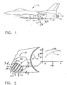
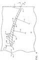
- Kaskadenausstoßdüse (20), mit einem Kanal (22) mit einer Vielzahl von Lamellen (24), die so zueinander beabstandet sind, dass entsprechende Düsenkanäle (26) zum Abführen des Abgasstroms gebildet werden, wobei jede der Lamellen (24) eine sich zwischen einer Eintrittskante und einer Austrittskante (32, 34) erstreckende Oberseite und Unterseite (28, 30) aufweist und durch einen nach der Eintrittskante entlang der Oberseite angeordneten Rücken (36) gekennzeichnet ist, und wobei jeder der Düsenkanäle (26) einen vorderen Teil (38), der von den Eintrittskanten (32) zu einer eine Austrittskante (34) und einen Rücken (36) benachbarter Lamellen überbrückenden effektiven Verengung (40) reicht, sowie einen hinteren Teil (42) aufweist, der von der Verengung (40) zu den Austrittskanten (34) reicht; und wobei der Abgasstrom in dem vorderen Teil (38) subsonisch gedreht, in der Verengung (40) sonisch gedrosselt und im hinteren Teil (42) einer supersonischen Diffusorwirkung unterworfen wird.
- Ausstoßdüse nach Anspruch 1, dadurch gekennzeichnet, dass jede Düsenlamelle zwischen der Eintrittskante (32) und dem Rücken (36) eine flache Nase (48) umfasst.
- Ausstoßdüse nach Anspruch 1, dadurch gekennzeichnet, dass jede Düsenlamelle zwischen dem Rücken (36) und der Austrittskante (34) einen bogenförmigen Schwanz (50) umfasst.
- Ausstoßdüse nach Anspruch 3, dadurch gekennzeichnet, dass jeder Düsenlamellenschwanz (50) einen einzigen Außenradius (D) der Krümmung zwischen dem Rücken (36) und der Austrittskante (34) entlang der Oberseite (28) sowie einen einzigen Innenradius (E) der Krümmung entlang der Innenseite (34) aufweist, wobei der Innenradius kleiner als der Außenradius ist.
- Ausstoßdüse nach Anspruch 1, dadurch gekennzeichnet, dass die Eintritts- und Austrittskante (32, 34) jeder Düsenlamelle konvex sind.
- Ausstoßdüse nach Anspruch 1, dadurch gekennzeichnet, dass die Eintrittskante (32) jeder Düsenlamelle sich in einem ebenen Bereich (52) mit der Unterseite (30) vereinigt.
- Ausstoßdüse nach Anspruch 1, dadurch gekennzeichnet, dass jede Düsenlamelle ferner eine Weite (S) umfasst, und dass die Oberseite und Unterseite (28, 30) ein im Wesentlichen konstantes Profil aufweisen.
- Ausstoßdüse nach Anspruch 1, dadurch gekennzeichnet, dass jede Düsenlamelle zwischen der Eintrittskante und der Austrittskante eine Sehne (C) aufweist, wobei der Rücken (36) nach etwa 20 Prozent der Sehnenlänge im Abstand zur Eintrittskante angeordnet ist.
- Ausstoßdüse nach Anspruch 1, dadurch gekennzeichnet, dass die Abgasstromdrehung mehrheitlich in der Nähe der Lamelleneintrittskanten (32) erfolgt, um das Flächenverhältnis der Kanäle (26) stromab zu verringern und den Schubwirkungsgrad bei einem niedrigeren Druckverhältnis entlang der Lamellen zu erhöhen.
- Ausstoßdüse nach Anspruch 9, dadurch gekennzeichnet, dass der Abgasstrom um 22,5 Grad zwischen den Eintrittskanten und den Austrittskanten (32, 34) bei einem Schubwirkungsgrad von 98,5 Prozent und einem Druckverhältnis von etwa 2,06 entlang der Lamellen gedreht wird.
- Ausstoßdüse nach Anspruch 10, dadurch gekennzeichnet, dass die Lamellen (24) eine Festigkeit von weniger als etwa 1,0 aufweisen.
- Verfahren zum Drehen des Abgasstroms durch eine Vielzahl von zwischen entsprechenden Kaskadenlamellen (24) gebildeten Düsenkanälen (26), wobei jede der Lamellen eine sich zwischen einer Eintrittskante und einer Austrittskante (32, 34) erstreckende Oberseite und Unterseite (28, 30) sowie einen nach der Eintrittskante entlang der Oberseite angeordneten Rücken (36) aufweist, wobei jeder der Düsenkanäle (26) einen vorderen Teil (38), der von den Eintrittskanten (32) zu einer eine Austrittskante und einen Rücken benachbarter Lamellen überbrückenden effektiven Verengung (40) reicht, sowie einen hinteren Teil (42) aufweist, der von der Verengung (40) zu den Austrittskanten (34) reicht; wobei der Abgasstrom in der Nähe der Eintrittskanten (32) der Lamellen subsonisch gedreht wird und der gedrehte Abgasstrom stromab von dort supersonisch einer Diffusionswirkung unterworfen wird und wobei der Abgasstrom an einer Verengung sonisch gedrosselt wird.
- Verfahren nach Anspruch 12, dadurch gekennzeichnet, dass der Abgasstrom um 22,5 Grad zwischen den Eintrittskanten und den Austrittskanten bei einem Schubwirkungsgrad von 98,5 Prozent und einem Druckverhältnis von etwa 2,06 entlang der Lamellen gedreht wird.
Applications Claiming Priority (2)
| Application Number | Priority Date | Filing Date | Title |
|---|---|---|---|
| US09/305,648 US6260794B1 (en) | 1999-05-05 | 1999-05-05 | Dolphin cascade vane |
| US305648 | 1999-05-05 |
Publications (3)
| Publication Number | Publication Date |
|---|---|
| EP1050678A2 EP1050678A2 (de) | 2000-11-08 |
| EP1050678A3 EP1050678A3 (de) | 2003-05-21 |
| EP1050678B1 true EP1050678B1 (de) | 2005-12-14 |
Family
ID=23181708
Family Applications (1)
| Application Number | Title | Priority Date | Filing Date |
|---|---|---|---|
| EP00303787A Expired - Lifetime EP1050678B1 (de) | 1999-05-05 | 2000-05-05 | Leitschaufel |
Country Status (5)
| Country | Link |
|---|---|
| US (1) | US6260794B1 (de) |
| EP (1) | EP1050678B1 (de) |
| JP (1) | JP4531926B2 (de) |
| DE (1) | DE60024711T2 (de) |
| ES (1) | ES2253182T3 (de) |
Families Citing this family (21)
| Publication number | Priority date | Publication date | Assignee | Title |
|---|---|---|---|---|
| CN100390397C (zh) * | 2005-04-30 | 2008-05-28 | 张鸿元 | 空气压缩航空发动机 |
| US7836681B2 (en) * | 2006-06-13 | 2010-11-23 | Rolls-Royce Corporation | Mechanism for a vectoring exhaust nozzle |
| US8973374B2 (en) | 2007-09-06 | 2015-03-10 | United Technologies Corporation | Blades in a turbine section of a gas turbine engine |
| US8468797B2 (en) | 2007-09-06 | 2013-06-25 | United Technologies Corporation | Gas turbine engine systems and related methods involving vane-blade count ratios greater than unity |
| US7984607B2 (en) * | 2007-09-06 | 2011-07-26 | United Technologies Corp. | Gas turbine engine systems and related methods involving vane-blade count ratios greater than unity |
| FR2953808B1 (fr) * | 2009-12-11 | 2016-09-09 | li jing Chen | Un avion dont le rapport poussee-poids est inferieur a 1 arrive a decoller et atterrir de facon verticale |
| US8714913B2 (en) | 2012-01-31 | 2014-05-06 | United Technologies Corporation | Low noise compressor rotor for geared turbofan engine |
| US8246292B1 (en) | 2012-01-31 | 2012-08-21 | United Technologies Corporation | Low noise turbine for geared turbofan engine |
| US8632301B2 (en) | 2012-01-31 | 2014-01-21 | United Technologies Corporation | Low noise compressor rotor for geared turbofan engine |
| US9624834B2 (en) | 2012-09-28 | 2017-04-18 | United Technologies Corporation | Low noise compressor rotor for geared turbofan engine |
| US8834099B1 (en) | 2012-09-28 | 2014-09-16 | United Technoloiies Corporation | Low noise compressor rotor for geared turbofan engine |
| US20160138474A1 (en) | 2012-09-28 | 2016-05-19 | United Technologies Corporation | Low noise compressor rotor for geared turbofan engine |
| US11719161B2 (en) | 2013-03-14 | 2023-08-08 | Raytheon Technologies Corporation | Low noise turbine for geared gas turbine engine |
| US10605172B2 (en) | 2013-03-14 | 2020-03-31 | United Technologies Corporation | Low noise turbine for geared gas turbine engine |
| DE102014200644B4 (de) * | 2014-01-16 | 2017-03-02 | MTU Aero Engines AG | Strangprofil und Verfahren zur Herstellung einer Schaufel eines Nachleitrads, Schaufel eines Nachleitrads, Nachleitrad und Turbomaschine mit solch einem Nachleitrad |
| US9869190B2 (en) | 2014-05-30 | 2018-01-16 | General Electric Company | Variable-pitch rotor with remote counterweights |
| US10072510B2 (en) | 2014-11-21 | 2018-09-11 | General Electric Company | Variable pitch fan for gas turbine engine and method of assembling the same |
| US10100653B2 (en) | 2015-10-08 | 2018-10-16 | General Electric Company | Variable pitch fan blade retention system |
| EP3418507A1 (de) * | 2017-06-19 | 2018-12-26 | General Electric Company Polska Sp. Z o.o | Abgasanordnung mit wirbelgenerator |
| US11674435B2 (en) | 2021-06-29 | 2023-06-13 | General Electric Company | Levered counterweight feathering system |
| US11795964B2 (en) | 2021-07-16 | 2023-10-24 | General Electric Company | Levered counterweight feathering system |
Family Cites Families (16)
| Publication number | Priority date | Publication date | Assignee | Title |
|---|---|---|---|---|
| US3087303A (en) * | 1960-03-29 | 1963-04-30 | Northrop Corp | Jet propelled aircraft with jet deflecting means |
| GB980337A (en) | 1962-05-08 | 1965-01-13 | Power Jets Res & Dev Ltd | Improvements in or relating to a rotor for a compressor turbine or like bladed fluidflow machine |
| US3174709A (en) * | 1962-11-29 | 1965-03-23 | Gen Electric | Vectorable thrust mechanism |
| US3248877A (en) * | 1963-09-18 | 1966-05-03 | Gen Electric | Thrust deflector |
| US3314647A (en) * | 1964-12-16 | 1967-04-18 | Vladimir H Pavlecka | High energy conversion turbines |
| US3779010A (en) | 1972-08-17 | 1973-12-18 | Gen Electric | Combined thrust reversing and throat varying mechanism for a gas turbine engine |
| US4063851A (en) | 1975-12-22 | 1977-12-20 | United Technologies Corporation | Coolable turbine airfoil |
| US4463903A (en) | 1982-05-10 | 1984-08-07 | Nightingale Douglas J | Turbomachine ejector nozzle |
| US4587803A (en) | 1983-08-15 | 1986-05-13 | Rolls-Royce Inc. | Valve for diverting fluid flows in turbomachines |
| DE3811616C1 (de) * | 1988-04-07 | 1989-07-27 | Messerschmitt-Boelkow-Blohm Gmbh, 8012 Ottobrunn, De | |
| US5062588A (en) * | 1989-02-08 | 1991-11-05 | Boeing Of Canada Ltd. | Segmented rotatable nozzles |
| US5035578A (en) * | 1989-10-16 | 1991-07-30 | Westinghouse Electric Corp. | Blading for reaction turbine blade row |
| GB2276131B (en) * | 1993-03-13 | 1996-07-31 | Rolls Royce Plc | Variable camber vane |
| US5352092A (en) | 1993-11-24 | 1994-10-04 | Westinghouse Electric Corporation | Light weight steam turbine blade |
| US5779169A (en) * | 1995-12-15 | 1998-07-14 | The Boeing Company | Aircraft engine inlet hot gas and foreign object ingestion reduction and pitch control system |
| EP0934455B1 (de) * | 1996-10-28 | 2005-04-06 | Siemens Westinghouse Power Corporation | Turbomaschinenschaufel |
-
1999
- 1999-05-05 US US09/305,648 patent/US6260794B1/en not_active Expired - Lifetime
-
2000
- 2000-05-02 JP JP2000133927A patent/JP4531926B2/ja not_active Expired - Lifetime
- 2000-05-05 DE DE60024711T patent/DE60024711T2/de not_active Expired - Lifetime
- 2000-05-05 EP EP00303787A patent/EP1050678B1/de not_active Expired - Lifetime
- 2000-05-05 ES ES00303787T patent/ES2253182T3/es not_active Expired - Lifetime
Also Published As
| Publication number | Publication date |
|---|---|
| ES2253182T3 (es) | 2006-06-01 |
| JP2000356167A (ja) | 2000-12-26 |
| EP1050678A2 (de) | 2000-11-08 |
| EP1050678A3 (de) | 2003-05-21 |
| US6260794B1 (en) | 2001-07-17 |
| DE60024711D1 (de) | 2006-01-19 |
| JP4531926B2 (ja) | 2010-08-25 |
| DE60024711T2 (de) | 2006-08-24 |
Similar Documents
| Publication | Publication Date | Title |
|---|---|---|
| EP1050678B1 (de) | Leitschaufel | |
| CA2491619C (en) | Bifurcated outlet guide vanes | |
| EP1191214B1 (de) | Schubdüse mit Stummel-Schaufeln | |
| US6312219B1 (en) | Narrow waist vane | |
| US7549839B2 (en) | Variable geometry inlet guide vane | |
| US6532729B2 (en) | Shelf truncated chevron exhaust nozzle for reduction of exhaust noise and infrared (IR) signature | |
| EP2815096B1 (de) | Gasturbinenmotorkomponente mit konvergierendem/divergierendem kühlkanal | |
| EP2815103B1 (de) | Wand eines bauteils eines gasturbinentriebwerks und zugehöriger bauteil eines gasturbinentriebwerks | |
| US9242721B2 (en) | Aircraft propulsion system and a method of controlling the same | |
| EP1995441B1 (de) | Abgasdüse eines gasturbinentriebwerks | |
| US9410435B2 (en) | Gas turbine engine component with diffusive cooling hole | |
| US4012165A (en) | Fan structure | |
| JPH0678735B2 (ja) | ナセル構造体 | |
| JPH10502150A (ja) | 回転機械の圧縮領域のための流れ配向アッセンブリ | |
| GB2431697A (en) | Fan blade having maximum forward sweep at tip | |
| EP2971550B1 (de) | Schaufellüfterummantelung mit bereichsregelung | |
| EP1113162B1 (de) | Ein- und Auslasskanäle für ein Triebwerk mit zwei Bläsern | |
| AU2006246449A1 (en) | Vectorable nozzle with pivotable triangular panels | |
| EP3940212B1 (de) | Vorrichtungen und verfahren zur führung von zapfluft in einem turbofantriebwerk | |
| US20170298868A9 (en) | Gas turbine engine nozzle including housing having scalloped root regions | |
| EP3124779B1 (de) | Bypasskanalverkleidung für turbofan-triebwerk mit niedrigem nebenstromverhältnis und turbofan-triebwerk damit | |
| EP0560453A1 (de) | Turbostrahltriebwerk mit Überschallverdichter |
Legal Events
| Date | Code | Title | Description |
|---|---|---|---|
| PUAI | Public reference made under article 153(3) epc to a published international application that has entered the european phase |
Free format text: ORIGINAL CODE: 0009012 |
|
| AK | Designated contracting states |
Kind code of ref document: A2 Designated state(s): AT BE CH CY DE DK ES FI FR GB GR IE IT LI LU MC NL PT SE |
|
| AX | Request for extension of the european patent |
Free format text: AL;LT;LV;MK;RO;SI |
|
| PUAL | Search report despatched |
Free format text: ORIGINAL CODE: 0009013 |
|
| AK | Designated contracting states |
Designated state(s): AT BE CH CY DE DK ES FI FR GB GR IE IT LI LU MC NL PT SE |
|
| AX | Request for extension of the european patent |
Extension state: AL LT LV MK RO SI |
|
| RIC1 | Information provided on ipc code assigned before grant |
Ipc: 7F 02K 1/00 A Ipc: 7B 64D 33/04 B Ipc: 7F 01D 9/04 B Ipc: 7F 01D 25/30 B Ipc: 7F 01D 5/14 B |
|
| 17P | Request for examination filed |
Effective date: 20031121 |
|
| AKX | Designation fees paid |
Designated state(s): DE ES FR GB IT |
|
| 17Q | First examination report despatched |
Effective date: 20040326 |
|
| GRAP | Despatch of communication of intention to grant a patent |
Free format text: ORIGINAL CODE: EPIDOSNIGR1 |
|
| GRAS | Grant fee paid |
Free format text: ORIGINAL CODE: EPIDOSNIGR3 |
|
| GRAA | (expected) grant |
Free format text: ORIGINAL CODE: 0009210 |
|
| AK | Designated contracting states |
Kind code of ref document: B1 Designated state(s): DE ES FR GB IT |
|
| REG | Reference to a national code |
Ref country code: GB Ref legal event code: FG4D |
|
| REF | Corresponds to: |
Ref document number: 60024711 Country of ref document: DE Date of ref document: 20060119 Kind code of ref document: P |
|
| PGFP | Annual fee paid to national office [announced via postgrant information from national office to epo] |
Ref country code: ES Payment date: 20060526 Year of fee payment: 7 |
|
| REG | Reference to a national code |
Ref country code: ES Ref legal event code: FG2A Ref document number: 2253182 Country of ref document: ES Kind code of ref document: T3 |
|
| ET | Fr: translation filed | ||
| PLBE | No opposition filed within time limit |
Free format text: ORIGINAL CODE: 0009261 |
|
| STAA | Information on the status of an ep patent application or granted ep patent |
Free format text: STATUS: NO OPPOSITION FILED WITHIN TIME LIMIT |
|
| 26N | No opposition filed |
Effective date: 20060915 |
|
| REG | Reference to a national code |
Ref country code: ES Ref legal event code: FD2A Effective date: 20070507 |
|
| PG25 | Lapsed in a contracting state [announced via postgrant information from national office to epo] |
Ref country code: ES Free format text: LAPSE BECAUSE OF NON-PAYMENT OF DUE FEES Effective date: 20070507 |
|
| REG | Reference to a national code |
Ref country code: FR Ref legal event code: PLFP Year of fee payment: 17 |
|
| PGFP | Annual fee paid to national office [announced via postgrant information from national office to epo] |
Ref country code: GB Payment date: 20160527 Year of fee payment: 17 Ref country code: DE Payment date: 20160527 Year of fee payment: 17 |
|
| PGFP | Annual fee paid to national office [announced via postgrant information from national office to epo] |
Ref country code: FR Payment date: 20160530 Year of fee payment: 17 Ref country code: IT Payment date: 20160520 Year of fee payment: 17 |
|
| REG | Reference to a national code |
Ref country code: DE Ref legal event code: R119 Ref document number: 60024711 Country of ref document: DE |
|
| GBPC | Gb: european patent ceased through non-payment of renewal fee |
Effective date: 20170505 |
|
| REG | Reference to a national code |
Ref country code: FR Ref legal event code: ST Effective date: 20180131 |
|
| PG25 | Lapsed in a contracting state [announced via postgrant information from national office to epo] |
Ref country code: GB Free format text: LAPSE BECAUSE OF NON-PAYMENT OF DUE FEES Effective date: 20170505 Ref country code: DE Free format text: LAPSE BECAUSE OF NON-PAYMENT OF DUE FEES Effective date: 20171201 |
|
| PG25 | Lapsed in a contracting state [announced via postgrant information from national office to epo] |
Ref country code: IT Free format text: LAPSE BECAUSE OF NON-PAYMENT OF DUE FEES Effective date: 20170505 Ref country code: FR Free format text: LAPSE BECAUSE OF NON-PAYMENT OF DUE FEES Effective date: 20170531 |