EP1050661A2 - Improvements relating to subsea drilling of boreholes - Google Patents
Improvements relating to subsea drilling of boreholes Download PDFInfo
- Publication number
- EP1050661A2 EP1050661A2 EP00303819A EP00303819A EP1050661A2 EP 1050661 A2 EP1050661 A2 EP 1050661A2 EP 00303819 A EP00303819 A EP 00303819A EP 00303819 A EP00303819 A EP 00303819A EP 1050661 A2 EP1050661 A2 EP 1050661A2
- Authority
- EP
- European Patent Office
- Prior art keywords
- casing
- string
- casing string
- borehole
- annulus
- Prior art date
- Legal status (The legal status is an assumption and is not a legal conclusion. Google has not performed a legal analysis and makes no representation as to the accuracy of the status listed.)
- Granted
Links
Images


Classifications
-
- E—FIXED CONSTRUCTIONS
- E21—EARTH OR ROCK DRILLING; MINING
- E21B—EARTH OR ROCK DRILLING; OBTAINING OIL, GAS, WATER, SOLUBLE OR MELTABLE MATERIALS OR A SLURRY OF MINERALS FROM WELLS
- E21B7/00—Special methods or apparatus for drilling
- E21B7/12—Underwater drilling
Definitions
- the present invention relates to improved methods and apparatus for use in the drilling of subsea boreholes, particularly for the recovery of hydrocarbon products from subsea geological formations.
- This invention is most directly applicable to the solution of particular problems encountered in the drilling of boreholes in extremely deep water.
- An example of such operations is the drilling of boreholes in the Gulf of Mexico on the downslope of the continental shelf, in water depths of the order of 6000 to 7000 feet (1830 to 2130 metres), where the hydrocarbon-bearing formation may be a further 10,000 feet (3050 metres) beneath the seabed.
- the seabed often includes a top layer, usually of the order of 300 to 400 feet (90 to 120 metres) deep, of unconsolidated, mud-like material, followed by a layer of unconsolidated sedimentary rock, before consolidated geologic formation is reached.
- the invention relates to the particular problem of forming and casing the initial sections of a subsea borehole through layers of unconsolidated formation, where the depth of the unconsolidated formations is small compared to the depth of water in which the operation is to be performed.
- it is necessary first of all to drill and stabilise initial borehole sections through the unconsolidated layers.
- first borehole section through the first layer of mud-like material using fluid jetting techniques, with the required casing being lowered closely behind the jetting tool so as to stabilise the first borehole section as it is formed.
- This in itself is a simple form of "casing while drilling", but does not utilise a rotating drill-bit.
- the depth of the water compared with the required length of casing is such that the complete casing string can be pre-assembled and hung-off from the drilling vessel with the jetting tool string extending through the casing, before lowering the casing and jetting string to the seabed.
- the second section is drilled through the second layer, containing zones of overpressured water, typically using a 24 inch (60.96 cm) bit, and into the underlying formation, to accommodate 20 inch casing.
- This second borehole section may be of the order of 3000 feet (915 meters) in depth.
- the second borehole would be drilled in its entirety before withdrawing the drill string and running the casing string. If the borehole penetrates a zone of overpressured water, the resulting "shallow water flow" from the overpressured zone into the borehole will destroy or render useless the borehole before the casing can be run.
- One object of the present invention is therefore to mitigate the above problems by making use of the concept of casing-while-drilling in order to produce a stable, cased borehole through such unconsolidated sedimentary formations containing over-pressured seawater.
- a method of forming a subsea borehole from a drilling vessel in a body of water of known depth comprising securing a casing string to a drill string and running said strings, thereby excavating a section of the borehole in a typically unconsolidated formation while isolating the annulus between the casing string and the borehole section from fluid circulation and creating a hydrostatic pressure in the annulus adapted to balance any over pressurised water in the formation.
- the method may further comprise the prior steps of:
- the annulus is isolated from fluid circulation by means of sealing means provided on the outside of the casing string.
- Sufficient hydrostatic pressure may be created in the annulus by pumping a suitable gel into the annulus above the sealing means.
- the gel might typically comprise of a mixed metal hydroxide or mixed metal silicate base.
- the gel is pumped into the annulus during excavation of the said borehole section.
- the first borehole section is formed by means of fluid jetting tool, said first casing being run simultaneously with said fluid jetting tool.
- the said drill string is made up with a drill bit at its lowermost end and with a centraliser assembly incorporated therein above said drill bit.
- said casing string is made up with at least a first port collar incorporated therein at a distance from the uppermost end of the casing string which is greater than the length of said first casing.
- said annular sealing means comprises at least one cup seal element.
- said sealing means comprises a plurality of cup seal elements spaced along the length of the casing string.
- a casing string having a plurality of sealing means spaced on the outer surface thereof, and further having attached thereto a feed line for the supply of gel into the annulus between the casing string and the second borehole section when the string is run.
- the casing string is adapted for attachment to a drill string.
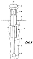
- a 36 inch casing string 10 and jetting string 30 are suspended from a running tool 50 via a housing 18.
- the overall arrangement of the 36 inch casing string 10 may include a centraliser joint (not shown) and standard 40 foot (12.19 metre) joints of 36 inch casing.
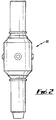
- a centraliser such as is illustrated in Figure 2 may also be provided on the jetting string 30 in order to maintain it in a correct orientation within the borehole.
- the equipment shown in Figure 1 may be used in the initial stages of excavating a borehole in unconsolidated layers near the seabed.
- the next stage of the operation is to excavate a second borehole section while simultaneously running a 20 inch casing into a second borehole section.
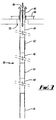
- This requires a 20 inch casing string as illustrated in Figure 3 and a suitable drill string as shown in Figure 4.
- the 20 inch casing string 56 comprises a shoe joint 58 at the lowermost end of the casing string, standard joints of 20 inch casing 60, and one or more port collars for use during the cementing of the 20 inch casing.
- the present invention involves the use of a fluid seal in the annulus between the 20 inch casing and the adjacent borehole section. This seal must be maintained while the 20 inch casing is being run into the borehole.
- the seal is provided on the outer surface of the 20 inch casing string as shown in Figures 5 and 6 and includes a plurality of cup seals 20 arranged in series. In this example, the seals 20 are retained in position by removable collars 26. This arrangement facilitates the removal of the seals 20 for replacement, repair or refurbishment.
- the cup seals 20 are designed to hold back the fluid pressure generated by the shallow salt water flows which are expected to be encountered in use of the invention. It will be understood that the number of seals 20, and, if necessary, the length of the seal joint body 24, may be varied to suit the parameters of a particular operation.
- the casing string 56 further includes a housing 66.
- the casing string 56 is made up to its complete length and hung off from the drilling vessel.
- the string 56 is initially hung off from a wellhead support frame 68 installed in the moonpool 70 of the drilling vessel.
- the shoe joint 58 is a heavy wall casing joint which serves to ensure that the 20 inch casing enters the 36 inch seal joint 14 cleanly and without damaging the seals 20 on the second casing string.
- the 20 inch drill string 72 includes a bottom hole assembly (BHA) comprising, from the bottom up:
- the drill string 72 is connected to the casing string, in use, by a wellhead running tool 88 (Fig. 5). Minor modification of a standard wellhead running tool is desirable for the purposes of the 20 inch string of the present invention, to provide an adequate flow-by area for the fluid and debris returns from the drilling operation.
- a feed line or top-up line 81 attached to the outside of the 20 inch casing string is a feed line or top-up line 81 adapted to supply gel into the annulus 83 between the casing and the borehole wall 89.
- the introduction of the gel into the annulus serves to provide a hydrostatic pressure that counters the over pressure of the water in the unconsolidated formations. Accordingly, the entire annulus 83 may be maintained at a pressure that balances or overbalances the overpressured fluid in the unconsolidated layers, with the exception of an approximate 2 to 3 foot gap directly above the bit face on the drill string.
- the swab cups 20 may allow some leakage of the gel and this should not be detrimental to the overall working of the invention in preventing the break down of the integrity of the bore hole.
- the combination of the gel and cups 20 substantially prevents the flow of well fluid in the annulus, mitigating erosion of the relatively weak formation. It is similarly possible to allow for low or controlled flow levels for the washing of the borehole prior to cementing or for other specific operations.
- the size of the annulus can be manipulated through the choice of different sized inner pipes, or with the use of fillers, such as buoyancy foams or the like.
- the running procedure for the 20 inch casing and drill string is as follows:
- the 20 inch casing 56 may be cemented in place in the borehole.
- the invention therefore provides methods and apparatus enabling a borehole to be established through unconsolidated formations which are liable to shallow salt water flow problems.
- casing while drilling is made possible by the fact that the water depth is greater than the required length of 20 inch casing (typically 6000 feet (1830 metres) water depth, compared with the 3000 feet (915 metre) length of the casing string).
- This allows the entire casing string to be assembled and hung off from the drilling vessel.
- the drill string can then be run through the pre-assembled casing.
- the casing string is then hung off from the drill string and detached from the drilling vessel, and can be lowered to the seabed along with the drill string, so that the casing follows closely behind the drill bit as drilling progresses. Accordingly, the borehole is protected by the casing against damage by shallow water flows released during the drilling operation.
Landscapes
- Life Sciences & Earth Sciences (AREA)
- Engineering & Computer Science (AREA)
- Geology (AREA)
- Mining & Mineral Resources (AREA)
- Physics & Mathematics (AREA)
- Environmental & Geological Engineering (AREA)
- Fluid Mechanics (AREA)
- General Life Sciences & Earth Sciences (AREA)
- Geochemistry & Mineralogy (AREA)
- Earth Drilling (AREA)
- Drilling And Boring (AREA)
Abstract
Description
- make up the
casing string 10 andjetting string 30 withjetting tool 32, - run the
jetting tool 32 through thecasing string 10, - make up the
housing 18 and runningtool 50 and pick up the 36 inch string and run to themudline 52 - operate the
jetting tool 32 to excavate thefirst borehole section 54 until thehousing 18 lands off in a template (not shown) previously installed at the borehole location (as is well known in the art) or until thehousing 18 is at a predetermined height above themudline 52, - continue circulation of jetting fluid through the
jetting
tool 32 until theborehole 54 has been cleared of debris, - discontinue circulation of jetting fluid, disconnect
the running
tool 50 from thehousing 18 and pull out the jettingstring 30 back to the drilling vessel.
Accordingly, the
- Make up and hang-off the 20
inch casing string 56 including the top upline 81; - make up the drill string with a BHA as described
above into the interior of the
casing string 56, - connect the drill string to the casing string, and
run the entire casing/drill string assembly on drill
pipe connected to the running
tool 88 to just above the mudline, - lower the assembly slowly to enter the previously
installed 36
inch housing 18, - establish circulation of drilling fluid through the
drill string and run in slowly until the
bit 74 and under-reamer 76 have exited the 36 inch shoe, - drill ahead to target depth while feeding the annulus with gel, and finally
- withdraw the drill string back to surface.
Claims (13)
- A method of forming a subsea borehole from a drilling vessel in a body of water of known depth, comprising securing a casing string to a drill string and running said strings, thereby excavating a section of the borehole in a typically unconsolidated formation while isolating the annulus between the casing string and the borehole section from fluid circulation and creating a hydrostatic pressure in the annulus adapted to balance any over pressurised water in the formation.
- A method as claimed in Claim 1 further comprising the prior steps of:forming a first borehole section lined with a first casing having a first diameter;making up the drill string and casing string with a second casing having a second diameter which is less than said first diameter, said casing string having an overall length less than the depth of the body of water, and hanging said casing string off from the drilling vessel;running said drill string through the interior of said casing string, securing said casing string to said drill string and disconnecting said casing string from said drilling vessel; andrunning said casing string and drill string together into the first borehole section.
- A method as claimed in Claim 1 or Claim 2 wherein the annulus is isolated from fluid circulation by means of a sealing means provided on the outside of the casing string.
- A method as claimed in Claim 3 wherein the balancing hydrostatic pressure is created in the annulus by pumping a suitable gel into the annulus above the sealing means.
- A method as claimed in Claim 4, wherein the gel comprises of a mixed metal hydroxide or mixed metal silicate base.
- A method as claimed in Claim 4 or Claim 5, wherein the gel is pumped into the annulus during excavation of the said borehole section.
- A method as claimed in any one of Claims 2 to 6, wherein the first borehole section is formed by means of a fluid jetting tool, said first casing being run simultaneously with said fluid jetting tool.
- A method as claimed in any one of the preceding Claims wherein the drill string is made up with a drill bit at its lowermost end and with a centraliser assembly incorporated therein above said drill bit.
- A method as claimed in any one of the preceding Claims, wherein the casing string is made up with at least a first port collar incorporated therein at a distance from the uppermost end of the casing string which is greater than the length of said first casing.
- A method as claimed in any one of Claims 3 to 9, wherein the annular sealing means comprises at least one cup seal element.
- A method as claimed in any one of Claims 3 to 10, wherein said sealing means comprises a plurality of cup seal elements spaced along the length of the casing string.
- A casing string characterised by having a plurality of sealing means spaced on the outer surface thereof, and further having attached thereto a feed line for the supply of gel into the annulus between the casing string and the second borehole section when the string is run.
- A casing string as claimed in Claim 12, being adapted for attachment to a drill string.
Applications Claiming Priority (2)
| Application Number | Priority Date | Filing Date | Title |
|---|---|---|---|
| GB9910238 | 1999-05-05 | ||
| GBGB9910238.6A GB9910238D0 (en) | 1999-05-05 | 1999-05-05 | Improvements relating to subsea drilling of boreholes |
Publications (3)
| Publication Number | Publication Date |
|---|---|
| EP1050661A2 true EP1050661A2 (en) | 2000-11-08 |
| EP1050661A3 EP1050661A3 (en) | 2000-11-15 |
| EP1050661B1 EP1050661B1 (en) | 2004-12-22 |
Family
ID=10852736
Family Applications (1)
| Application Number | Title | Priority Date | Filing Date |
|---|---|---|---|
| EP00303819A Expired - Lifetime EP1050661B1 (en) | 1999-05-05 | 2000-05-05 | Improvements relating to subsea drilling of boreholes |
Country Status (5)
| Country | Link |
|---|---|
| US (1) | US6412574B1 (en) |
| EP (1) | EP1050661B1 (en) |
| AT (1) | ATE285507T1 (en) |
| DE (1) | DE60016829T2 (en) |
| GB (1) | GB9910238D0 (en) |
Cited By (1)
| Publication number | Priority date | Publication date | Assignee | Title |
|---|---|---|---|---|
| NO326319B1 (en) * | 2002-12-20 | 2008-11-10 | Weatherford Lamb | Device and method for drilling with casing |
Families Citing this family (65)
| Publication number | Priority date | Publication date | Assignee | Title |
|---|---|---|---|---|
| US7100710B2 (en) | 1994-10-14 | 2006-09-05 | Weatherford/Lamb, Inc. | Methods and apparatus for cementing drill strings in place for one pass drilling and completion of oil and gas wells |
| US7013997B2 (en) | 1994-10-14 | 2006-03-21 | Weatherford/Lamb, Inc. | Methods and apparatus for cementing drill strings in place for one pass drilling and completion of oil and gas wells |
| US6868906B1 (en) | 1994-10-14 | 2005-03-22 | Weatherford/Lamb, Inc. | Closed-loop conveyance systems for well servicing |
| US7108084B2 (en) | 1994-10-14 | 2006-09-19 | Weatherford/Lamb, Inc. | Methods and apparatus for cementing drill strings in place for one pass drilling and completion of oil and gas wells |
| US7228901B2 (en) | 1994-10-14 | 2007-06-12 | Weatherford/Lamb, Inc. | Method and apparatus for cementing drill strings in place for one pass drilling and completion of oil and gas wells |
| US7147068B2 (en) | 1994-10-14 | 2006-12-12 | Weatherford / Lamb, Inc. | Methods and apparatus for cementing drill strings in place for one pass drilling and completion of oil and gas wells |
| US7040420B2 (en) | 1994-10-14 | 2006-05-09 | Weatherford/Lamb, Inc. | Methods and apparatus for cementing drill strings in place for one pass drilling and completion of oil and gas wells |
| US7036610B1 (en) | 1994-10-14 | 2006-05-02 | Weatherford / Lamb, Inc. | Apparatus and method for completing oil and gas wells |
| US7509722B2 (en) | 1997-09-02 | 2009-03-31 | Weatherford/Lamb, Inc. | Positioning and spinning device |
| US6536520B1 (en) | 2000-04-17 | 2003-03-25 | Weatherford/Lamb, Inc. | Top drive casing system |
| US6742596B2 (en) | 2001-05-17 | 2004-06-01 | Weatherford/Lamb, Inc. | Apparatus and methods for tubular makeup interlock |
| GB9815809D0 (en) | 1998-07-22 | 1998-09-16 | Appleton Robert P | Casing running tool |
| GB2340857A (en) | 1998-08-24 | 2000-03-01 | Weatherford Lamb | An apparatus for facilitating the connection of tubulars and alignment with a top drive |
| GB2340859A (en) | 1998-08-24 | 2000-03-01 | Weatherford Lamb | Method and apparatus for facilitating the connection of tubulars using a top drive |
| GB2340858A (en) | 1998-08-24 | 2000-03-01 | Weatherford Lamb | Methods and apparatus for facilitating the connection of tubulars using a top drive |
| US7191840B2 (en) | 2003-03-05 | 2007-03-20 | Weatherford/Lamb, Inc. | Casing running and drilling system |
| EP1147287B1 (en) | 1998-12-22 | 2005-08-17 | Weatherford/Lamb, Inc. | Procedures and equipment for profiling and jointing of pipes |
| US7188687B2 (en) | 1998-12-22 | 2007-03-13 | Weatherford/Lamb, Inc. | Downhole filter |
| GB2345074A (en) | 1998-12-24 | 2000-06-28 | Weatherford Lamb | Floating joint to facilitate the connection of tubulars using a top drive |
| GB2347441B (en) | 1998-12-24 | 2003-03-05 | Weatherford Lamb | Apparatus and method for facilitating the connection of tubulars using a top drive |
| US6896075B2 (en) | 2002-10-11 | 2005-05-24 | Weatherford/Lamb, Inc. | Apparatus and methods for drilling with casing |
| US7311148B2 (en) | 1999-02-25 | 2007-12-25 | Weatherford/Lamb, Inc. | Methods and apparatus for wellbore construction and completion |
| US6857487B2 (en) | 2002-12-30 | 2005-02-22 | Weatherford/Lamb, Inc. | Drilling with concentric strings of casing |
| US7216727B2 (en) | 1999-12-22 | 2007-05-15 | Weatherford/Lamb, Inc. | Drilling bit for drilling while running casing |
| US7334650B2 (en) | 2000-04-13 | 2008-02-26 | Weatherford/Lamb, Inc. | Apparatus and methods for drilling a wellbore using casing |
| US7325610B2 (en) | 2000-04-17 | 2008-02-05 | Weatherford/Lamb, Inc. | Methods and apparatus for handling and drilling with tubulars or casing |
| GB0010378D0 (en) | 2000-04-28 | 2000-06-14 | Bbl Downhole Tools Ltd | Expandable apparatus for drift and reaming a borehole |
| GB2365463B (en) | 2000-08-01 | 2005-02-16 | Renovus Ltd | Drilling method |
| IT1319358B1 (en) * | 2000-12-06 | 2003-10-10 | Eni Spa | IMPROVED METHOD FOR DRILLING THE INITIAL PHASE OF WELLS IN WASTEWATER WITH SUBMARINE WELL HEAD. |
| GB0206227D0 (en) | 2002-03-16 | 2002-05-01 | Weatherford Lamb | Bore-lining and drilling |
| US7234546B2 (en) * | 2002-04-08 | 2007-06-26 | Baker Hughes Incorporated | Drilling and cementing casing system |
| US6994176B2 (en) | 2002-07-29 | 2006-02-07 | Weatherford/Lamb, Inc. | Adjustable rotating guides for spider or elevator |
| US7730965B2 (en) | 2002-12-13 | 2010-06-08 | Weatherford/Lamb, Inc. | Retractable joint and cementing shoe for use in completing a wellbore |
| US6899186B2 (en) | 2002-12-13 | 2005-05-31 | Weatherford/Lamb, Inc. | Apparatus and method of drilling with casing |
| US7303022B2 (en) | 2002-10-11 | 2007-12-04 | Weatherford/Lamb, Inc. | Wired casing |
| US6953096B2 (en) | 2002-12-31 | 2005-10-11 | Weatherford/Lamb, Inc. | Expandable bit with secondary release device |
| US7128154B2 (en) | 2003-01-30 | 2006-10-31 | Weatherford/Lamb, Inc. | Single-direction cementing plug |
| USRE42877E1 (en) * | 2003-02-07 | 2011-11-01 | Weatherford/Lamb, Inc. | Methods and apparatus for wellbore construction and completion |
| US7096982B2 (en) | 2003-02-27 | 2006-08-29 | Weatherford/Lamb, Inc. | Drill shoe |
| US7360594B2 (en) | 2003-03-05 | 2008-04-22 | Weatherford/Lamb, Inc. | Drilling with casing latch |
| GB2428059B (en) | 2003-03-05 | 2007-10-10 | Weatherford Lamb | Method and apparatus for drilling with casing |
| WO2004079150A2 (en) | 2003-03-05 | 2004-09-16 | Weatherford/Lamb, Inc. | Full bore lined wellbores |
| US7950463B2 (en) * | 2003-03-13 | 2011-05-31 | Ocean Riser Systems As | Method and arrangement for removing soils, particles or fluids from the seabed or from great sea depths |
| GB2414759B (en) | 2003-04-04 | 2007-11-07 | Weatherford Lamb | Method and apparatus for handling wellbore tubulars |
| US7650944B1 (en) | 2003-07-11 | 2010-01-26 | Weatherford/Lamb, Inc. | Vessel for well intervention |
| US7264067B2 (en) | 2003-10-03 | 2007-09-04 | Weatherford/Lamb, Inc. | Method of drilling and completing multiple wellbores inside a single caisson |
| GB0329712D0 (en) * | 2003-12-22 | 2004-01-28 | Bp Exploration Operating | Process |
| US7275605B2 (en) * | 2004-03-12 | 2007-10-02 | Conocophillips Company | Rotatable drill shoe |
| US7284617B2 (en) | 2004-05-20 | 2007-10-23 | Weatherford/Lamb, Inc. | Casing running head |
| CA2514136C (en) | 2004-07-30 | 2011-09-13 | Weatherford/Lamb, Inc. | Apparatus and methods of setting and retrieving casing with drilling latch and bottom hole assembly |
| CA2538196C (en) | 2005-02-28 | 2011-10-11 | Weatherford/Lamb, Inc. | Deep water drilling with casing |
| US7857052B2 (en) | 2006-05-12 | 2010-12-28 | Weatherford/Lamb, Inc. | Stage cementing methods used in casing while drilling |
| US8276689B2 (en) | 2006-05-22 | 2012-10-02 | Weatherford/Lamb, Inc. | Methods and apparatus for drilling with casing |
| SG143232A1 (en) * | 2006-12-06 | 2008-06-27 | Vetco Gray Inc | Method for running casing while drilling system |
| US7784552B2 (en) * | 2007-10-03 | 2010-08-31 | Tesco Corporation | Liner drilling method |
| US7926578B2 (en) * | 2007-10-03 | 2011-04-19 | Tesco Corporation | Liner drilling system and method of liner drilling with retrievable bottom hole assembly |
| US7926590B2 (en) * | 2007-10-03 | 2011-04-19 | Tesco Corporation | Method of liner drilling and cementing utilizing a concentric inner string |
| US8579047B2 (en) * | 2008-07-11 | 2013-11-12 | Norman DeVerne Houston | Downhole reservoir effluent column pressure restraining apparatus and methods |
| EP3269920A3 (en) | 2008-11-17 | 2018-09-12 | Weatherford Technology Holdings, LLC | Subsea drilling with casing |
| WO2010127454A1 (en) | 2009-05-08 | 2010-11-11 | Tesco Corporation | Pump in reverse outliner drilling system |
| US8186457B2 (en) | 2009-09-17 | 2012-05-29 | Tesco Corporation | Offshore casing drilling method |
| GB2491999B (en) * | 2010-02-23 | 2016-05-11 | Schlumberger Holdings | Apparatus and method for cementing liner |
| US8985227B2 (en) | 2011-01-10 | 2015-03-24 | Schlumberger Technology Corporation | Dampered drop plug |
| US9488004B2 (en) | 2012-02-22 | 2016-11-08 | Weatherford Technology Holding, Llc | Subsea casing drilling system |
| US9297410B2 (en) * | 2012-12-31 | 2016-03-29 | Smith International, Inc. | Bearing assembly for a drilling tool |
Family Cites Families (12)
| Publication number | Priority date | Publication date | Assignee | Title |
|---|---|---|---|---|
| US2716018A (en) * | 1951-10-17 | 1955-08-23 | Exxon Research Engineering Co | Apparatus for bore hole drilling |
| US3151690A (en) * | 1961-03-17 | 1964-10-06 | Gas Drilling Service Co | Well drilling apparatus |
| US3621910A (en) * | 1968-04-22 | 1971-11-23 | A Z Int Tool Co | Method of and apparatus for setting an underwater structure |
| US3608652A (en) * | 1968-11-13 | 1971-09-28 | A Z Int Tool Co | Underwater drilling apparatus |
| US3638742A (en) * | 1970-01-06 | 1972-02-01 | William A Wallace | Well bore seal apparatus for closed fluid circulation assembly |
| GB1249440A (en) * | 1970-06-17 | 1971-10-13 | Shell Int Research | Method and apparatus for use in drilling offshore wells |
| AU529994B2 (en) * | 1979-03-16 | 1983-06-30 | Conzinc Riotinto Malaysia Sendirian Berhard | Slurry mining in bore hole |
| US4534426A (en) * | 1983-08-24 | 1985-08-13 | Unique Oil Tools, Inc. | Packer weighted and pressure differential method and apparatus for Big Hole drilling |
| US4813496A (en) * | 1988-06-01 | 1989-03-21 | Vetco Gray Inc. | Drill ahead tool |
| NL8802302A (en) * | 1988-09-16 | 1990-04-17 | Visser & Smit Bv | METHOD FOR CONSTRUCTION OF A PIPE PIPE THROUGH A GROUND MASSIVE |
| US5101913A (en) * | 1990-10-05 | 1992-04-07 | Stockley Charles O | Method and apparatus for drilling wells |
| US6138774A (en) * | 1998-03-02 | 2000-10-31 | Weatherford Holding U.S., Inc. | Method and apparatus for drilling a borehole into a subsea abnormal pore pressure environment |
-
1999
- 1999-05-05 GB GBGB9910238.6A patent/GB9910238D0/en not_active Ceased
-
2000
- 2000-05-05 US US09/566,121 patent/US6412574B1/en not_active Expired - Lifetime
- 2000-05-05 EP EP00303819A patent/EP1050661B1/en not_active Expired - Lifetime
- 2000-05-05 AT AT00303819T patent/ATE285507T1/en not_active IP Right Cessation
- 2000-05-05 DE DE60016829T patent/DE60016829T2/en not_active Expired - Lifetime
Cited By (1)
| Publication number | Priority date | Publication date | Assignee | Title |
|---|---|---|---|---|
| NO326319B1 (en) * | 2002-12-20 | 2008-11-10 | Weatherford Lamb | Device and method for drilling with casing |
Also Published As
| Publication number | Publication date |
|---|---|
| ATE285507T1 (en) | 2005-01-15 |
| US6412574B1 (en) | 2002-07-02 |
| DE60016829D1 (en) | 2005-01-27 |
| GB9910238D0 (en) | 1999-06-30 |
| DE60016829T2 (en) | 2005-12-08 |
| EP1050661A3 (en) | 2000-11-15 |
| EP1050661B1 (en) | 2004-12-22 |
Similar Documents
| Publication | Publication Date | Title |
|---|---|---|
| EP1050661B1 (en) | Improvements relating to subsea drilling of boreholes | |
| US5184686A (en) | Method for offshore drilling utilizing a two-riser system | |
| US7934563B2 (en) | Inverted drainholes and the method for producing from inverted drainholes | |
| JP2799522B2 (en) | Apparatus and method for drilling and finishing multiple wells | |
| US7367410B2 (en) | Method and device for liner system | |
| US7481280B2 (en) | Method and apparatus for conducting earth borehole operations using coiled casing | |
| GB2445072A (en) | Method for running casing while drilling system | |
| AU2006314601B2 (en) | Wellbore system | |
| US9163465B2 (en) | System and method for drilling a well that extends for a large horizontal distance | |
| EP3658736B1 (en) | System and method for casing drilling with a subsea casing drive | |
| EP1220972B1 (en) | Underbalanced perforation | |
| US6715962B2 (en) | Assembly and floatation method for drilling drivepipe | |
| CN118855440A (en) | A dual-level multi-branch well type and construction method for seabed hydrate development | |
| Sperber et al. | Drilling into geothermal reservoirs | |
| US20010027878A1 (en) | Assembly and floatation method for drilling drivepipe and jarring system | |
| Sangesland et al. | Riserless Casing While Drilling Using a Dual Gradient Mud System | |
| Ammirante | Innovative drilling technology | |
| Aslanidis | Design of the full casing program in a deviated well | |
| Zhang et al. | Critical aspects experienced in drilling a world record extended reach well in South China Sea | |
| CN111852411A (en) | A kind of wellhead stabilization device and method for horizontal well in shallow soft hydrate reservoir in sea area | |
| Juiniti | Evaluation of Drilling and Completion Techniques Used In 10 Years of the Deepwater Marlim Field Development | |
| Denney | Parque das Conchas (BC-10)-Delivering Deepwater Extended-Reach Wells in a Low-Fracture-Gradient Setting | |
| Inglis | Applications of Directional Drilling | |
| Hauge | An Introduction to Engineering Challenges in Extended Reach Drilling (ERD) Wells and a Simulation Study of the Effect of Varying Hole Size in a Well Section | |
| Jeran | Directional Drilling For Coalbed Degasification |
Legal Events
| Date | Code | Title | Description |
|---|---|---|---|
| PUAI | Public reference made under article 153(3) epc to a published international application that has entered the european phase |
Free format text: ORIGINAL CODE: 0009012 |
|
| PUAL | Search report despatched |
Free format text: ORIGINAL CODE: 0009013 |
|
| AK | Designated contracting states |
Kind code of ref document: A2 Designated state(s): AT BE CH CY DE DK ES FI FR GB GR IE IT LI LU MC NL PT SE |
|
| AX | Request for extension of the european patent |
Free format text: AL;LT;LV;MK;RO;SI |
|
| AK | Designated contracting states |
Kind code of ref document: A3 Designated state(s): AT BE CH CY DE DK ES FI FR GB GR IE IT LI LU MC NL PT SE |
|
| AX | Request for extension of the european patent |
Free format text: AL;LT;LV;MK;RO;SI |
|
| 17P | Request for examination filed |
Effective date: 20010514 |
|
| AKX | Designation fees paid |
Free format text: AT BE CH CY DE DK ES FI FR GB GR IE IT LI LU MC NL PT SE |
|
| RAP1 | Party data changed (applicant data changed or rights of an application transferred) |
Owner name: WEATHERFORD/LAMB INC. |
|
| 17Q | First examination report despatched |
Effective date: 20040415 |
|
| GRAP | Despatch of communication of intention to grant a patent |
Free format text: ORIGINAL CODE: EPIDOSNIGR1 |
|
| GRAS | Grant fee paid |
Free format text: ORIGINAL CODE: EPIDOSNIGR3 |
|
| GRAA | (expected) grant |
Free format text: ORIGINAL CODE: 0009210 |
|
| AK | Designated contracting states |
Kind code of ref document: B1 Designated state(s): AT BE CH CY DE DK ES FI FR GB GR IE IT LI LU MC NL PT SE |
|
| PG25 | Lapsed in a contracting state [announced via postgrant information from national office to epo] |
Ref country code: IT Free format text: LAPSE BECAUSE OF FAILURE TO SUBMIT A TRANSLATION OF THE DESCRIPTION OR TO PAY THE FEE WITHIN THE PRESCRIBED TIME-LIMIT;WARNING: LAPSES OF ITALIAN PATENTS WITH EFFECTIVE DATE BEFORE 2007 MAY HAVE OCCURRED AT ANY TIME BEFORE 2007. THE CORRECT EFFECTIVE DATE MAY BE DIFFERENT FROM THE ONE RECORDED. Effective date: 20041222 Ref country code: FI Free format text: LAPSE BECAUSE OF FAILURE TO SUBMIT A TRANSLATION OF THE DESCRIPTION OR TO PAY THE FEE WITHIN THE PRESCRIBED TIME-LIMIT Effective date: 20041222 Ref country code: AT Free format text: LAPSE BECAUSE OF FAILURE TO SUBMIT A TRANSLATION OF THE DESCRIPTION OR TO PAY THE FEE WITHIN THE PRESCRIBED TIME-LIMIT Effective date: 20041222 Ref country code: CH Free format text: LAPSE BECAUSE OF FAILURE TO SUBMIT A TRANSLATION OF THE DESCRIPTION OR TO PAY THE FEE WITHIN THE PRESCRIBED TIME-LIMIT Effective date: 20041222 Ref country code: BE Free format text: LAPSE BECAUSE OF FAILURE TO SUBMIT A TRANSLATION OF THE DESCRIPTION OR TO PAY THE FEE WITHIN THE PRESCRIBED TIME-LIMIT Effective date: 20041222 Ref country code: LI Free format text: LAPSE BECAUSE OF FAILURE TO SUBMIT A TRANSLATION OF THE DESCRIPTION OR TO PAY THE FEE WITHIN THE PRESCRIBED TIME-LIMIT Effective date: 20041222 Ref country code: FR Free format text: LAPSE BECAUSE OF FAILURE TO SUBMIT A TRANSLATION OF THE DESCRIPTION OR TO PAY THE FEE WITHIN THE PRESCRIBED TIME-LIMIT Effective date: 20041222 Ref country code: NL Free format text: LAPSE BECAUSE OF FAILURE TO SUBMIT A TRANSLATION OF THE DESCRIPTION OR TO PAY THE FEE WITHIN THE PRESCRIBED TIME-LIMIT Effective date: 20041222 |
|
| REG | Reference to a national code |
Ref country code: GB Ref legal event code: FG4D |
|
| REG | Reference to a national code |
Ref country code: CH Ref legal event code: EP |
|
| REG | Reference to a national code |
Ref country code: IE Ref legal event code: FG4D |
|
| REF | Corresponds to: |
Ref document number: 60016829 Country of ref document: DE Date of ref document: 20050127 Kind code of ref document: P |
|
| PG25 | Lapsed in a contracting state [announced via postgrant information from national office to epo] |
Ref country code: SE Free format text: LAPSE BECAUSE OF FAILURE TO SUBMIT A TRANSLATION OF THE DESCRIPTION OR TO PAY THE FEE WITHIN THE PRESCRIBED TIME-LIMIT Effective date: 20050322 Ref country code: GR Free format text: LAPSE BECAUSE OF FAILURE TO SUBMIT A TRANSLATION OF THE DESCRIPTION OR TO PAY THE FEE WITHIN THE PRESCRIBED TIME-LIMIT Effective date: 20050322 Ref country code: DK Free format text: LAPSE BECAUSE OF FAILURE TO SUBMIT A TRANSLATION OF THE DESCRIPTION OR TO PAY THE FEE WITHIN THE PRESCRIBED TIME-LIMIT Effective date: 20050322 |
|
| PG25 | Lapsed in a contracting state [announced via postgrant information from national office to epo] |
Ref country code: ES Free format text: LAPSE BECAUSE OF FAILURE TO SUBMIT A TRANSLATION OF THE DESCRIPTION OR TO PAY THE FEE WITHIN THE PRESCRIBED TIME-LIMIT Effective date: 20050402 |
|
| PG25 | Lapsed in a contracting state [announced via postgrant information from national office to epo] |
Ref country code: IE Free format text: LAPSE BECAUSE OF NON-PAYMENT OF DUE FEES Effective date: 20050505 Ref country code: CY Free format text: LAPSE BECAUSE OF FAILURE TO SUBMIT A TRANSLATION OF THE DESCRIPTION OR TO PAY THE FEE WITHIN THE PRESCRIBED TIME-LIMIT Effective date: 20050505 Ref country code: LU Free format text: LAPSE BECAUSE OF NON-PAYMENT OF DUE FEES Effective date: 20050505 |
|
| PG25 | Lapsed in a contracting state [announced via postgrant information from national office to epo] |
Ref country code: MC Free format text: LAPSE BECAUSE OF NON-PAYMENT OF DUE FEES Effective date: 20050531 |
|
| NLV1 | Nl: lapsed or annulled due to failure to fulfill the requirements of art. 29p and 29m of the patents act | ||
| REG | Reference to a national code |
Ref country code: CH Ref legal event code: PL |
|
| PLBE | No opposition filed within time limit |
Free format text: ORIGINAL CODE: 0009261 |
|
| STAA | Information on the status of an ep patent application or granted ep patent |
Free format text: STATUS: NO OPPOSITION FILED WITHIN TIME LIMIT |
|
| 26N | No opposition filed |
Effective date: 20050923 |
|
| EN | Fr: translation not filed | ||
| REG | Reference to a national code |
Ref country code: IE Ref legal event code: MM4A |
|
| PG25 | Lapsed in a contracting state [announced via postgrant information from national office to epo] |
Ref country code: PT Free format text: LAPSE BECAUSE OF NON-PAYMENT OF DUE FEES Effective date: 20050522 |
|
| REG | Reference to a national code |
Ref country code: DE Ref legal event code: R081 Ref document number: 60016829 Country of ref document: DE Owner name: WEATHERFORD TECHNOLOGY HOLDINGS, LLC, HOUSTON, US Free format text: FORMER OWNER: WEATHERFORD/LAMB, INC., HOUSTON, TEX., US Effective date: 20150417 |
|
| REG | Reference to a national code |
Ref country code: GB Ref legal event code: 732E Free format text: REGISTERED BETWEEN 20151022 AND 20151028 |
|
| PGFP | Annual fee paid to national office [announced via postgrant information from national office to epo] |
Ref country code: GB Payment date: 20170503 Year of fee payment: 18 Ref country code: DE Payment date: 20170502 Year of fee payment: 18 |
|
| REG | Reference to a national code |
Ref country code: DE Ref legal event code: R119 Ref document number: 60016829 Country of ref document: DE |
|
| GBPC | Gb: european patent ceased through non-payment of renewal fee |
Effective date: 20180505 |
|
| PG25 | Lapsed in a contracting state [announced via postgrant information from national office to epo] |
Ref country code: DE Free format text: LAPSE BECAUSE OF NON-PAYMENT OF DUE FEES Effective date: 20181201 Ref country code: GB Free format text: LAPSE BECAUSE OF NON-PAYMENT OF DUE FEES Effective date: 20180505 |