EP1050474A1 - Cardboard pack for display stand - Google Patents
Cardboard pack for display stand Download PDFInfo
- Publication number
- EP1050474A1 EP1050474A1 EP00420072A EP00420072A EP1050474A1 EP 1050474 A1 EP1050474 A1 EP 1050474A1 EP 00420072 A EP00420072 A EP 00420072A EP 00420072 A EP00420072 A EP 00420072A EP 1050474 A1 EP1050474 A1 EP 1050474A1
- Authority
- EP
- European Patent Office
- Prior art keywords
- case
- display card
- intended
- flaps
- panel
- Prior art date
- Legal status (The legal status is an assumption and is not a legal conclusion. Google has not performed a legal analysis and makes no representation as to the accuracy of the status listed.)
- Granted
Links
- 238000004026 adhesive bonding Methods 0.000 claims 1
- 238000004519 manufacturing process Methods 0.000 abstract description 3
- 238000004806 packaging method and process Methods 0.000 abstract description 3
- 125000006850 spacer group Chemical group 0.000 description 7
- 230000003993 interaction Effects 0.000 description 3
- 239000000463 material Substances 0.000 description 3
- 239000003292 glue Substances 0.000 description 2
- 230000015572 biosynthetic process Effects 0.000 description 1
- 230000008034 disappearance Effects 0.000 description 1
- 230000007246 mechanism Effects 0.000 description 1
- 230000008719 thickening Effects 0.000 description 1
Images


Classifications
-
- B—PERFORMING OPERATIONS; TRANSPORTING
- B65—CONVEYING; PACKING; STORING; HANDLING THIN OR FILAMENTARY MATERIAL
- B65D—CONTAINERS FOR STORAGE OR TRANSPORT OF ARTICLES OR MATERIALS, e.g. BAGS, BARRELS, BOTTLES, BOXES, CANS, CARTONS, CRATES, DRUMS, JARS, TANKS, HOPPERS, FORWARDING CONTAINERS; ACCESSORIES, CLOSURES, OR FITTINGS THEREFOR; PACKAGING ELEMENTS; PACKAGES
- B65D5/00—Rigid or semi-rigid containers of polygonal cross-section, e.g. boxes, cartons or trays, formed by folding or erecting one or more blanks made of paper
- B65D5/42—Details of containers or of foldable or erectable container blanks
- B65D5/4208—Means facilitating suspending, lifting, handling, or the like of containers
-
- Y—GENERAL TAGGING OF NEW TECHNOLOGICAL DEVELOPMENTS; GENERAL TAGGING OF CROSS-SECTIONAL TECHNOLOGIES SPANNING OVER SEVERAL SECTIONS OF THE IPC; TECHNICAL SUBJECTS COVERED BY FORMER USPC CROSS-REFERENCE ART COLLECTIONS [XRACs] AND DIGESTS
- Y10—TECHNICAL SUBJECTS COVERED BY FORMER USPC
- Y10S—TECHNICAL SUBJECTS COVERED BY FORMER USPC CROSS-REFERENCE ART COLLECTIONS [XRACs] AND DIGESTS
- Y10S206/00—Special receptacle or package
- Y10S206/806—Suspension
Definitions
- the present invention relates to the packaging field and in particular to cardboard packs intended to be hooked to display stands. More specifically, the pack can be in cardboard or in another easily biodegradable or recyclable material, and have a display card having a hooking aperture, and in which the fixing of the case to the display card is improved; the manufacturing operations, the introduction of objects to be packaged in the case and the closing of the case being able to be done by simple mechanisms.
- the documents DE-A-43 22 555 and US-A-4 106 615 describe cases produced from a single cardboard blank.
- the cases have tabs intended for hooking them to display stands.
- the packs are small and can easily fit in a pocket.
- To prevent the disappearance of articles inside a store it has been proposed, as described in the document US-A-3 480 138, to stick small cases onto cardboard cards of a larger size. Then, it has been proposed to use a single blank for the case and for the display card.
- the Patent DE-A-42 22 448 proposes a pack wherein the display card is larger than the case and has an opening equal to that of the formed case.
- the part making the case is linked to the part making the card by a spacer, thus enabling the case to be put inside the opening provided in the display card.
- This embodiment is difficult to produce automatically as the case is introduced in an opening after the formation of the case and its filling.
- a pack has been proposed that can be produced from a single cardboard blank wherein the case is stuck on the display card, which does not have such disadvantages.
- the pack for the display stand according to the invention is obtained by means of a single blank having a first part intended to form the case, a second part intended to form a display card whose area is greater than the straight forward projection of the case on this card, and possibly a third part intended to distance the case from the edges of the hooking tab.
- the case once formed, comprises a body defining at least one opening and closing flaps intended to close this opening.
- the display card comprises at least one fixing flap extending beyond- the periphery of the display card and intended to be fixed to at least one of the closing flaps so as to increase the link between the case and the display card when the case formed on the hooking tab is closed.
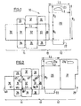
- Figure 1 represents a first embodiment according to the invention.
- Figure 2 represents a second embodiment according to the invention.
- Figure 3 represents a third embodiment according to the invention.
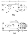
- Figure 4 represents a fourth embodiment according to the invention wherein the case is arranged inside the hooking tab.
- Figure 5 represents a fifth embodiment according to the invention similar to that shown in Figure 4.
- Figure 6 represents a sixth embodiment according to the invention similar to that shown in Figure 1 wherein the part of the blank used to form the case is hinged directly to the part of the blank used to form the display card.
- Figure 7 represents a perspective view of the pack obtained from a blank according to the invention.
- Figure 8 represents the cross-section of the pack according to the invention represented in Figure 7 at the level of the opening 8b.
- the invention proposes the provision of a pack 2 comprising a case 4 fitted with a display card 6 and whose openings 8a, 8b are closed by flaps.
- the case is formed from a single blank 10 preferably cardboard.
- the blank comprises a series of elements, panels and flaps all hinged one to another.
- the blank 10 comprises a first part 11 intended to form the case 4, a second part 12 intended to form the display card 6, and possibly a third part 13 enabling the position of the case to be distanced from the edges of the display card 6.
- the case 4 comprises a body 4 defined by four practically rectangular elements 30, 31, 32, 33.
- the first element 30, used for the rear, is intended to fix the case onto the second part 12 which forms the display card.
- the second element 31, hinged to one 41 of the edges (Fig. 2) of the first element, defines one side of the case 4.
- the third element 32, hinged to the second element by the edge 42 (Fig. 2) opposite that used for hinging between the first element and the second element, defines the front of the case.
- the fourth element 33 hinged to the third element by the edge 43 (Fig. 2) opposite that used for hinging between the third element and the second element, defines the other side of the case.
- the edge 40 (Fig. 2), of the edges of the first element 30 opposite the edge used for hinging between the first and second element, is brought very near to the edge 44 of the fourth element 33 opposite the edge 43 used for hinging between the third and the fourth elements, in such a way as to form a tube of practically rectangular cross-section defining two openings 8a and 8b.
- the opposing edges 45 and 46 (Fig. 2) of the second element 31 defining part of the openings 8a and 8b, are each provided with a closing flap 34 and 35 respectively.
- the opposing edges 47 and 48 (Fig. 2) of the third element 32 defining part of the openings 8a and 8b, are each provided with a closing flap 36 and 37 respectively.
- the opposing edges 49 and 50 (Fig. 2) of the fourth element 33 defining part of the openings 8a and 8b, are each provided with a closing flap 38 and 39 respectively.
- the closing flaps 35 to 39 enable the openings 8a and 8b to be closed (Fig. 7).
- the second part comprises a first panel 20 having a first zone, intended to receive the rear 30 of the case 4.
- This first zone has a height at least equal to the height H1 of the case 4 and a width at least equal to the width L1 of the case.
- the first panel 20 also has a second zone, adjacent to the first zone, of height H2 and width L2 usually equal to the width of the first zone.
- This second zone is provided with a hooking aperture 23 whose shape is usually that of an isosceles triangle and whose point is directed towards the adjacent side which is arranged opposite the first zone. This aperture is used for hooking the pack onto the display stand.
- the second part 12 is provided, according to the invention, with a fixing flap 22 hinged to the first panel 20.
- This flap 22 is arranged in such a way as to be fixed to at least one of the closing flaps of the case 4 when the case, once filled, is closed. In this way, when the case is closed, the fixing of the four flaps 34, 36, 38 and 22 increases the fixing of the case 4 on the display card 6.
- the first part 11 of the blank 10 making the case 4 is linked to the second part 12 making the display card 6 by a distancing spacer 28 enabling the case 4 to be distanced from the edge of the display card 6. It will be noticed that the position of the hinged fixing flap 22 on the display card 6 is a function of the dimension separating the first part 11 of the blank 10 making the case 4 from the second part 12 making the display card 6.
- This first embodiment wherein the display card only comprises a single panel has a disadvantage because for the whole pack the visible sides of the case are obtained with the back of the blank 10 while the visible face of the display card is obtained with the front of the blank 10. If a uniform presentation is desired then both faces of the blank must be printed.
- a pack can be produced according to the invention with an improved blank 10 like for example that represented in Figure 2.
- This second embodiment only differs from the previous one by the different production of the display card.
- the display card 6 is provided with a second panel 21, practically identical to the first panel and hinged to the latter by the edge opposite to that on which the third part 13 is hinged.
- the second panel 21 has a hooking aperture 23b corresponding in position, in shape and size to the hooking aperture 23a of the first panel 20.
- the interaction of the apertures 23a and 23b defines the hooking aperture 23.
- the second panel 21 is provided with a cutout 29 in order to prevent over thickening of the card at the spacer 28 position when the pack 2 is formed. It is clear that it would also be possible to choose to hinge the second panel 21 onto the edge of the first panel adjacent to the hooking aperture 23.
- the third embodiment, represented in Figure 3 demonstrates that the orientation of the case 4 can easily be controlled by the location of the first part 11 of the blank 10 making the case 4 in relation to the second part 12 of the blank 10 making the display card 6.
- the first part 11 of the blank 10 is similar to that used in the embodiments described above.
- the second part 12 of the blank 10 is obtained as in the second embodiment essentially from two practically identical panels 20, 21 each having a hooking aperture 23a and 23b respectively.
- the two panels are hinged by one edge and can be folded one against the other so as to form the display card 6 and give it the same appearance as that of the case 4.
- the first part 11 making the case 4 is linked to the second part 12 making the display card 6 by a third part 13 used as spacer 28.
- the length of the spacer is greater than the corresponding dimension of the case 4 and is equal to the dimension of the display card 6.
- the panel 21, on which the element 31 of the case, making the rear of this case, will be fixed, is provided with two fixing flaps 22a and 22b extending beyond the periphery of the display card 6 and intended to be fixed to at least one closing flap of the opening of the case 4.
- the panel 20, to which the panel 21 having flaps 22 is fixed is provided with two flaps 24a and 24b intended to be folded and fixed to the panel 21 with the aim of providing the same appearance to the part uncovered by the flaps 22a and 22b when the latter are fixed to the closing flaps 34 to 39 intended for closing the case.
- the fixing flaps 22a and 22b used to improve the fixing of the case to the display card are part of the panel used for the front of the display card, and not, as in the embodiments represented in Figures 1 to 3, part of the panel used for the rear.
- the display card 6 can be obtained by the interaction of one main rear panel 20 having a hooking aperture 23a and several other panels.
- One main front panel 21 with fixing flaps 22a an 22b and a hooking aperture 23b interact with the hooking aperture 23a.
- Two presentation flaps 24a and 24b interact with the spacer 28 to improve the presentation of the front of the display card 6.
- FIG. 6 The embodiment represented in Figure 6 is similar to that of Figure 2. However, this embodiment demonstrates that when the case 4 is arranged in one corner of the display card, the third part 13 of the blank 10 is not necessary.
- the panel 21 is glued and folded according to the score line between the panels 20 and 21. Then, the blank is folded according to the score line 42 between the element 32 and the element 31, then the first zone of the second panel 21 is glued and the blank is folded according to the score line between the first panel 20 and either the third part 13 or the side element 33 when there is no third part.
- the packaging machine in the usual way folds the preformed pack that is supplied to it flat, closes one 8b of the two openings (that of the two openings having four flaps) by putting the fixing flap 22 between the side flaps 34, 38 and the closing flap 36 hinged on the front. Then, the four flaps are fixed to one another, the product to be marketed is introduced in the case thus formed, and the other opening 8a having three flaps 35, 37, 39 is closed in the embodiments represented in Figures 1, 2, 3 and 6, or the four flaps in the embodiments represented in Figures 4 and 5.
- the fixing flap 22 is fixed to the flap 36 hinged on the front of the case by one glue line 52.
- the case flaps can have an appropriate cutout that can have a shape near to that represented in Figure 4 or 5.
- the fixing flap 22 will have, for example, the shape represented in Figure 3 and should only cover a small part of the opening as can be seen in Figure 8.
Landscapes
- Engineering & Computer Science (AREA)
- Mechanical Engineering (AREA)
- Cartons (AREA)
Abstract
Description
- The present invention relates to the packaging field and in particular to cardboard packs intended to be hooked to display stands. More specifically, the pack can be in cardboard or in another easily biodegradable or recyclable material, and have a display card having a hooking aperture, and in which the fixing of the case to the display card is improved; the manufacturing operations, the introduction of objects to be packaged in the case and the closing of the case being able to be done by simple mechanisms.
- The documents DE-A-43 22 555 and US-A-4 106 615 describe cases produced from a single cardboard blank. The cases have tabs intended for hooking them to display stands. When the objects to be distributed are relatively small, such as for example photographic rollfilms, the packs are small and can easily fit in a pocket. To prevent the disappearance of articles inside a store, it has been proposed, as described in the document US-A-3 480 138, to stick small cases onto cardboard cards of a larger size. Then, it has been proposed to use a single blank for the case and for the display card. The Patent DE-A-42 22 448 proposes a pack wherein the display card is larger than the case and has an opening equal to that of the formed case. In addition, the part making the case is linked to the part making the card by a spacer, thus enabling the case to be put inside the opening provided in the display card. This embodiment is difficult to produce automatically as the case is introduced in an opening after the formation of the case and its filling. Thus in French Patent 2 743 542 a pack has been proposed that can be produced from a single cardboard blank wherein the case is stuck on the display card, which does not have such disadvantages.
- Nevertheless, it has been noted that the use of this type of cardboard pack on display cards has a disadvantage. Pulling relatively gently on the case causes the case and the card to become unstuck and gives relatively easy access to the product contained in the case.
- For ecology needs, it is advantageous to be able to produce such a pack from cardboard wherein the fixing of the case to the display card is improved. It is clear that the operations of case forming, case filling and case closing must be easy to do using conventional machines.
- The pack for the display stand according to the invention is obtained by means of a single blank having a first part intended to form the case, a second part intended to form a display card whose area is greater than the straight forward projection of the case on this card, and possibly a third part intended to distance the case from the edges of the hooking tab. The case, once formed, comprises a body defining at least one opening and closing flaps intended to close this opening. The display card comprises at least one fixing flap extending beyond- the periphery of the display card and intended to be fixed to at least one of the closing flaps so as to increase the link between the case and the display card when the case formed on the hooking tab is closed.
- Other advantages of the invention will appear on reading the description below with reference to the annexed drawings.
- Figure 1 represents a first embodiment according to the invention.
- Figure 2 represents a second embodiment according to the invention.
- Figure 3 represents a third embodiment according to the invention.
- Figure 4 represents a fourth embodiment according to the invention wherein the case is arranged inside the hooking tab.
- Figure 5 represents a fifth embodiment according to the invention similar to that shown in Figure 4.
- Figure 6 represents a sixth embodiment according to the invention similar to that shown in Figure 1 wherein the part of the blank used to form the case is hinged directly to the part of the blank used to form the display card.
- Figure 7 represents a perspective view of the pack obtained from a blank according to the invention.
- Figure 8 represents the cross-section of the pack according to the invention represented in Figure 7 at the level of the opening 8b.
- Identical references have been used on all the figures to indicate parts having identical functions.
- As can be seen in Figure 7, the invention proposes the provision of a pack 2 comprising a
case 4 fitted with adisplay card 6 and whoseopenings - As can be seen in Figures 1 to 5, the case is formed from a single blank 10 preferably cardboard. Clearly any other material can be used, however easy-to-recycle materials will be preferred. The blank comprises a series of elements, panels and flaps all hinged one to another. The blank 10 comprises a
first part 11 intended to form thecase 4, asecond part 12 intended to form thedisplay card 6, and possibly athird part 13 enabling the position of the case to be distanced from the edges of thedisplay card 6. - There now follows a description of the
first part 11 of the blank 10 enabling thecase 4 to be produced. Thecase 4 comprises abody 4 defined by four practicallyrectangular elements first element 30, used for the rear, is intended to fix the case onto thesecond part 12 which forms the display card. Thesecond element 31, hinged to one 41 of the edges (Fig. 2) of the first element, defines one side of thecase 4. Thethird element 32, hinged to the second element by the edge 42 (Fig. 2) opposite that used for hinging between the first element and the second element, defines the front of the case. Thefourth element 33, hinged to the third element by the edge 43 (Fig. 2) opposite that used for hinging between the third element and the second element, defines the other side of the case. When the case is formed, the edge 40 (Fig. 2), of the edges of thefirst element 30 opposite the edge used for hinging between the first and second element, is brought very near to the edge 44 of thefourth element 33 opposite the edge 43 used for hinging between the third and the fourth elements, in such a way as to form a tube of practically rectangular cross-section defining twoopenings - The
opposing edges 45 and 46 (Fig. 2) of thesecond element 31 defining part of theopenings closing flap opposing edges 47 and 48 (Fig. 2) of thethird element 32 defining part of theopenings closing flap fourth element 33 defining part of theopenings closing flap closing flaps 35 to 39 enable theopenings - There now follows a description of the
second part 12 intended to form thedisplay card 6. - In a first embodiment, shown in Figure 1, the second part comprises a
first panel 20 having a first zone, intended to receive the rear 30 of thecase 4. This first zone has a height at least equal to the height H1 of thecase 4 and a width at least equal to the width L1 of the case. Thefirst panel 20 also has a second zone, adjacent to the first zone, of height H2 and width L2 usually equal to the width of the first zone. This second zone is provided with ahooking aperture 23 whose shape is usually that of an isosceles triangle and whose point is directed towards the adjacent side which is arranged opposite the first zone. This aperture is used for hooking the pack onto the display stand. - The
second part 12 is provided, according to the invention, with afixing flap 22 hinged to thefirst panel 20. Thisflap 22 is arranged in such a way as to be fixed to at least one of the closing flaps of thecase 4 when the case, once filled, is closed. In this way, when the case is closed, the fixing of the fourflaps case 4 on thedisplay card 6. - In this first embodiment, the
first part 11 of the blank 10 making thecase 4 is linked to thesecond part 12 making thedisplay card 6 by adistancing spacer 28 enabling thecase 4 to be distanced from the edge of thedisplay card 6. It will be noticed that the position of the hingedfixing flap 22 on thedisplay card 6 is a function of the dimension separating thefirst part 11 of the blank 10 making thecase 4 from thesecond part 12 making thedisplay card 6. - This first embodiment wherein the display card only comprises a single panel has a disadvantage because for the whole pack the visible sides of the case are obtained with the back of the blank 10 while the visible face of the display card is obtained with the front of the blank 10. If a uniform presentation is desired then both faces of the blank must be printed.
- To prevent such an operation a pack can be produced according to the invention with an improved blank 10 like for example that represented in Figure 2. This second embodiment only differs from the previous one by the different production of the display card. In addition to the
first panel 20, thedisplay card 6 is provided with asecond panel 21, practically identical to the first panel and hinged to the latter by the edge opposite to that on which thethird part 13 is hinged. As can be seen in Figure 2, thesecond panel 21 has ahooking aperture 23b corresponding in position, in shape and size to thehooking aperture 23a of thefirst panel 20. When pack 2 is being formed,panel 21 is folded and fixed topanel 20. In this way, both faces of thedisplay card 6 have the same appearance which will then be identical to the appearance of the case once the case had been formed. In addition the interaction of theapertures hooking aperture 23. As can be seen thesecond panel 21 is provided with acutout 29 in order to prevent over thickening of the card at thespacer 28 position when the pack 2 is formed. It is clear that it would also be possible to choose to hinge thesecond panel 21 onto the edge of the first panel adjacent to the hookingaperture 23. - The third embodiment, represented in Figure 3 demonstrates that the orientation of the
case 4 can easily be controlled by the location of thefirst part 11 of the blank 10 making thecase 4 in relation to thesecond part 12 of the blank 10 making thedisplay card 6. - In a fourth embodiment, represented in Figure 4, the
first part 11 of the blank 10 is similar to that used in the embodiments described above. Thesecond part 12 of the blank 10 is obtained as in the second embodiment essentially from two practicallyidentical panels aperture display card 6 and give it the same appearance as that of thecase 4. As can be seen in Figure 4, thefirst part 11 making thecase 4 is linked to thesecond part 12 making thedisplay card 6 by athird part 13 used asspacer 28. In the embodiment represented, the length of the spacer is greater than the corresponding dimension of thecase 4 and is equal to the dimension of thedisplay card 6. Thepanel 21, on which theelement 31 of the case, making the rear of this case, will be fixed, is provided with two fixingflaps display card 6 and intended to be fixed to at least one closing flap of the opening of thecase 4. In a similar way and with the aim of obtaining an improved appearance of thedisplay card 6, thepanel 20, to which thepanel 21 havingflaps 22 is fixed, is provided with twoflaps 24a and 24b intended to be folded and fixed to thepanel 21 with the aim of providing the same appearance to the part uncovered by theflaps - As can be seen in the embodiment represented in Figure 5, the
display card 6 can be obtained by the interaction of one mainrear panel 20 having a hookingaperture 23a and several other panels. One mainfront panel 21 with fixingflaps 22a an 22b and a hookingaperture 23b interact with the hookingaperture 23a. Two presentation flaps 24a and 24b interact with thespacer 28 to improve the presentation of the front of thedisplay card 6. - The embodiment represented in Figure 6 is similar to that of Figure 2. However, this embodiment demonstrates that when the
case 4 is arranged in one corner of the display card, thethird part 13 of the blank 10 is not necessary. - In order to produce the pack delivered flat, for example that of the embodiment represented in Figure 2, the
panel 21 is glued and folded according to the score line between thepanels element 32 and theelement 31, then the first zone of thesecond panel 21 is glued and the blank is folded according to the score line between thefirst panel 20 and either thethird part 13 or theside element 33 when there is no third part. - To package an object, the packaging machine in the usual way folds the preformed pack that is supplied to it flat, closes one 8b of the two openings (that of the two openings having four flaps) by putting the fixing
flap 22 between the side flaps 34, 38 and theclosing flap 36 hinged on the front. Then, the four flaps are fixed to one another, the product to be marketed is introduced in the case thus formed, and theother opening 8a having threeflaps - As can be seen in Figure 8, the fixing
flap 22 is fixed to theflap 36 hinged on the front of the case by oneglue line 52. In one advantageous embodiment, the case flaps can have an appropriate cutout that can have a shape near to that represented in Figure 4 or 5. In this way the interaction between theflaps flaps flap 36 corresponding to the front using asingle glue line 54 applied to theflap 36. Clearly to be able to perform this operation the fixingflap 22 will have, for example, the shape represented in Figure 3 and should only cover a small part of the opening as can be seen in Figure 8. - Several embodiments have been described for a pack with a hooking tab. Clearly the case can be centered in relation to the
rear panel 20 of thedisplay card 6, as has been described with reference to Figures 1 to 6. However, the width of thespacer 28 enables the case to be located in the place required on the first zone ofpanel 20.
Claims (8)
- A blank (10) for a display card (6) with case (4), having a first part (11) intended to form a case having a body defining at least one opening (8a, 8b) and provided with closing flaps intended to close this opening, and a second part (12) intended to form a display card whose area is greater than the straight forward projection of the case on this card; said blank being characterized in that the second part comprises at least one fixing flap (22) extending beyond the periphery of the card and intended to be fixed to at least one of the closing flaps in such a way as to increase the link between the case and the display card when the case formed on the display card is closed.
- A blank according to Claim 1, wherein the display card comprises a first panel (20) provided with a first zone with height at least equal to the height (H1) of the case and width at least equal to the width (Ll) of the case, and a second zone, adjacent to the first part, with height H2 and width L2, the first panel being provided with a hooking aperture (23a) in its second zone; the first zone being arranged opposite the rear of the case once the case is closed.
- A blank according to Claim 2, wherein the display card also comprises at least one second panel (21), adjacent and hinged to the first panel, provided with a hooking aperture (23b) arranged so as to interact with the corresponding aperture (23a) of the first panel, and intended to be folded and fixed to the first panel.
- A blank according to Claim 1, wherein the first part comprises:a) a first element (31) used for a first lateral side provided, on two opposite sides, with two flaps hinged on this first element, these flaps being intended to close the openings of the case,b) a second element (32) used for the front, hinged to one of the sides of the first element not used by the flaps hinged to the sides of the first element, being provided, on two opposite sides, with two flaps intended to close the openings of the case,c) a third element, used for a second lateral side (33), practically identical to the first element hinged to one of the sides of the second element not used by the flaps hinged to the sides of the second element, provided, on two opposite sides, with two flaps intended to close the openings of the case, andd) a fourth element (30) used for the rear practically identical to the second element and intended to be fixed to the display card to hold the two sides and the front in position in relation to this tab.
- A blank according to any one of Claims 1 to 4, wherein the first part (11) and the second part (12) are hinged to two opposite edges of a third part (13) in such a way as to distance the case from the edges of the display card.
- A blank according to any one of Claims 1 to 5, wherein the fixing flap (22) only partially covers the opening when it is in the closed position.
- A case in cardboard with hooking tab obtained from a blank according to any one of Claims 1 to 7.
- A case according to the Claim 7, wherein the fixings are obtained by gluing.
Applications Claiming Priority (2)
| Application Number | Priority Date | Filing Date | Title |
|---|---|---|---|
| FR9905736A FR2793219B1 (en) | 1999-05-03 | 1999-05-03 | CARDBOARD PACKAGING FOR DISPLAY |
| FR9905736 | 1999-05-03 |
Publications (2)
| Publication Number | Publication Date |
|---|---|
| EP1050474A1 true EP1050474A1 (en) | 2000-11-08 |
| EP1050474B1 EP1050474B1 (en) | 2004-12-15 |
Family
ID=9545261
Family Applications (1)
| Application Number | Title | Priority Date | Filing Date |
|---|---|---|---|
| EP00420072A Expired - Lifetime EP1050474B1 (en) | 1999-05-03 | 2000-04-13 | Cardboard pack for display stand |
Country Status (4)
| Country | Link |
|---|---|
| US (1) | US6279820B1 (en) |
| EP (1) | EP1050474B1 (en) |
| DE (1) | DE60016662T2 (en) |
| FR (1) | FR2793219B1 (en) |
Families Citing this family (5)
| Publication number | Priority date | Publication date | Assignee | Title |
|---|---|---|---|---|
| US7316343B2 (en) * | 2002-07-17 | 2008-01-08 | Schering Ag | Folding box with fold-down attachment flap |
| US20040050751A1 (en) * | 2002-09-12 | 2004-03-18 | Janet Hood | Packaging for display of hairbrushes |
| US20080289994A1 (en) * | 2007-05-25 | 2008-11-27 | Bruce Bitowft | Display Carton |
| US8042779B2 (en) * | 2008-10-31 | 2011-10-25 | Outdoor Research Incorporated | Article attachment system and device |
| US9108760B2 (en) * | 2012-11-19 | 2015-08-18 | Moshe Begim | Retail sealed folding box with handle |
Citations (8)
| Publication number | Priority date | Publication date | Assignee | Title |
|---|---|---|---|---|
| US3480138A (en) | 1968-07-30 | 1969-11-25 | Newey Goodman Ltd | Display packs |
| US3985232A (en) * | 1975-05-05 | 1976-10-12 | Container Corporation Of America | Carton and display panel |
| US4106615A (en) | 1975-02-06 | 1978-08-15 | Lion Hamigaki Kabushiki Kaisha | Box blank and assembled package box for display |
| DE9201283U1 (en) * | 1992-02-03 | 1992-03-19 | Stemmler GmbH + Co. KG, 6700 Ludwigshafen | Packaging with viewing window |
| DE4222448A1 (en) | 1991-07-09 | 1993-01-14 | Minnesota Mining & Mfg | OPTICAL RECORDING MEDIUM WITH ANTISTATIC HARD COATING |
| DE4222488C1 (en) * | 1992-07-09 | 1993-10-21 | August Jung Soehne | Self-service packaging for suspension from a dispenser rod - has a card with stamped opening and structured side flap to fold over to contain the contents |
| DE4322555A1 (en) | 1993-07-07 | 1995-01-12 | Beiersdorf Ag | Reclosable, cuboid folding box and folding blank to produce it |
| FR2743542A1 (en) | 1996-01-11 | 1997-07-18 | Kodak Pathe | PACKAGING IN CARDBOARD FOR ATTACHING TO A DISPLAY |
Family Cites Families (3)
| Publication number | Priority date | Publication date | Assignee | Title |
|---|---|---|---|---|
| US3814303A (en) * | 1972-06-12 | 1974-06-04 | Graphic Arts Packaging Corp | Box blank |
| US4378903A (en) * | 1981-09-25 | 1983-04-05 | Champion International Corporation | Hanging tab with single line of adhesive and hanging hole clear of adhesive |
| US5341923A (en) * | 1993-02-05 | 1994-08-30 | Westerm Publishing Co., Inc. | Premium package |
-
1999
- 1999-05-03 FR FR9905736A patent/FR2793219B1/en not_active Expired - Fee Related
-
2000
- 2000-03-24 US US09/535,122 patent/US6279820B1/en not_active Expired - Lifetime
- 2000-04-13 DE DE60016662T patent/DE60016662T2/en not_active Withdrawn - After Issue
- 2000-04-13 EP EP00420072A patent/EP1050474B1/en not_active Expired - Lifetime
Patent Citations (8)
| Publication number | Priority date | Publication date | Assignee | Title |
|---|---|---|---|---|
| US3480138A (en) | 1968-07-30 | 1969-11-25 | Newey Goodman Ltd | Display packs |
| US4106615A (en) | 1975-02-06 | 1978-08-15 | Lion Hamigaki Kabushiki Kaisha | Box blank and assembled package box for display |
| US3985232A (en) * | 1975-05-05 | 1976-10-12 | Container Corporation Of America | Carton and display panel |
| DE4222448A1 (en) | 1991-07-09 | 1993-01-14 | Minnesota Mining & Mfg | OPTICAL RECORDING MEDIUM WITH ANTISTATIC HARD COATING |
| DE9201283U1 (en) * | 1992-02-03 | 1992-03-19 | Stemmler GmbH + Co. KG, 6700 Ludwigshafen | Packaging with viewing window |
| DE4222488C1 (en) * | 1992-07-09 | 1993-10-21 | August Jung Soehne | Self-service packaging for suspension from a dispenser rod - has a card with stamped opening and structured side flap to fold over to contain the contents |
| DE4322555A1 (en) | 1993-07-07 | 1995-01-12 | Beiersdorf Ag | Reclosable, cuboid folding box and folding blank to produce it |
| FR2743542A1 (en) | 1996-01-11 | 1997-07-18 | Kodak Pathe | PACKAGING IN CARDBOARD FOR ATTACHING TO A DISPLAY |
Also Published As
| Publication number | Publication date |
|---|---|
| FR2793219B1 (en) | 2001-07-13 |
| DE60016662T2 (en) | 2005-12-29 |
| FR2793219A1 (en) | 2000-11-10 |
| US6279820B1 (en) | 2001-08-28 |
| EP1050474B1 (en) | 2004-12-15 |
| DE60016662D1 (en) | 2005-01-20 |
Similar Documents
| Publication | Publication Date | Title |
|---|---|---|
| US4291807A (en) | Folding box | |
| CA1313852C (en) | Carton with integral display bin | |
| US6092663A (en) | Book-type carton with pull out tray | |
| US4361236A (en) | Carton for mailing and storage of checks | |
| EP1032531B1 (en) | Container for foodstuff | |
| US5074462A (en) | Carton having detachable promotional coupon on its end closure | |
| US5325960A (en) | Watch display package | |
| US3357543A (en) | Display and gift box | |
| US6068115A (en) | Package with attached leaflet | |
| US6371366B1 (en) | Collectibles display box | |
| US5515966A (en) | Carton with improved closure and display means | |
| US4201292A (en) | Dispenser carton | |
| US4258842A (en) | Cap display package | |
| US20030234252A1 (en) | Secure packaging and mailing container | |
| US6029885A (en) | Rapid assembly box | |
| US5697502A (en) | Packaging unit for notions | |
| EP1155974A1 (en) | Pack for smoker's articles | |
| US4126220A (en) | Display carton and blank therefor | |
| US5291995A (en) | Pack for notions and the like | |
| EP0784014B1 (en) | Cardboard packaging designed to be hooked onto a display rod | |
| EP1050474B1 (en) | Cardboard pack for display stand | |
| US5337948A (en) | Half-carton structure and method of forming same | |
| US6016919A (en) | Packaging container for allowing inspection of contents | |
| GB2030113A (en) | Package for the display of goods | |
| GB2139192A (en) | Flip top carton |
Legal Events
| Date | Code | Title | Description |
|---|---|---|---|
| PUAI | Public reference made under article 153(3) epc to a published international application that has entered the european phase |
Free format text: ORIGINAL CODE: 0009012 |
|
| AK | Designated contracting states |
Kind code of ref document: A1 Designated state(s): AT BE CH CY DE DK ES FI FR GB GR IE IT LI LU MC NL PT SE |
|
| AX | Request for extension of the european patent |
Free format text: AL;LT;LV;MK;RO;SI |
|
| 17P | Request for examination filed |
Effective date: 20010414 |
|
| AKX | Designation fees paid |
Free format text: AT BE CH CY DE DK ES FI FR GB GR IE IT LI LU MC NL PT SE |
|
| 17Q | First examination report despatched |
Effective date: 20030630 |
|
| GRAP | Despatch of communication of intention to grant a patent |
Free format text: ORIGINAL CODE: EPIDOSNIGR1 |
|
| RIN1 | Information on inventor provided before grant (corrected) |
Inventor name: COLLINET, MICHEL JEAN |
|
| GRAS | Grant fee paid |
Free format text: ORIGINAL CODE: EPIDOSNIGR3 |
|
| GRAA | (expected) grant |
Free format text: ORIGINAL CODE: 0009210 |
|
| RBV | Designated contracting states (corrected) |
Designated state(s): BE CH DE ES FR GB IT LI |
|
| AK | Designated contracting states |
Kind code of ref document: B1 Designated state(s): BE CH DE ES FR GB IT LI |
|
| PG25 | Lapsed in a contracting state [announced via postgrant information from national office to epo] |
Ref country code: LI Free format text: LAPSE BECAUSE OF FAILURE TO SUBMIT A TRANSLATION OF THE DESCRIPTION OR TO PAY THE FEE WITHIN THE PRESCRIBED TIME-LIMIT Effective date: 20041215 Ref country code: IT Free format text: LAPSE BECAUSE OF FAILURE TO SUBMIT A TRANSLATION OF THE DESCRIPTION OR TO PAY THE FEE WITHIN THE PRESCRIBED TIME-LIMIT;WARNING: LAPSES OF ITALIAN PATENTS WITH EFFECTIVE DATE BEFORE 2007 MAY HAVE OCCURRED AT ANY TIME BEFORE 2007. THE CORRECT EFFECTIVE DATE MAY BE DIFFERENT FROM THE ONE RECORDED. Effective date: 20041215 Ref country code: ES Free format text: LAPSE BECAUSE OF FAILURE TO SUBMIT A TRANSLATION OF THE DESCRIPTION OR TO PAY THE FEE WITHIN THE PRESCRIBED TIME-LIMIT Effective date: 20041215 Ref country code: CH Free format text: LAPSE BECAUSE OF FAILURE TO SUBMIT A TRANSLATION OF THE DESCRIPTION OR TO PAY THE FEE WITHIN THE PRESCRIBED TIME-LIMIT Effective date: 20041215 Ref country code: BE Free format text: LAPSE BECAUSE OF FAILURE TO SUBMIT A TRANSLATION OF THE DESCRIPTION OR TO PAY THE FEE WITHIN THE PRESCRIBED TIME-LIMIT Effective date: 20041215 |
|
| REG | Reference to a national code |
Ref country code: GB Ref legal event code: FG4D Ref country code: CH Ref legal event code: EP |
|
| REG | Reference to a national code |
Ref country code: IE Ref legal event code: FG4D |
|
| REF | Corresponds to: |
Ref document number: 60016662 Country of ref document: DE Date of ref document: 20050120 Kind code of ref document: P |
|
| PGFP | Annual fee paid to national office [announced via postgrant information from national office to epo] |
Ref country code: GB Payment date: 20050314 Year of fee payment: 6 |
|
| PGFP | Annual fee paid to national office [announced via postgrant information from national office to epo] |
Ref country code: FR Payment date: 20050401 Year of fee payment: 6 |
|
| PGFP | Annual fee paid to national office [announced via postgrant information from national office to epo] |
Ref country code: DE Payment date: 20050429 Year of fee payment: 6 |
|
| REG | Reference to a national code |
Ref country code: CH Ref legal event code: PL |
|
| PLBE | No opposition filed within time limit |
Free format text: ORIGINAL CODE: 0009261 |
|
| STAA | Information on the status of an ep patent application or granted ep patent |
Free format text: STATUS: NO OPPOSITION FILED WITHIN TIME LIMIT |
|
| ET | Fr: translation filed | ||
| 26N | No opposition filed |
Effective date: 20050916 |
|
| PG25 | Lapsed in a contracting state [announced via postgrant information from national office to epo] |
Ref country code: DE Free format text: LAPSE BECAUSE OF THE APPLICANT RENOUNCES Effective date: 20060221 |
|
| PG25 | Lapsed in a contracting state [announced via postgrant information from national office to epo] |
Ref country code: GB Free format text: LAPSE BECAUSE OF NON-PAYMENT OF DUE FEES Effective date: 20060413 |
|
| GBPC | Gb: european patent ceased through non-payment of renewal fee |
Effective date: 20060413 |
|
| REG | Reference to a national code |
Ref country code: FR Ref legal event code: ST Effective date: 20061230 |
|
| PG25 | Lapsed in a contracting state [announced via postgrant information from national office to epo] |
Ref country code: FR Free format text: LAPSE BECAUSE OF NON-PAYMENT OF DUE FEES Effective date: 20060502 |