EP1050240A1 - Device for foldably connecting a supporting leg to a piece of furniture - Google Patents
Device for foldably connecting a supporting leg to a piece of furniture Download PDFInfo
- Publication number
- EP1050240A1 EP1050240A1 EP99830268A EP99830268A EP1050240A1 EP 1050240 A1 EP1050240 A1 EP 1050240A1 EP 99830268 A EP99830268 A EP 99830268A EP 99830268 A EP99830268 A EP 99830268A EP 1050240 A1 EP1050240 A1 EP 1050240A1
- Authority
- EP
- European Patent Office
- Prior art keywords
- leg
- supporting element
- operating position
- plate
- spacer
- Prior art date
- Legal status (The legal status is an assumption and is not a legal conclusion. Google has not performed a legal analysis and makes no representation as to the accuracy of the status listed.)
- Withdrawn
Links
- 125000006850 spacer group Chemical group 0.000 claims description 27
- 230000013011 mating Effects 0.000 claims description 4
- 238000012986 modification Methods 0.000 description 2
- 230000004048 modification Effects 0.000 description 2
- 238000010276 construction Methods 0.000 description 1
- 229940052609 legend Drugs 0.000 description 1
- 238000000034 method Methods 0.000 description 1
Images

Classifications
-
- A—HUMAN NECESSITIES
- A47—FURNITURE; DOMESTIC ARTICLES OR APPLIANCES; COFFEE MILLS; SPICE MILLS; SUCTION CLEANERS IN GENERAL
- A47B—TABLES; DESKS; OFFICE FURNITURE; CABINETS; DRAWERS; GENERAL DETAILS OF FURNITURE
- A47B3/00—Folding or stowable tables
- A47B3/08—Folding or stowable tables with legs pivoted to top or underframe
- A47B2003/0824—Folding or stowable tables with legs pivoted to top or underframe the table legs being individually collapsible against the underside of the table top
Definitions
- the present invention relates to a device for foldably connecting a supporting leg to a piece of furniture.
- the present invention relates to a device for foldably connecting a supporting_leg to a piece of furniture comprising:
- a device for foldably connecting a supporting leg to a piece of furniture known in the art is for example the device disclosed in European Patent No. EP 0 321 005.
- a foot for a piece of furniture bound to a fixing device at the bottom of the piece of furniture itself in such a way to be movable from an operating vertical position to a non-operating, substantially horizontal position, adjacent to the bottom.
- removable fixing means are foreseen, which preferably consist of at least one splined clutch, adapted to firmly fix the foot in the operating vertical position.
- the foot is first associated to the fixing means in horizontal position adjacent to the bottom by engaging an end portion thereof in a first receiving seat formed in the device; then, the foot is moved to the operating vertical position by means of a rotational movement about an axis perpendicular to the longitudinal axis thereof, with an ensuing engagement of the end portion thereof in a second receiving seat perpendicular to the first one.
- the aforesaid device allows, however, to fold the foot in its non-operating position along the single direction allowed by the position of the first receiving seat.
- the technical problem underlying the present invention is therefore that of providing a device for foldably connecting a supporting leg to a piece of furniture having structural and functional features capable to allow the correct folding of the leg, independently from the angular position of the device itself with respect to the piece of furniture.
- a device for foldably connecting a supporting leg to a piece of furniture of the kind mentioned above which is characterized in that the pivoting means of the leg comprises a supporting element rotatably mounted in an idle manner on said plate about a normal axis of the plate and in that said clamping means cooperates with said supporting element for fixing said supporting element and the leg associated therewith in said first operating position.
- normal axis of the plate is meant to indicate an axis substantially perpendicular to the plate itself.
- the clamping means beside fixing the leg in its operating position preventing the same from being folded, simultaneously allows to stop the movement of relative rotation between the plate and the leg.
- the supporting element is rotatably mounted in an idle manner on a removable spacer associated to the fixing plate.
- the spacer comprises a substantially cylindrical body provided at one end thereof with a frusto-conical portion extending from a flanged portion provided with a plurality of essentially hemispherical projections.
- the supporting element is internally provided with a substantially frusto-conical seat adapted to receive in mating engagement the frusto-conical portion of the spacer.
- the engagement between the spacer and the supporting element occurs at a cylindrical end portion of the frusto-conical portion of the spacer having a very small size and at the hemispherical projections formed on the flanged portion, advantageously allowing a reduction of the friction due to the relative rotation of the two elements. Further on, the presence of hemispherical projections enables the adjustment of the clearance between the two elements.
- the frusto-conical shape of the seat of the supporting element beside facilitating the engagement with the spacer, allows to strengthen the construction.
- the supporting element comprises an essentially cylindrical base portion and an essentially parallelepipedic shank cantilevered from the base portion, on which shank a fork element, removably associated to such leg, is rotatably mounted.
- leg folding is accomplished by rotating the fork element, integral with the leg, with respect to the supporting element about a pivoting axis substantially perpendicular to the axis of the leg.
- the free end portions of the fork element and of the shank have respective rounded edges.
- the shank of the supporting element is externally provided on opposite faces thereof with essentially hemispherical projections adapted to engage in a snap-fit manner respective holes formed in opposite faces of the fork element when the leg is in its first operating position or in the second non-operating position.
- leg's end position is univocally determined, both when the leg is folded in its non-operating position and when the leg is moved back to its operating position.
- the clamping means comprises a locking ring nut slidably mounted on the spacer and adapted to cooperate in a clutch-wise manner with the supporting element.
- the locking ring nut may be slided along the spacer until a clutching engagement on the supporting element is achieved, thereby fixing the latter in the aforesaid desired operating condition.
- the locking ring nut is provided with a plurality of teeth radially extending from an inner surface thereof and adapted to cooperate in a substantially clutch-wise manner with a plurality of counter-teeth radially extending from the supporting element.
- the locking ring nut is also provided with a plurality of angularly offset grooves and which are radially formed in an end rim of the locking ring nut, the grooves being adapted to enable the guided sliding of the locking ring nut on the substantially cylindrical body of the spacer by engaging a plurality of corresponding ribs radially extending from the aforesaid body.
- the sliding of the locking ring nut on the ribs of the spacer allows to obtain a correct clutching engagement between the teeth of the locking ring nut and the counter-teeth of the supporting element.
- the supporting element is a substantially fork element, wherein a substantially parallelepipedic shank, cantilevered from a base portion removably associated to the leg, is rotatably mounted.
- numeral 1 indicates a device for foldably connecting a supporting leg 2 to a piece of furniture conventional per se and not shown.
- the device 1 comprises a fixing plate 3, adapted to be mounted under a supporting shelf 4 of the piece of furniture by means of respective fixing means such as screws 5 conventional per se.
- the device 1 further comprises pivoting means 6 associated to the fixing plate 3, on which means the leg 2 is rotatably mounted about an axis y-y , substantially perpendicular to a longitudinal axis x-x thereof, between a first operating position, substantially perpendicular to the plate 3 and a second non-operating position, substantially parallel to the plate 3, as well as clamping means 7 for removably fixing the leg 2 in the first operating position (figure 2).
- the pivoting means 6 of the leg 2 comprises a supporting element 8 rotatably mounted in an idle manner on the plate 3 about a normal axis z-z thereof.
- the aforesaid normal axis z-z of the plate is an axis substantially perpendicular to the plate 3 itself.
- the supporting element 8 is rotatably mounted in an idle manner on a spacer 9 removably associated to the fixing plate 3 by means, for example, of a screw 15, conventional per se.
- the spacer 9 comprises a substantially cylindrical body 10 provided at one end 11 thereof with a frusto-conical portion 12 extending from a flanged portion 13 provided with a plurality of essentially hemispherical projections 14.
- the supporting element 8 is internally provided with a substantially frusto-conical seat 16 adapted to receive in mating engagement the frusto-conical portion 12 of the spacer 9.
- the supporting element 8 is associated to the spacer 9 by means, for example, of a screw 17, conventional per se, which abuts a flat portion 18 of a cylindrical portion 20 of the frusto-conical portion 12 of the spacer 9, thus enabling the free rotation of the supporting element 8 with respect to the spacer 9 itself.
- the supporting element 8 is axially provided with a through hole 19 which allows an easy access from outside in order to screw or unscrew the screw 17.
- the supporting element 8 comprises a substantially cylindrical base portion 21 and a substantially parallelepipedic shank 22 cantilevered from the base 21 and on which a fork element 23, removably associated to the leg 2, is mounted.
- the shank 22 of the supporting element 8 is externally provided on opposite faces 24 I , 24 II thereof with essentially hemispherical projections 25 adapted to engage in a snap-fit manner respective holes 26 formed in opposite walls 27 I , 27 II of the fork element 23 when the leg 2 is in the first operating position or in the second non-operating position.
- the fork element 23 is rotatably mounted on the shank 22 about the axis y-y substantially perpendicular to the longitudinal axis x-x of the leg 2 by means of a pin 28, conventional per se and is removably associated to the leg 2 itself, for example by means of a hexagonal-head screw 29, also conventional per se.
- the fork element 23 is provided with a hole 30 for receiving the screw 29 having the shape of an embedded hexagon in such a way to receive in mating engagement the head of the screw 29 and facilitate the fixing operations of the fork element 23 to the leg 2, operations which may also be accomplished without making use of any tool.
- the clamping means 7 comprises a locking ring nut 31 slidably mounted on the spacer 9 and adapted to cooperate in a clutch-wise manner with the supporting element 8.
- the locking ring nut 31 is provided with a plurality of teeth 32 radially extending from an inner wall 33 thereof and adapted to cooperate in a substantially clutch-wise manner with a plurality of counter-teeth 34 radially extending from the base portion 21 of the supporting element 8 and some of which are represented in the drawings.
- the locking ring nut 31 is further provided with a plurality of angularly offset grooves 35, radially formed in an end rim 36 of the locking ring nut 31, which are adapted to allow a guided sliding of the locking ring nut 31 on the substantially cylindrical body 10 of the spacer 9 by engaging a plurality of corresponding ribs 37 radially extending from the body 10.
- the locking ring nut 31 lies in a position capable to prevent any relative rotational movement between the supporting element 8 and the fork element 23.
- the locking ring nut 31 In a first step, in order to accomplish the folding of the leg 2, the locking ring nut 31 must be slided towards the plate 3 (see fig. 5) in such a way as to disengage the teeth 32 of the locking ring nut 31 from the counter-teeth 34 of the base portion 21 of the supporting element 8 so as to allow both the relative rotational movement between the supporting element 8 and the fork element 23 and the relative rotational movement between the supporting element 8 and the spacer 9.
- leg 2 is rotated about the axis y-y perpendicular to its longitudinal axis x-x (figure 5) in such a way as to reach the non-operating position wherein the leg is substantially parallel to the plate 3.
- leg 2 If the folding of the leg 2 is hindered by the position of other already folded legs 2, it is possible to modify the folding direction of the leg(s) 2, simply by means of a rotational movement of the leg 2 with respect to the spacer 9 about the normal axis z-z of the plate 3 (figure 5).
- leg 2 In order to bring the leg 2 back into its operating position, an opposite procedure is to be followed.
- the leg 2 is rotated about the axis y-y until the same is parallel to the normal axis z-z (fig. 4).
- the locking ring nut 31 is slided towards the leg 2 (figure 4) in such a way as to allow the engagement of the teeth 32 with the counter-teeth 34 so as to prevent both the relative rotational movement between the supporting element 8 and the fork element 23 and the relative rotational movement between the supporting element 8 and the spacer 9.
Landscapes
- Furniture Connections (AREA)
Abstract
Description
- The present invention relates to a device for foldably connecting a supporting leg to a piece of furniture.
- More specifically, the present invention relates to a device for foldably connecting a supporting_leg to a piece of furniture comprising:
- a) a fixing plate, adapted to be mounted under a supporting shelf of said piece of furniture by means of respective fixing means;
- b) pivoting means associated to said fixing plate on which means the leg is rotatably mounted about an axis substantially perpendicular to a longitudinal axis of the leg, between a first operating position, substantially perpendicular to the plate and a second non-operating position, substantially parallel to the plate, and
- c) clamping means for removably fixing the leg in said first operating -position.
-
- In the field of the pieces of furniture, in particular but not exclusively desks, tables, furniture, or the so-called "peninsulae" so widely used for furnishing kitchens, the need is well known of folding one or more legs of the piece of furniture, for example in order to facilitate the transport thereof, or to reduce its encumbrance when the piece of furniture is not used as a supporting shelf.
- A device for foldably connecting a supporting leg to a piece of furniture known in the art is for example the device disclosed in European Patent No. EP 0 321 005.
- In particular, in that patent, it is disclosed a foot for a piece of furniture bound to a fixing device at the bottom of the piece of furniture itself in such a way to be movable from an operating vertical position to a non-operating, substantially horizontal position, adjacent to the bottom. Between the foot and the fixing device, removable fixing means are foreseen, which preferably consist of at least one splined clutch, adapted to firmly fix the foot in the operating vertical position.
- In accordance with such known device, the foot is first associated to the fixing means in horizontal position adjacent to the bottom by engaging an end portion thereof in a first receiving seat formed in the device; then, the foot is moved to the operating vertical position by means of a rotational movement about an axis perpendicular to the longitudinal axis thereof, with an ensuing engagement of the end portion thereof in a second receiving seat perpendicular to the first one.
- Although substantially achieving the purpose, the aforesaid device allows, however, to fold the foot in its non-operating position along the single direction allowed by the position of the first receiving seat.
- This implies the need of mounting the devices under the bottom of the piece of furniture according to a well-defined orientation in order to allow a correct folding of the feet under the piece of furniture without causing interference between the respective non-operating positions of the feet themselves. This phenomenon of interference is particularly important whenever the aforesaid device is used for fixing legs to desks, tables and peninsulae just because of the dimension of the legs.
- The technical problem underlying the present invention is therefore that of providing a device for foldably connecting a supporting leg to a piece of furniture having structural and functional features capable to allow the correct folding of the leg, independently from the angular position of the device itself with respect to the piece of furniture.
- According to the invention, the aforesaid technical problem is solved by a device for foldably connecting a supporting leg to a piece of furniture of the kind mentioned above, which is characterized in that the pivoting means of the leg comprises a supporting element rotatably mounted in an idle manner on said plate about a normal axis of the plate and in that said clamping means cooperates with said supporting element for fixing said supporting element and the leg associated therewith in said first operating position.
- In the following description and subsequent claims the term "normal axis of the plate" is meant to indicate an axis substantially perpendicular to the plate itself.
- Advantageously, thanks to the provision of a supporting element rotatably mounted in an idle manner on the plate about a normal axis of the plate itself, it is possible to rotate the leg about the aforesaid normal axis when the leg is moved from its operating to the non-operating position, so to enable a correct positioning of the leg itself and leaving the angular orientation according to which the plate has been secured to the bottom of the piece of furniture out of consideration.
- Advantageously, furthermore, the clamping means, beside fixing the leg in its operating position preventing the same from being folded, simultaneously allows to stop the movement of relative rotation between the plate and the leg.
- According to the invention, the supporting element is rotatably mounted in an idle manner on a removable spacer associated to the fixing plate.
- Preferably, the spacer comprises a substantially cylindrical body provided at one end thereof with a frusto-conical portion extending from a flanged portion provided with a plurality of essentially hemispherical projections.
- Advantageously, the supporting element is internally provided with a substantially frusto-conical seat adapted to receive in mating engagement the frusto-conical portion of the spacer.
- In this way, the engagement between the spacer and the supporting element occurs at a cylindrical end portion of the frusto-conical portion of the spacer having a very small size and at the hemispherical projections formed on the flanged portion, advantageously allowing a reduction of the friction due to the relative rotation of the two elements. Further on, the presence of hemispherical projections enables the adjustment of the clearance between the two elements.
- Additionally, the frusto-conical shape of the seat of the supporting element, beside facilitating the engagement with the spacer, allows to strengthen the construction.
- According to a preferred embodiment, the supporting element comprises an essentially cylindrical base portion and an essentially parallelepipedic shank cantilevered from the base portion, on which shank a fork element, removably associated to such leg, is rotatably mounted.
- In this way, the leg folding is accomplished by rotating the fork element, integral with the leg, with respect to the supporting element about a pivoting axis substantially perpendicular to the axis of the leg.
- In order to allow a rotating movement of the fork element with respect to the supporting element, the free end portions of the fork element and of the shank have respective rounded edges.
- Preferably, the shank of the supporting element is externally provided on opposite faces thereof with essentially hemispherical projections adapted to engage in a snap-fit manner respective holes formed in opposite faces of the fork element when the leg is in its first operating position or in the second non-operating position.
- In this way, the leg's end position is univocally determined, both when the leg is folded in its non-operating position and when the leg is moved back to its operating position.
- For the purposes of the invention, the clamping means comprises a locking ring nut slidably mounted on the spacer and adapted to cooperate in a clutch-wise manner with the supporting element.
- In this way, once the desired operating position of the leg is reached, the locking ring nut may be slided along the spacer until a clutching engagement on the supporting element is achieved, thereby fixing the latter in the aforesaid desired operating condition.
- Preferably, the locking ring nut is provided with a plurality of teeth radially extending from an inner surface thereof and adapted to cooperate in a substantially clutch-wise manner with a plurality of counter-teeth radially extending from the supporting element.
- Preferably, the locking ring nut is also provided with a plurality of angularly offset grooves and which are radially formed in an end rim of the locking ring nut, the grooves being adapted to enable the guided sliding of the locking ring nut on the substantially cylindrical body of the spacer by engaging a plurality of corresponding ribs radially extending from the aforesaid body.
- Thanks to the provision of the aforesaid grooves, the sliding of the locking ring nut on the ribs of the spacer allows to obtain a correct clutching engagement between the teeth of the locking ring nut and the counter-teeth of the supporting element.
- According to an alternative embodiment of the invention, the supporting element is a substantially fork element, wherein a substantially parallelepipedic shank, cantilevered from a base portion removably associated to the leg, is rotatably mounted.
- Additional features and advantages of the present invention will be better apparent from the following detailed description of an embodiment thereof, which is reported for illustrative and non limiting purposes, with reference to the attached drawings. In such drawings:
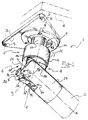
- Fig. 1 shows a perspective view of a preferred embodiment of the device according to the invention in an operating condition thereof;
- Fig. 2 shows a perspective exploded view of the device of previous fig. 1;
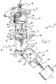
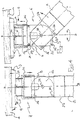
- Fig. 3 is a cross-section of the device of previous fig. 1, with the leg in its operating position;
- Fig. 4 is a front view of the device of previous fig. 1, with the leg in its operating position;
- Fig. 5 represents a front view of the device of previous fig. 1.
- With reference to such drawings,
numeral 1 indicates a device for foldably connecting a supportingleg 2 to a piece of furniture conventional per se and not shown. - The
device 1 comprises afixing plate 3, adapted to be mounted under a supportingshelf 4 of the piece of furniture by means of respective fixing means such as screws 5 conventional per se. - The
device 1 further comprises pivoting means 6 associated to thefixing plate 3, on which means theleg 2 is rotatably mounted about an axis y-y, substantially perpendicular to a longitudinal axis x-x thereof, between a first operating position, substantially perpendicular to theplate 3 and a second non-operating position, substantially parallel to theplate 3, as well as clamping means 7 for removably fixing theleg 2 in the first operating position (figure 2). - Advantageously, the pivoting means 6 of the
leg 2 comprises a supportingelement 8 rotatably mounted in an idle manner on theplate 3 about a normal axis z-z thereof. In particular, the aforesaid normal axis z-z of the plate is an axis substantially perpendicular to theplate 3 itself. - More particularly the supporting
element 8 is rotatably mounted in an idle manner on aspacer 9 removably associated to thefixing plate 3 by means, for example, of ascrew 15, conventional per se. - The
spacer 9 comprises a substantiallycylindrical body 10 provided at oneend 11 thereof with a frusto-conical portion 12 extending from aflanged portion 13 provided with a plurality of essentiallyhemispherical projections 14. - Advantageously the supporting
element 8 is internally provided with a substantially frusto-conical seat 16 adapted to receive in mating engagement the frusto-conical portion 12 of thespacer 9. - In particular, the supporting
element 8 is associated to thespacer 9 by means, for example, of ascrew 17, conventional per se, which abuts aflat portion 18 of acylindrical portion 20 of the frusto-conical portion 12 of thespacer 9, thus enabling the free rotation of the supportingelement 8 with respect to thespacer 9 itself. - In this way, the contact between the supporting
element 8 and thespacer 9 occurs along thecylindrical portion 20 and at thehemispherical projections 14, with the ensuing advantage of a substantial reduction of friction in the relative rotation of the aforesaid elements. - Preferably, the supporting
element 8 is axially provided with athrough hole 19 which allows an easy access from outside in order to screw or unscrew thescrew 17. - Advantageously, the supporting
element 8 comprises a substantiallycylindrical base portion 21 and a substantiallyparallelepipedic shank 22 cantilevered from thebase 21 and on which afork element 23, removably associated to theleg 2, is mounted. - The
shank 22 of the supportingelement 8 is externally provided onopposite faces hemispherical projections 25 adapted to engage in a snap-fit mannerrespective holes 26 formed inopposite walls fork element 23 when theleg 2 is in the first operating position or in the second non-operating position. - The
fork element 23 is rotatably mounted on theshank 22 about the axis y-y substantially perpendicular to the longitudinal axis x-x of theleg 2 by means of apin 28, conventional per se and is removably associated to theleg 2 itself, for example by means of a hexagonal-head screw 29, also conventional per se. - Advantageously, the
fork element 23 is provided with ahole 30 for receiving thescrew 29 having the shape of an embedded hexagon in such a way to receive in mating engagement the head of thescrew 29 and facilitate the fixing operations of thefork element 23 to theleg 2, operations which may also be accomplished without making use of any tool. - Preferably, the clamping means 7 comprises a
locking ring nut 31 slidably mounted on thespacer 9 and adapted to cooperate in a clutch-wise manner with the supportingelement 8. - The
locking ring nut 31 is provided with a plurality ofteeth 32 radially extending from aninner wall 33 thereof and adapted to cooperate in a substantially clutch-wise manner with a plurality ofcounter-teeth 34 radially extending from thebase portion 21 of the supportingelement 8 and some of which are represented in the drawings. - The
locking ring nut 31 is further provided with a plurality of angularlyoffset grooves 35, radially formed in anend rim 36 of thelocking ring nut 31, which are adapted to allow a guided sliding of thelocking ring nut 31 on the substantiallycylindrical body 10 of thespacer 9 by engaging a plurality ofcorresponding ribs 37 radially extending from thebody 10. - The folding of the
leg 2 from its operating position, substantially perpendicular to theplate 3, to the non-operating position, substantially parallel to theplate 3, by means of thedevice 1 of the present invention is accomplished in the way described hereinbelow. - When the
leg 2 is in its operating position (figs. 3 and 4) thelocking ring nut 31 lies in a position capable to prevent any relative rotational movement between the supportingelement 8 and thefork element 23. - In a first step, in order to accomplish the folding of the
leg 2, thelocking ring nut 31 must be slided towards the plate 3 (see fig. 5) in such a way as to disengage theteeth 32 of thelocking ring nut 31 from thecounter-teeth 34 of thebase portion 21 of the supportingelement 8 so as to allow both the relative rotational movement between the supportingelement 8 and thefork element 23 and the relative rotational movement between the supportingelement 8 and thespacer 9. - Thereafter, the
leg 2 is rotated about the axis y-y perpendicular to its longitudinal axis x-x (figure 5) in such a way as to reach the non-operating position wherein the leg is substantially parallel to theplate 3. - If the folding of the
leg 2 is hindered by the position of other already foldedlegs 2, it is possible to modify the folding direction of the leg(s) 2, simply by means of a rotational movement of theleg 2 with respect to thespacer 9 about the normal axis z-z of the plate 3 (figure 5). - In order to bring the
leg 2 back into its operating position, an opposite procedure is to be followed. Theleg 2 is rotated about the axis y-y until the same is parallel to the normal axis z-z (fig. 4). - Subsequently, the locking
ring nut 31 is slided towards the leg 2 (figure 4) in such a way as to allow the engagement of theteeth 32 with the counter-teeth 34 so as to prevent both the relative rotational movement between the supportingelement 8 and thefork element 23 and the relative rotational movement between the supportingelement 8 and thespacer 9. - Advantageously, upon reaching the aforesaid first operating position and second non-operating position of the
leg 2 thehemispherical projections 25 extending from the opposite faces 24I, 24II of theshank 22 engage in a snap-fit manner theholes 26 formed in thewalls fork element 23, so to facilitate the actual and correct positioning of theleg 2. - From what has been described and illustrated, the advantages of the present invention appear readily clear, among which it may be mentioned the possibility of correctly folding the supporting leg(s) of a piece of furniture independently of the angular position of the device with respect to the piece of furniture.
- Clearly, a man skilled in the art may introduce modifications and variants to the above disclosed device, in order to meet specific and contingent requirements of application, variants and modifications which anyway fall within the scope of protection as defined in the attached claims.
Claims (9)
- Device (1) for foldably connecting a supporting leg (2) to a piece of furniture comprising:characterized in that the pivoting means (6) of the leg (2) comprises a supporting element (8) rotatably mounted in an idle manner on said plate (3) about a normal axis (z-z) of the plate (3) and in that said clamping means (7) cooperates with said supporting element (8) for fixing said supporting element (8) and the leg (2) associated therewith in said first operating position.a) a fixing plate (3), adapted to be mounted under a supporting shelf (4) of said piece of furniture by means of respective fixing means (5);b) pivoting means (6) associated to said fixing plate (3) on which means the leg (2) is rotatably mounted about an axis (y-y), substantially perpendicular to a longitudinal axis (x-x) of the leg (2), between a first operating position, substantially perpendicular to the plate (3) and a second non-operating position, substantially parallel to the plate (3), andc) clamping means (7) for removably fixing the leg (2) in said first operating position,
- Device (1) according to claim 1, characterized in that the supporting element (8) is rotatably mounted in an idle manner on a spacer (9) removably associated to the fixing plate (3).
- Device (1) according to claim 2, characterized in that the spacer (9) comprises a substantially cylindrical body (10) provided at one end (11) thereof with a frusto-conical portion (12) extending from a flanged portion (13) provided with a plurality of essentially hemispherical projections (14).
- Device (1) according to claim 3, characterized in that the supporting element (8) is internally provided with a substantially frusto-conical seat (16) adapted to receive in mating engagement the frusto-conical portion (12) of the spacer (9).
- Device (1) according to claim 1, characterized in that said supporting element (8) comprises a substantially cylindrical base portion (21) and a substantially parallelepipedic shank (22) cantilevered from said base (21) and in that a fork element (23), removably associated to said leg 2, is rotatably mounted on said shank (22).
- Device (1) according to claim 5, characterized in that the shank (22) of the supporting element (8) is externally provided on opposite faces (24I, 24II) thereof with essentially hemispherical projections (25) adapted to engage in a snap-fit manner respective holes (26) formed in opposite walls (27I, 27II) of the fork element (23) when the leg (2) is in said first operating position or in said second non-operating position.
- Device (1) according to claim 2, characterized in that said clamping means (7) comprises a locking ring nut (31) slidably mounted on said spacer (9) and adapted to cooperate in a clutch-wise manner with the supporting element (8).
- Device (1) according to claim 7, characterized in that the locking ring nut (31) is provided with a plurality of teeth (32) radially extending from an inner wall (33) thereof and adapted to cooperate in a substantially clutch-wise manner with a plurality of counter-teeth (34) radially extending from said supporting element (8).
- Device (1) according to claims 3 and 8, characterized in that the locking ring nut (31) is provided with a plurality of angularly offset grooves (35), radially formed in an end rim (36) of the locking ring nut (31), said grooves (35) being adapted to allow a guided sliding of the locking ring nut (31) on the substantially cylindrical body (10) of the spacer (9) by engaging a plurality of corresponding ribs (37) radially extending from the body (10).
Priority Applications (1)
| Application Number | Priority Date | Filing Date | Title |
|---|---|---|---|
| EP99830268A EP1050240A1 (en) | 1999-05-06 | 1999-05-06 | Device for foldably connecting a supporting leg to a piece of furniture |
Applications Claiming Priority (1)
| Application Number | Priority Date | Filing Date | Title |
|---|---|---|---|
| EP99830268A EP1050240A1 (en) | 1999-05-06 | 1999-05-06 | Device for foldably connecting a supporting leg to a piece of furniture |
Publications (1)
| Publication Number | Publication Date |
|---|---|
| EP1050240A1 true EP1050240A1 (en) | 2000-11-08 |
Family
ID=8243392
Family Applications (1)
| Application Number | Title | Priority Date | Filing Date |
|---|---|---|---|
| EP99830268A Withdrawn EP1050240A1 (en) | 1999-05-06 | 1999-05-06 | Device for foldably connecting a supporting leg to a piece of furniture |
Country Status (1)
| Country | Link |
|---|---|
| EP (1) | EP1050240A1 (en) |
Cited By (7)
| Publication number | Priority date | Publication date | Assignee | Title |
|---|---|---|---|---|
| WO2003082051A1 (en) * | 2002-03-29 | 2003-10-09 | Leonardo S.R.L. | Fold-away legs for support surfaces. |
| EP1405580A1 (en) * | 2002-10-04 | 2004-04-07 | Sedus Stoll AG | Table with pivotable legs |
| WO2005025376A1 (en) * | 2003-09-17 | 2005-03-24 | Alu S.P.A. | A folding support structure |
| EP1523905A1 (en) | 2003-10-16 | 2005-04-20 | Sedus Stoll AG | Table with folding legs |
| DE202006014068U1 (en) * | 2006-09-13 | 2008-02-07 | Wellemöbel GmbH | Set of related components of furniture, table frame and table |
| ITVR20090175A1 (en) * | 2009-10-23 | 2011-04-24 | Enrico Targhettini | JOINT, PARTICULARLY FOR FOLDABLE LEGS |
| CN114617384A (en) * | 2022-04-02 | 2022-06-14 | 宁波市业远科技有限公司 | Gardening stool |
Citations (4)
| Publication number | Priority date | Publication date | Assignee | Title |
|---|---|---|---|---|
| US2063819A (en) * | 1934-10-04 | 1936-12-08 | George W Mattson | Portable table |
| DE1529705A1 (en) * | 1966-03-12 | 1969-05-08 | Fritz Bremshey | Mobile, cabinet-like piece of furniture |
| EP0321005A1 (en) * | 1987-11-13 | 1989-06-21 | CAMAR S.p.A. | Tuck-up foot for furniture |
| DE9400366U1 (en) * | 1994-01-11 | 1994-02-24 | Lin, Chung-I, Lu-Chou Hsiang, Taipeh | Mounting foot for electrical housings |
-
1999
- 1999-05-06 EP EP99830268A patent/EP1050240A1/en not_active Withdrawn
Patent Citations (4)
| Publication number | Priority date | Publication date | Assignee | Title |
|---|---|---|---|---|
| US2063819A (en) * | 1934-10-04 | 1936-12-08 | George W Mattson | Portable table |
| DE1529705A1 (en) * | 1966-03-12 | 1969-05-08 | Fritz Bremshey | Mobile, cabinet-like piece of furniture |
| EP0321005A1 (en) * | 1987-11-13 | 1989-06-21 | CAMAR S.p.A. | Tuck-up foot for furniture |
| DE9400366U1 (en) * | 1994-01-11 | 1994-02-24 | Lin, Chung-I, Lu-Chou Hsiang, Taipeh | Mounting foot for electrical housings |
Cited By (10)
| Publication number | Priority date | Publication date | Assignee | Title |
|---|---|---|---|---|
| WO2003082051A1 (en) * | 2002-03-29 | 2003-10-09 | Leonardo S.R.L. | Fold-away legs for support surfaces. |
| CN100339031C (en) * | 2002-03-29 | 2007-09-26 | 莱奥纳多有限责任公司 | Fold-away legs for support surfaces |
| RU2310359C2 (en) * | 2002-03-29 | 2007-11-20 | Леонардо С.р.Л. | Drop legs for support surfaces |
| US7314011B2 (en) | 2002-03-29 | 2008-01-01 | Leonardo S.R.L. | Fold-away legs for support surfaces |
| EP1405580A1 (en) * | 2002-10-04 | 2004-04-07 | Sedus Stoll AG | Table with pivotable legs |
| WO2005025376A1 (en) * | 2003-09-17 | 2005-03-24 | Alu S.P.A. | A folding support structure |
| EP1523905A1 (en) | 2003-10-16 | 2005-04-20 | Sedus Stoll AG | Table with folding legs |
| DE202006014068U1 (en) * | 2006-09-13 | 2008-02-07 | Wellemöbel GmbH | Set of related components of furniture, table frame and table |
| ITVR20090175A1 (en) * | 2009-10-23 | 2011-04-24 | Enrico Targhettini | JOINT, PARTICULARLY FOR FOLDABLE LEGS |
| CN114617384A (en) * | 2022-04-02 | 2022-06-14 | 宁波市业远科技有限公司 | Gardening stool |
Similar Documents
| Publication | Publication Date | Title |
|---|---|---|
| US6308922B1 (en) | Support assembly | |
| US6402112B1 (en) | Adjustable mechanism with locking brake | |
| EP1122486B1 (en) | Tripod | |
| CA2458152C (en) | Assist handle assembly for beds | |
| US6601806B2 (en) | System and method for leveling an appliance | |
| US8015929B2 (en) | Tray apparatus | |
| US4429918A (en) | Operatory stool | |
| EP0393473A1 (en) | A level adjustment device, paticularly for furniture | |
| CN112074210A (en) | Tool-less attachment assembly | |
| US20130119656A1 (en) | Clamp for a pipe assembly, an engagement device for the clamp, and a pipe assembly having the clamp | |
| EP1050240A1 (en) | Device for foldably connecting a supporting leg to a piece of furniture | |
| US7290741B1 (en) | Furniture glide | |
| US7578633B2 (en) | Connector for plates, particularly for shelves or trays | |
| US5711054A (en) | Fitting part or the like, more particularly a hinge part with an attachment device | |
| CN110652104B (en) | Multifunctional mounting bracket | |
| EP3512377B1 (en) | Quick assembly desk | |
| US5709157A (en) | Slidable locking mechanism for supporting a drop-leaf table extension | |
| US20090013454A1 (en) | Toilet seat elevator assembly | |
| JP2775423B2 (en) | Furniture height adjustment device | |
| US5106043A (en) | Spring and lock support for overbed table | |
| US20030172493A1 (en) | Hinge mechanism for folding table legs | |
| CA1167752A (en) | Operatory stool | |
| JP2004075040A (en) | Caster height adjusting mechanism | |
| CN216020681U (en) | Handle and cooking utensil | |
| US6196505B1 (en) | Adjustable pedestal |
Legal Events
| Date | Code | Title | Description |
|---|---|---|---|
| PUAI | Public reference made under article 153(3) epc to a published international application that has entered the european phase |
Free format text: ORIGINAL CODE: 0009012 |
|
| AK | Designated contracting states |
Kind code of ref document: A1 Designated state(s): AT BE CH DE DK ES FI FR GB GR IT LI NL PT SE |
|
| AX | Request for extension of the european patent |
Free format text: AL;LT;LV;MK;RO;SI |
|
| 17P | Request for examination filed |
Effective date: 20010331 |
|
| AKX | Designation fees paid |
Free format text: AT BE CH DE DK ES FI FR GB GR IT LI NL PT SE |
|
| 17Q | First examination report despatched |
Effective date: 20020918 |
|
| GRAP | Despatch of communication of intention to grant a patent |
Free format text: ORIGINAL CODE: EPIDOSNIGR1 |
|
| STAA | Information on the status of an ep patent application or granted ep patent |
Free format text: STATUS: THE APPLICATION IS DEEMED TO BE WITHDRAWN |
|
| 18D | Application deemed to be withdrawn |
Effective date: 20040727 |