EP1050097B1 - Rotor for an electronically commutated motor and improved method for the mass production thereof - Google Patents
Rotor for an electronically commutated motor and improved method for the mass production thereof Download PDFInfo
- Publication number
- EP1050097B1 EP1050097B1 EP99902529A EP99902529A EP1050097B1 EP 1050097 B1 EP1050097 B1 EP 1050097B1 EP 99902529 A EP99902529 A EP 99902529A EP 99902529 A EP99902529 A EP 99902529A EP 1050097 B1 EP1050097 B1 EP 1050097B1
- Authority
- EP
- European Patent Office
- Prior art keywords
- rotor
- core
- segments
- cylinder
- elastic means
- Prior art date
- Legal status (The legal status is an assumption and is not a legal conclusion. Google has not performed a legal analysis and makes no representation as to the accuracy of the status listed.)
- Expired - Lifetime
Links
- 238000004519 manufacturing process Methods 0.000 title claims description 9
- 238000000034 method Methods 0.000 title description 7
- 238000003475 lamination Methods 0.000 claims description 8
- 229910000831 Steel Inorganic materials 0.000 claims description 5
- 238000005304 joining Methods 0.000 claims description 5
- 239000000463 material Substances 0.000 claims description 5
- 239000010959 steel Substances 0.000 claims description 5
- 239000002184 metal Substances 0.000 claims description 4
- 229910052751 metal Inorganic materials 0.000 claims description 4
- 239000004411 aluminium Substances 0.000 claims description 3
- 229910052782 aluminium Inorganic materials 0.000 claims description 3
- XAGFODPZIPBFFR-UHFFFAOYSA-N aluminium Chemical compound [Al] XAGFODPZIPBFFR-UHFFFAOYSA-N 0.000 claims description 3
- 230000002452 interceptive effect Effects 0.000 claims description 3
- 239000000696 magnetic material Substances 0.000 claims description 3
- 238000003780 insertion Methods 0.000 description 5
- 230000037431 insertion Effects 0.000 description 5
- 238000005057 refrigeration Methods 0.000 description 3
- 239000000853 adhesive Substances 0.000 description 2
- 230000001070 adhesive effect Effects 0.000 description 2
- 230000002093 peripheral effect Effects 0.000 description 2
- 238000003825 pressing Methods 0.000 description 2
- 229910000589 SAE 304 stainless steel Inorganic materials 0.000 description 1
- 238000010276 construction Methods 0.000 description 1
- 238000004512 die casting Methods 0.000 description 1
- 230000005415 magnetization Effects 0.000 description 1
- 239000007769 metal material Substances 0.000 description 1
- 239000003507 refrigerant Substances 0.000 description 1
- 238000005245 sintering Methods 0.000 description 1
- 229910001220 stainless steel Inorganic materials 0.000 description 1
- 239000010935 stainless steel Substances 0.000 description 1
Images

Classifications
-
- H—ELECTRICITY
- H02—GENERATION; CONVERSION OR DISTRIBUTION OF ELECTRIC POWER
- H02K—DYNAMO-ELECTRIC MACHINES
- H02K1/00—Details of the magnetic circuit
- H02K1/06—Details of the magnetic circuit characterised by the shape, form or construction
- H02K1/22—Rotating parts of the magnetic circuit
- H02K1/27—Rotor cores with permanent magnets
- H02K1/2706—Inner rotors
- H02K1/272—Inner rotors the magnetisation axis of the magnets being perpendicular to the rotor axis
- H02K1/274—Inner rotors the magnetisation axis of the magnets being perpendicular to the rotor axis the rotor consisting of two or more circumferentially positioned magnets
- H02K1/2753—Inner rotors the magnetisation axis of the magnets being perpendicular to the rotor axis the rotor consisting of two or more circumferentially positioned magnets the rotor consisting of magnets or groups of magnets arranged with alternating polarity
- H02K1/278—Surface mounted magnets; Inset magnets
-
- H—ELECTRICITY
- H02—GENERATION; CONVERSION OR DISTRIBUTION OF ELECTRIC POWER
- H02K—DYNAMO-ELECTRIC MACHINES
- H02K15/00—Processes or apparatus specially adapted for manufacturing, assembling, maintaining or repairing of dynamo-electric machines
- H02K15/02—Processes or apparatus specially adapted for manufacturing, assembling, maintaining or repairing of dynamo-electric machines of stator or rotor bodies
- H02K15/03—Processes or apparatus specially adapted for manufacturing, assembling, maintaining or repairing of dynamo-electric machines of stator or rotor bodies having permanent magnets
-
- Y—GENERAL TAGGING OF NEW TECHNOLOGICAL DEVELOPMENTS; GENERAL TAGGING OF CROSS-SECTIONAL TECHNOLOGIES SPANNING OVER SEVERAL SECTIONS OF THE IPC; TECHNICAL SUBJECTS COVERED BY FORMER USPC CROSS-REFERENCE ART COLLECTIONS [XRACs] AND DIGESTS
- Y10—TECHNICAL SUBJECTS COVERED BY FORMER USPC
- Y10T—TECHNICAL SUBJECTS COVERED BY FORMER US CLASSIFICATION
- Y10T29/00—Metal working
- Y10T29/49—Method of mechanical manufacture
- Y10T29/49002—Electrical device making
- Y10T29/49009—Dynamoelectric machine
-
- Y—GENERAL TAGGING OF NEW TECHNOLOGICAL DEVELOPMENTS; GENERAL TAGGING OF CROSS-SECTIONAL TECHNOLOGIES SPANNING OVER SEVERAL SECTIONS OF THE IPC; TECHNICAL SUBJECTS COVERED BY FORMER USPC CROSS-REFERENCE ART COLLECTIONS [XRACs] AND DIGESTS
- Y10—TECHNICAL SUBJECTS COVERED BY FORMER USPC
- Y10T—TECHNICAL SUBJECTS COVERED BY FORMER US CLASSIFICATION
- Y10T29/00—Metal working
- Y10T29/49—Method of mechanical manufacture
- Y10T29/49002—Electrical device making
- Y10T29/49009—Dynamoelectric machine
- Y10T29/49012—Rotor
Definitions
- the present invention refers to a rotor for electronically commutated motors.
- Electronically commutated motors are becoming increasingly popular in many applications owing to the kind of efficiency and rpm-adjustment easiness that they usually offer.
- Brushless-type electronically commutated motors are for instance being used to drive hermetic compressors of household refrigeration appliances, further to industrial equipment applications, in view of reducing the energy usage thereof.
- US-A-5 040 286 and US-A-5 237 737 desclose a substantially closed rotor with a cylindrical core of magnetic steel laminations, a plurality of magnetizable sintered segments in the form of segments of a cylinder that have approximately the same length as said core and are adapted to be adhesive-bonded on to the outer surface thereof, a retaining wrapper obtained from a welded tube of non-magnetic stainless steel. and terminal closing rings made of aluminium.
- the above cited retaining wrapper has an inside diameter that is smaller than the outside diameter of the rotor sub-assembly formed by the core and the magnetizable segments, as well as larger than the outside diameter of said terminal closing rings.
- a rotor for an electronically commutated motor is also known where circumferential direction pressing members are interposed between a plurality of segment-shaped permanent magnets having the different poles and a die-casting material is filled into the gaps where the said pressing members are accommodated.
- a further purpose of the present invention is to provide a method enabling such a rotor to be mass produced to high quality standards, at reduced production costs and with the use of relatively simple tools and equipment.
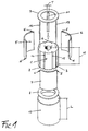
- a cylindrical stack of magnetic laminations forms the substantially cylindrical core 1 of a rotor, adapted to be joined with a shaft (not shown) which, in the case that the rotor is part of a brushless motor intended for driving a hermetic refrigerant compressor for refrigeration appliances, is in a generally known manner a common shaft for both the motor and the compressor.
- Each lamination is punched in such a manner as to ensure that three radial protrusions, for instance in the shape of a V, and six longitudinal notches with a substantially rectangular shape are provided along the periphery thereof, in addition to the usual notches and perforations that are provided to handling and centering purposes.
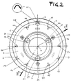
- the core 1. which is obtaining by stacking a plurality of laminations, is in this way provided with three longitudinal prismatic ribs 2, 3 and 4, spaced at 120°-angles from each other, as well as cylindrical channels 27. Only the grooves 14, 15 provided between the longitudinal ribs 2, 3 are shown in Figure 1, whereas also the grooves 16, 17 and 18, 19 provided between two other pairs of ribs 3, 4 and 4, 2, respectively, are shown in Figure 2.
- the rotor further comprises:
- a preferred method according to the present invention comprises the following phases:
- FIG. 4 A second embodiment of the rotor according to the present invention is illustrated in Figure 4.
- the rotor remains practically unchanged in the following features thereof:
- this second embodiment introduces following variants:
- the manufacturing method for this second embodiment of the rotor according to the present invention is substantially the same as the one described in connection with the afore cited first embodiment, of which it maintains the basic features and particular advantages.
- the insertion of the wrapper 36 around the rotor sub-assembly is facilitated by the fact that the inside diameter of the former is not smaller than the outside diameter of the latter; the longitudinal and radial plays that are introduced by the different dimensional tolerances of the various parts of the rotor are made up for by the retaining springs 37-42, which ensure that the outer surface of the segments of a cylinder 31, 32 and 33 is able to remain in contact with the inner surface of the wrapper 36; the action exerted by the bent, V-shaped ends of the centering springs 52, 53 and 54, owing to the interference thereof, ensures that a precise circumferential spacing is maintained between the segments of a cylinder 31, 32 and 33.
- FIG. 5 A variant of the above embodiments is illustrated in the Figures 5 to 7, in which the use is advantageously provided of a single retaining spring 60, made of steel music wire and shaped to a configuration of a "cylindric cage" instead of the plurality of the afore described elementary retaining springs.
- Said retaining spring 60 consists of:
Landscapes
- Engineering & Computer Science (AREA)
- Power Engineering (AREA)
- Manufacturing & Machinery (AREA)
- Iron Core Of Rotating Electric Machines (AREA)
- Manufacture Of Motors, Generators (AREA)
- Permanent Field Magnets Of Synchronous Machinery (AREA)
- Compressor (AREA)
Description
- Figure 1 is a simplified exploded view of a first embodiment of the rotor of an electronically commutated motor of the brushless type;
- Figure 2 is a view of the rotor of Figure 1, as seen according to the axis of rotation thereof;
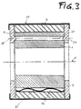
- Figure 3 is a view of the same rotor as seen along the cross-sectional line III-III of Figure 2, wherein some parts are however illustrated in a simplified manner;
- Figure 4 is a same view as the one illustrated in Figure 2, however referred to a second embodiment of the rotor;
- Figure 5 is a three-dimensional view of a magnet retaining spring that may be used in both above mentioned embodiments of the rotor;
- Figure 6 is a longitudinal view of the spring shown in Figure 5;
- Figure 7 is a cross-sectional view of the spring of Figures 5 and 6.
- three segments of a
cylinder cylinder 5. 6 and 7 are adapted to be fixed to the outer surface of thecore 1 so as to form a so-called rotor sub-assembly. For this reason, each one of said segments of acylinder core 1, in the zones comprised between thelongitudinal ribs - three
spring clips spring clip 11 associated to therib 4, thecentering springs cylinder centering springs longitudinal ribs core 1, whereas their length is preferably smaller than or equal to the height H of the core 1 (see Figure 1); - two
end rings bulges - a
cylindrical retaining wrapper 10, made of a non-magnetic metal, such as for instance AISI 304 steel, having a length L which is greater than the height H of thecore 1 and an inside diameter that is greater than or equal to the outside diameter of therings - a plurality of corrugated spring clips, that are referred to as retaining springs
and indicated at 21 through to 26 (see Figure 2) in this description, which are
made out of music steel wire. Each one of these springs is adapted to be inserted
in one of said longitudinal grooves 14-19 of the
core 1. Figure 3 shows for instance thecorrugated spring 21 inserted in thegroove 14.
- the three segments of a cylinder, made of a magnetizable material, which are
now indicated with the
reference numerals
- the two terminal rings, made of a non-magnetic material, of which only the one now indicated at 34 is shown;
- the cylindrical wrapper, which is also made of a non-magnetic metal material and is now indicated at 36;
- the retaining springs, which are now indicated at 37 through to 42.
- the
core 30, which is still formed by a stack of magnetic laminations, is provided, further to the longitudinal grooves regularly spaced from each other by an angle of 60°, and now indicated at 43 through to 48 in the Figure, for the retaining springs 37-42, with threeperipheral slots
- the three centering springs, which are now indicated at 52, 53 and 54 in the
Figure, have a cross-section in the shape of a Ω and are so sized as to be able to
be accomodated in the
peripheral slots cylinder 31. 32 and 33. These features are evidenced in the detail illustrated to an enlarged scale in Figure 4, which only shows theslot 49 and the therewith associated centeringspring 52 with itsbent end portions
- first parallelly extending portions, indicated at 61 through to 66 in the Figures, provided in an equal number as the corresponding grooves on the periphery of the rotor core (ie. six in this particular example of embodiment) - see Figures 5 and 6;
- second portions in the shape of arcs of a circle, and indicated at 67 through to 72 in the Figures, which are subdivided into two groups of equal number between the ends of said first portions 61-66 (ie. three plus three in this particular example of embodiment) - see Figure 5;
- short radial joining portions. indicated at 73 through to 84 in the Figures, which are provided between the ends of each one of said first portions 61-66 and the adjacent second portions 67-72 (see Figure 7). so that they are of course provided in a number that is the double of the number thereof (ie. in the number of twelve in this example of embodiment) - see Figure 5.
- both said first portions 61-66 and said second portions 67-72 are not rectilinear, but undulated, ie. a fact that increases the elastic yielding property thereof in all directions and, therefore, the capability thereof of making up for the different dimensional tolerances of the various parts (see Figures 5 and 6);
- the length thereof (ie. the distance between the two groups of second portions 67-72) is substantially equal to the height H of the rotor core (see Figure 5);
- the radial extension of the joining portions 73-84 is smaller than the thickness of the segments of a cylinder of the rotor sub-assembly, as measured on a plane that is orthogonal to the axis of rotation thereof.
Claims (8)
- Rotor for an electronically commutated motor that comprises:characterized in that it also comprises second elastic means (21-26; 37-42; 60), which are supported by supporting means (14-19; 43-48) that are integrally provided in the said core (1; 30), said elastic means (21-26; 37-42; 60) being adapted to make up for the longitudinal and radial plays of the various parts of the rotor so as to ensure that the outer surface of the said segments (5, 5, 7; 31, 32, 33) keeps in contact with the inner surface of the wrapper (10; 36).a sub-assembly formed by a core (1; 30) of magnetic laminations and by a plurality of segments of a cylinder (5, 6, 7; 31, 32, 33) made of preferably sintered magnetizable materials positioned on the outer surface of the core (1; 30),a substantially cylindrical wrapper (10; 36) made of a non-magnetic material, preferably an austenitic steel, surrounding said segments of a cylinder (5, 6, 7; 31, 32, 33) and having an inside diameter that is not smaller than the outside diameter of the said sub-assembly,at least a pair of plane elements (8, 9; 34, 35), in the form of rings made of a non-magnetic material, preferably aluminium, which are joined to the end portions of said wrapper (10; 36) at the extremities of the core (1; 30),first elastic means (11, 12, 13; 52, 53, 54) having a length (L) that is not smaller than the length (H) of the core (1; 30), and are supported by means (2, 3, 4; 49, 50, 51) that are integrally provided in the core (1; 30) parallelly to the axis of rotation (X) of the rotor, which are adapted to interfere with contiguous longitudinal edges of said segments of a cylinder (5, 6, 7; 31, 32, 33) so as to keep said segments circumferentially spaced from each other,
- Rotor according to claim 1, characterized in that the supporting means (14-19; 43-48) for said second elastic means (21-26; 37-42; 60) are grooves extending parallelly to the axis of rotation (X) of the rotor and provided in a number that is equal to or a multiple of the number of the supporting means (2, 3, 4; 49, 50, 51) for said first elastic means (11, 12, 13; 52, 53, 54).
- Rotor according to claim 1 or 2, characterized in that said second elastic means (21-26; 37, 42) are elementary undulated springs.
- Rotor according to any of the preceding claims, characterized in that said second elastic means (60) comprise a cylindric cage made of metal wire and consisting of first parallel, preferably undulated portions (61-66) provided in a number equal to the supporting means (14-19; 43-48) thereof, second portions (67-72) formed in the shape of arcs of a circle, and preferably undulated, which are subdivided into two groups of equal number between the ends of said first portions (61-66), and radial joining portions (73-84) that are provided between the ends of each one of said first portions (61-66) and the adjacent second portions (67-72).
- Rotor according to claim 4, characterized in that the radial extension of said radial joining portions (73-84) is smaller than the thickness of the segments of a cylinder (5, 6, 7; 31, 32, 33) as measured on a plane that is orthogonal to the axis of rotation (X) of the rotor.
- Rotor according to any of the preceding claims, characterized in that the means for supporting said first elastic means (11, 12, 13) substantially consist of peripherally arranged slots (49, 50, 51) that are provided, regularly spaced from each other, on the outer surface of the core (30) and have a cross-section in the shape of a "Ω", said slots being adapted to accomodate the first elastic means (52, 53, 54) which are also in the shape of a "Ω" with their end portions bent to the shape of a "V" interfering with the contiguous longitudinal edges of the segments of a cylinder (31, 32, 33).
- Rotor according to any of the preceding claims, characterized in that the end portions of the wrapper (10; 36) are joined to said plane elements (8, 9; 34, 35) solely by means of a simple mechanical deformation.
- Method for producing a rotor according to any of the preceding claims, comprising substantially the phases of:making the core (1; 30) by stacking a plurality of magnetic laminations;associating said second elastic means (21-26; 37-42; 60) to respective supporting means (14-19; 43-48) integrally provided on the core;obtaining a rotor sub-assembly formed by the core (1;30), said second elastic means (21-26; 37, 42; 60), and the segments of a cylinder (5, 6, 7; 31, 32, 33) arranged along the outer surface of the core (1; 30) ;inserting the cylindrical wrapper (10; 36) along the axis of rotation (X) around said rotor sub-assembly with a radial play with respect thereto;inserting said first elastic means (11, 12, 13; 52, 53, 54) in the respective supporting means provided integrally on the core (1; 30) so as to obtain a circumferential spacing of the segments of a cylinder (5, 6, 7; 31, 32, 33) from each other due to the same first elastic means (11, 12, 13; 52, 53, 54) interfering with the contiguous longitudinal edges of the segments of a cylinder (5, 6, 7; 31, 32, 33);inserting said plane elements (8, 9; 34, 35) so as to enable them to come into contact with the end portions of the core (1, 30);submitting the end portions of the wrapper (10; 36) and/or the plane elements (8, 9; 34, 35) to a circumferential mechanical deformation so as to enable them to mutually join to form a cylindrical, substantially sealed shell;magnetizing the rotor so as to enable the contiguous longitudinal edges of the segments of a cylinder (5, 6, 7; 31, 32, 33) to become opposite magnetic poles.
Priority Applications (1)
| Application Number | Priority Date | Filing Date | Title |
|---|---|---|---|
| SI9930599T SI1050097T1 (en) | 1998-01-20 | 1999-01-11 | Rotor for an electronically commutated motor and improved method for the mass production thereof |
Applications Claiming Priority (7)
| Application Number | Priority Date | Filing Date | Title |
|---|---|---|---|
| ITPN980003 IT245290Y1 (en) | 1998-01-20 | 1998-01-20 | ELECTRIC MOTOR WITHOUT BRUSHES AND HERMETIC COMPRESSOR OPERATED BY SUCH MOTOR |
| ITPN980003U | 1998-01-20 | ||
| ITPN980016U | 1998-03-10 | ||
| ITPN980016 IT245301Y1 (en) | 1998-03-10 | 1998-03-10 | ELECTRIC MOTOR WITHOUT BRUSHES PERFECTED AND COMPRESSOREERMETICO OPERATED BY SUCH MOTOR |
| ITPN980070 | 1998-10-06 | ||
| ITPN980070 IT1305522B1 (en) | 1998-10-06 | 1998-10-06 | Rotor for electronically commutated motor for e.g. industrial equipment |
| PCT/EP1999/000108 WO1999038242A1 (en) | 1998-01-20 | 1999-01-11 | Rotor for an electronically commutated motor and improved method for the mass production thereof |
Publications (2)
| Publication Number | Publication Date |
|---|---|
| EP1050097A1 EP1050097A1 (en) | 2000-11-08 |
| EP1050097B1 true EP1050097B1 (en) | 2004-04-07 |
Family
ID=27274143
Family Applications (1)
| Application Number | Title | Priority Date | Filing Date |
|---|---|---|---|
| EP99902529A Expired - Lifetime EP1050097B1 (en) | 1998-01-20 | 1999-01-11 | Rotor for an electronically commutated motor and improved method for the mass production thereof |
Country Status (10)
| Country | Link |
|---|---|
| US (1) | US6836954B1 (en) |
| EP (1) | EP1050097B1 (en) |
| JP (1) | JP2002502213A (en) |
| CN (1) | CN100379122C (en) |
| BR (1) | BR9907108A (en) |
| DE (1) | DE69916246T2 (en) |
| DK (1) | DK1050097T3 (en) |
| ES (1) | ES2220035T3 (en) |
| SK (1) | SK286168B6 (en) |
| WO (1) | WO1999038242A1 (en) |
Cited By (1)
| Publication number | Priority date | Publication date | Assignee | Title |
|---|---|---|---|---|
| EP4492639A1 (en) * | 2023-07-12 | 2025-01-15 | LG Electronics Inc. | Compressor motor and compressor including the same |
Families Citing this family (14)
| Publication number | Priority date | Publication date | Assignee | Title |
|---|---|---|---|---|
| TW513841B (en) * | 2000-04-04 | 2002-12-11 | Bosch Gmbh Robert | Rotor |
| DE10051308B4 (en) * | 2000-04-04 | 2006-07-13 | Robert Bosch Gmbh | Rotor e.g. for electric motor, has magnets held in axial and radial directions between adjacent struts compressed by outer ring |
| DE10053692A1 (en) * | 2000-10-26 | 2002-05-16 | Georgii Kobold August Heine Gm | Three-phase synchronous motor has foot of body placed in groove, and head of body abutting permanent magnet to hold it in place |
| EP1237261B1 (en) * | 2001-02-27 | 2004-04-14 | Grundfos A/S | Method for manufacturing an encapsulated rotor of a permanent magnet motor |
| GB0314553D0 (en) * | 2003-06-21 | 2003-07-30 | Weatherford Lamb | Electric submersible pumps |
| ITMI20032241A1 (en) * | 2003-11-18 | 2005-05-19 | Sisme Immobiliare S P A | ROLLER WITH PERMANENT MAGNETS FOR FAST ASSEMBLY ELECTRIC MOTOR AND METHOD FOR ITS ACHIEVEMENT |
| JP2007336737A (en) * | 2006-06-16 | 2007-12-27 | Ihi Corp | Motor rotor and method for correcting rotation balance thereof |
| JP5062464B2 (en) * | 2006-06-16 | 2012-10-31 | 株式会社Ihi | Motor rotor |
| DE202010017376U1 (en) * | 2010-08-16 | 2014-01-08 | Robert Bosch Gmbh | Attaching magnets to a rotor |
| CN102097878B (en) * | 2011-03-15 | 2012-09-05 | 哈尔滨工业大学 | Structure for fixing magnetic poles of permanent magnet motor |
| ITBO20110587A1 (en) * | 2011-10-17 | 2013-04-18 | Spal Automotive Srl | ROTOR FOR ELECTRIC MACHINE AND ITS ASSEMBLY PROCEDURE |
| DE102011088362A1 (en) * | 2011-12-13 | 2013-06-13 | Robert Bosch Gmbh | Holding element for permanent magnets on a rotor of an electric machine |
| DE102016219974B3 (en) * | 2016-10-13 | 2018-03-08 | BSH Hausgeräte GmbH | Electric drive motor |
| US10770936B2 (en) * | 2017-08-10 | 2020-09-08 | Hamilton Sundstrand Corporation | Modular permanent magnet rotor |
Family Cites Families (14)
| Publication number | Priority date | Publication date | Assignee | Title |
|---|---|---|---|---|
| DE3048337A1 (en) * | 1980-12-20 | 1982-07-29 | Robert Bosch Gmbh, 7000 Stuttgart | ELECTRICAL MACHINE, IN PARTICULAR FOR TURNING DEVICES OF INTERNAL COMBUSTION ENGINES |
| DE3105602A1 (en) * | 1981-02-16 | 1982-09-09 | Siemens AG, 1000 Berlin und 8000 München | STAND FOR A PERMANENTLY MAGNETIC ELECTRICAL MACHINE |
| US4636107A (en) * | 1982-03-30 | 1987-01-13 | Plus Manufacturing Co., Inc. | Reformed in place resilient retention springs |
| EP0143693A3 (en) * | 1983-11-18 | 1985-07-10 | FRANKLIN ELECTRIC Co., Inc. | Rotor for electric motor |
| JPS61106049A (en) * | 1984-10-25 | 1986-05-24 | Yaskawa Electric Mfg Co Ltd | Permanent magnet rotor of rotating electric machine |
| JPS6380744A (en) * | 1986-09-22 | 1988-04-11 | Mitsubishi Electric Corp | Permanent magnet rotor |
| US5237737A (en) * | 1988-06-08 | 1993-08-24 | General Electric Company | Method of making a permanent magnet rotor |
| EP0459355A1 (en) * | 1990-06-01 | 1991-12-04 | Hitachi, Ltd. | Permanent magnet type rotor |
| JPH04165932A (en) * | 1990-10-29 | 1992-06-11 | Toshiba Corp | Permanent magnet type rotor |
| JPH06133479A (en) * | 1992-09-02 | 1994-05-13 | Toshiba Corp | Permanent magnet rotor and manufacturing apparatus thereof |
| JPH06169538A (en) * | 1992-11-30 | 1994-06-14 | Matsushita Electric Works Ltd | Miniature motor |
| JPH09182332A (en) * | 1995-12-21 | 1997-07-11 | Daikin Ind Ltd | Brushless DC motor |
| JP3351237B2 (en) * | 1996-05-16 | 2002-11-25 | 三菱電機株式会社 | Permanent magnet type motor |
| US6084330A (en) * | 1998-03-13 | 2000-07-04 | Kollmorgen Corporation | Permanent magnet rotor and method of assembly |
-
1999
- 1999-01-11 EP EP99902529A patent/EP1050097B1/en not_active Expired - Lifetime
- 1999-01-11 JP JP2000529026A patent/JP2002502213A/en active Pending
- 1999-01-11 WO PCT/EP1999/000108 patent/WO1999038242A1/en not_active Ceased
- 1999-01-11 BR BR9907108-8A patent/BR9907108A/en not_active IP Right Cessation
- 1999-01-11 SK SK1060-2000A patent/SK286168B6/en unknown
- 1999-01-11 US US09/582,503 patent/US6836954B1/en not_active Expired - Fee Related
- 1999-01-11 DK DK99902529T patent/DK1050097T3/en active
- 1999-01-11 DE DE69916246T patent/DE69916246T2/en not_active Expired - Fee Related
- 1999-01-11 ES ES99902529T patent/ES2220035T3/en not_active Expired - Lifetime
- 1999-01-11 CN CNB998017949A patent/CN100379122C/en not_active Expired - Fee Related
Cited By (1)
| Publication number | Priority date | Publication date | Assignee | Title |
|---|---|---|---|---|
| EP4492639A1 (en) * | 2023-07-12 | 2025-01-15 | LG Electronics Inc. | Compressor motor and compressor including the same |
Also Published As
| Publication number | Publication date |
|---|---|
| CN100379122C (en) | 2008-04-02 |
| DE69916246D1 (en) | 2004-05-13 |
| CN1287705A (en) | 2001-03-14 |
| WO1999038242A1 (en) | 1999-07-29 |
| DK1050097T3 (en) | 2004-07-12 |
| BR9907108A (en) | 2000-10-24 |
| SK286168B6 (en) | 2008-04-07 |
| DE69916246T2 (en) | 2005-03-10 |
| ES2220035T3 (en) | 2004-12-01 |
| US6836954B1 (en) | 2005-01-04 |
| JP2002502213A (en) | 2002-01-22 |
| SK10602000A3 (en) | 2001-06-11 |
| EP1050097A1 (en) | 2000-11-08 |
Similar Documents
| Publication | Publication Date | Title |
|---|---|---|
| US6836954B1 (en) | Rotor for an electronically commutated motor and improved method for the mass production thereof | |
| JP5359192B2 (en) | Anisotropic permanent magnet motor | |
| US5371426A (en) | Rotor of brushless motor | |
| JP5958502B2 (en) | Rotor and rotating electric machine using the same | |
| EP1737105B1 (en) | Rotor of motor and manufacturing method thereof | |
| KR101372270B1 (en) | motor and manufacturing method thereof | |
| WO2010047098A1 (en) | Dual rotor motor and manufacturing method therefor | |
| KR20090055009A (en) | Permanent Magnet Motors and Hermetic Compressors and Fan Motors | |
| KR20140140185A (en) | Motor | |
| US20050223541A1 (en) | Electrical machine and method of manufacturing the same | |
| JP2003143826A (en) | Reciprocating motor | |
| JP7198807B2 (en) | Stator and motor containing same | |
| CN109546832B (en) | Brushless direct current motor and double-clutch transmission thereof | |
| KR101405225B1 (en) | Bobin and rotor of wound rotor synchronous motor using this | |
| WO2010110150A1 (en) | Permanent magnet-embedded motor | |
| JP2012016130A (en) | Rotor, motor, and method of manufacturing rotor | |
| CN110266124B (en) | Stator core and motor | |
| US20020050760A1 (en) | Brushless motor | |
| KR102565493B1 (en) | Manufacturing methods for stators, electric motors, compressors, air conditioners and stators | |
| JP2013143805A (en) | Rotor of rotary electric machine, and rotary electric machine with the same | |
| EP1966870B1 (en) | An electric motor | |
| CN215267822U (en) | Motors, electric bicycles and home appliances | |
| MXPA00004552A (en) | Rotor for an electronically commutated motor and improved method for the mass production thereof | |
| US12206289B2 (en) | Radial spoked rotor with axial assist magnets | |
| KR101964423B1 (en) | Rotor and motor having the same |
Legal Events
| Date | Code | Title | Description |
|---|---|---|---|
| PUAI | Public reference made under article 153(3) epc to a published international application that has entered the european phase |
Free format text: ORIGINAL CODE: 0009012 |
|
| 17P | Request for examination filed |
Effective date: 20000413 |
|
| AK | Designated contracting states |
Kind code of ref document: A1 Designated state(s): DE DK ES FR GB IT |
|
| AX | Request for extension of the european patent |
Free format text: SI PAYMENT 20000413 |
|
| RAP1 | Party data changed (applicant data changed or rights of an application transferred) |
Owner name: ZANUSSI ELETTROMECCANICA S.P.A. |
|
| 17Q | First examination report despatched |
Effective date: 20021115 |
|
| GRAP | Despatch of communication of intention to grant a patent |
Free format text: ORIGINAL CODE: EPIDOSNIGR1 |
|
| GRAS | Grant fee paid |
Free format text: ORIGINAL CODE: EPIDOSNIGR3 |
|
| GRAA | (expected) grant |
Free format text: ORIGINAL CODE: 0009210 |
|
| AK | Designated contracting states |
Kind code of ref document: B1 Designated state(s): DE DK ES FR GB IT |
|
| AX | Request for extension of the european patent |
Extension state: SI |
|
| REG | Reference to a national code |
Ref country code: GB Ref legal event code: FG4D |
|
| REF | Corresponds to: |
Ref document number: 69916246 Country of ref document: DE Date of ref document: 20040513 Kind code of ref document: P |
|
| REG | Reference to a national code |
Ref country code: DK Ref legal event code: T3 |
|
| ET | Fr: translation filed | ||
| REG | Reference to a national code |
Ref country code: ES Ref legal event code: FG2A Ref document number: 2220035 Country of ref document: ES Kind code of ref document: T3 |
|
| REG | Reference to a national code |
Ref country code: SI Ref legal event code: IF |
|
| PG25 | Lapsed in a contracting state [announced via postgrant information from national office to epo] |
Ref country code: GB Free format text: LAPSE BECAUSE OF NON-PAYMENT OF DUE FEES Effective date: 20050111 |
|
| PLBE | No opposition filed within time limit |
Free format text: ORIGINAL CODE: 0009261 |
|
| STAA | Information on the status of an ep patent application or granted ep patent |
Free format text: STATUS: NO OPPOSITION FILED WITHIN TIME LIMIT |
|
| 26N | No opposition filed |
Effective date: 20050110 |
|
| GBPC | Gb: european patent ceased through non-payment of renewal fee |
Effective date: 20050111 |
|
| PGFP | Annual fee paid to national office [announced via postgrant information from national office to epo] |
Ref country code: FR Payment date: 20061211 Year of fee payment: 9 |
|
| PGFP | Annual fee paid to national office [announced via postgrant information from national office to epo] |
Ref country code: DK Payment date: 20061212 Year of fee payment: 9 |
|
| PGFP | Annual fee paid to national office [announced via postgrant information from national office to epo] |
Ref country code: DE Payment date: 20061214 Year of fee payment: 9 |
|
| PGFP | Annual fee paid to national office [announced via postgrant information from national office to epo] |
Ref country code: ES Payment date: 20070112 Year of fee payment: 9 |
|
| REG | Reference to a national code |
Ref country code: DK Ref legal event code: EBP |
|
| PG25 | Lapsed in a contracting state [announced via postgrant information from national office to epo] |
Ref country code: DE Free format text: LAPSE BECAUSE OF NON-PAYMENT OF DUE FEES Effective date: 20080801 |
|
| REG | Reference to a national code |
Ref country code: SI Ref legal event code: KO00 Effective date: 20080821 |
|
| REG | Reference to a national code |
Ref country code: FR Ref legal event code: ST Effective date: 20081029 |
|
| PG25 | Lapsed in a contracting state [announced via postgrant information from national office to epo] |
Ref country code: DK Free format text: LAPSE BECAUSE OF NON-PAYMENT OF DUE FEES Effective date: 20080131 |
|
| REG | Reference to a national code |
Ref country code: ES Ref legal event code: FD2A Effective date: 20080112 |
|
| PG25 | Lapsed in a contracting state [announced via postgrant information from national office to epo] |
Ref country code: FR Free format text: LAPSE BECAUSE OF NON-PAYMENT OF DUE FEES Effective date: 20080131 |
|
| PG25 | Lapsed in a contracting state [announced via postgrant information from national office to epo] |
Ref country code: ES Free format text: LAPSE BECAUSE OF NON-PAYMENT OF DUE FEES Effective date: 20080112 |
|
| PGFP | Annual fee paid to national office [announced via postgrant information from national office to epo] |
Ref country code: IT Payment date: 20090120 Year of fee payment: 11 |
|
| PG25 | Lapsed in a contracting state [announced via postgrant information from national office to epo] |
Ref country code: IT Free format text: LAPSE BECAUSE OF NON-PAYMENT OF DUE FEES Effective date: 20100111 |