EP1049161A2 - Cooling module including a pressure relief mechanism - Google Patents
Cooling module including a pressure relief mechanism Download PDFInfo
- Publication number
- EP1049161A2 EP1049161A2 EP00104803A EP00104803A EP1049161A2 EP 1049161 A2 EP1049161 A2 EP 1049161A2 EP 00104803 A EP00104803 A EP 00104803A EP 00104803 A EP00104803 A EP 00104803A EP 1049161 A2 EP1049161 A2 EP 1049161A2
- Authority
- EP
- European Patent Office
- Prior art keywords
- housing
- pressure relief
- relief mechanism
- cooling module
- opening
- Prior art date
- Legal status (The legal status is an assumption and is not a legal conclusion. Google has not performed a legal analysis and makes no representation as to the accuracy of the status listed.)
- Granted
Links
Images


Classifications
-
- H—ELECTRICITY
- H10—SEMICONDUCTOR DEVICES; ELECTRIC SOLID-STATE DEVICES NOT OTHERWISE PROVIDED FOR
- H10W—GENERIC PACKAGES, INTERCONNECTIONS, CONNECTORS OR OTHER CONSTRUCTIONAL DETAILS OF DEVICES COVERED BY CLASS H10
- H10W40/00—Arrangements for thermal protection or thermal control
- H10W40/70—Fillings or auxiliary members in containers or in encapsulations for thermal protection or control
- H10W40/73—Fillings or auxiliary members in containers or in encapsulations for thermal protection or control for cooling by change of state
-
- F—MECHANICAL ENGINEERING; LIGHTING; HEATING; WEAPONS; BLASTING
- F16—ENGINEERING ELEMENTS AND UNITS; GENERAL MEASURES FOR PRODUCING AND MAINTAINING EFFECTIVE FUNCTIONING OF MACHINES OR INSTALLATIONS; THERMAL INSULATION IN GENERAL
- F16K—VALVES; TAPS; COCKS; ACTUATING-FLOATS; DEVICES FOR VENTING OR AERATING
- F16K17/00—Safety valves; Equalising valves, e.g. pressure relief valves
- F16K17/02—Safety valves; Equalising valves, e.g. pressure relief valves opening on surplus pressure on one side; closing on insufficient pressure on one side
- F16K17/14—Safety valves; Equalising valves, e.g. pressure relief valves opening on surplus pressure on one side; closing on insufficient pressure on one side with fracturing member
- F16K17/16—Safety valves; Equalising valves, e.g. pressure relief valves opening on surplus pressure on one side; closing on insufficient pressure on one side with fracturing member with fracturing diaphragm ; Rupture discs
-
- F—MECHANICAL ENGINEERING; LIGHTING; HEATING; WEAPONS; BLASTING
- F28—HEAT EXCHANGE IN GENERAL
- F28D—HEAT-EXCHANGE APPARATUS, NOT PROVIDED FOR IN ANOTHER SUBCLASS, IN WHICH THE HEAT-EXCHANGE MEDIA DO NOT COME INTO DIRECT CONTACT
- F28D15/00—Heat-exchange apparatus with the intermediate heat-transfer medium in closed tubes passing into or through the conduit walls ; Heat-exchange apparatus employing intermediate heat-transfer medium or bodies
- F28D15/02—Heat-exchange apparatus with the intermediate heat-transfer medium in closed tubes passing into or through the conduit walls ; Heat-exchange apparatus employing intermediate heat-transfer medium or bodies in which the medium condenses and evaporates, e.g. heat pipes
- F28D15/0233—Heat-exchange apparatus with the intermediate heat-transfer medium in closed tubes passing into or through the conduit walls ; Heat-exchange apparatus employing intermediate heat-transfer medium or bodies in which the medium condenses and evaporates, e.g. heat pipes the conduits having a particular shape, e.g. non-circular cross-section, annular
-
- H—ELECTRICITY
- H10—SEMICONDUCTOR DEVICES; ELECTRIC SOLID-STATE DEVICES NOT OTHERWISE PROVIDED FOR
- H10W—GENERIC PACKAGES, INTERCONNECTIONS, CONNECTORS OR OTHER CONSTRUCTIONAL DETAILS OF DEVICES COVERED BY CLASS H10
- H10W42/00—Arrangements for protection of devices
-
- H—ELECTRICITY
- H10—SEMICONDUCTOR DEVICES; ELECTRIC SOLID-STATE DEVICES NOT OTHERWISE PROVIDED FOR
- H10W—GENERIC PACKAGES, INTERCONNECTIONS, CONNECTORS OR OTHER CONSTRUCTIONAL DETAILS OF DEVICES COVERED BY CLASS H10
- H10W76/00—Containers; Fillings or auxiliary members therefor; Seals
- H10W76/60—Seals
-
- Y—GENERAL TAGGING OF NEW TECHNOLOGICAL DEVELOPMENTS; GENERAL TAGGING OF CROSS-SECTIONAL TECHNOLOGIES SPANNING OVER SEVERAL SECTIONS OF THE IPC; TECHNICAL SUBJECTS COVERED BY FORMER USPC CROSS-REFERENCE ART COLLECTIONS [XRACs] AND DIGESTS
- Y10—TECHNICAL SUBJECTS COVERED BY FORMER USPC
- Y10S—TECHNICAL SUBJECTS COVERED BY FORMER USPC CROSS-REFERENCE ART COLLECTIONS [XRACs] AND DIGESTS
- Y10S165/00—Heat exchange
- Y10S165/917—Pressurization and/or degassification
Definitions
- the invention relates generally to cooling for electronic devices, and more particularly to a cooling module and a method for forming a cooling module.
- Electronic devices such as power amplifiers, power supplies, multi-chip modules, electronic hybrid assemblies such as power amplifiers, microprocessors and passive components such as filters may contain heat sources which require cooling during normal operation.
- Various techniques may be used for cooling electronic devices.
- electronic devices have been cooled by natural or forced air convection which involves moving air past conduction heat sinks attached directly or indirectly to the devices.
- Two-phase thermosyphons have been developed to provide cooling for electronic devices.
- Two-phase thermosyphons typically include a cooling liquid, often a two-phase material, within a housing.
- the two-phase material typically a liquid, vaporizes when sufficient heat density is applied to the liquid in the evaporator section.
- the vapor generated in the evaporator section moves away from the liquid towards the condenser section.
- the vapor transforms back to liquid by rejecting heat to the ambient atmosphere.
- This phase-change cycle is used to spread the heat dissipated by discrete devices over a larger area, resulting in lower device temperatures compared to conventional heat sinks.
- thermosyphon In a two-phase thermosyphon, the operating temperature of the unit is dictated by a balance between the heat input to the system and the heat rejected. Based upon the resulting temperature, the thermosyphon has a corresponding internal pressure which is dictated by the fluid properties.
- a lightweight, compact design of two-phase thermosyphon typically includes a thin-shell housing with an porous structural material core that is vacuum brazed together to yield a unit with high seal integrity.
- the two-phase fluid yields a corresponding pressure that is near or below ambient conditions.
- the unit is very structurally sound.
- the internal pressure will exceed the unit's structural limits causing it to burst or structurally fail in a highly unpredictable manner.
- thermosyphon for normal operation and does not increase the unit's compact size.
- the present invention provides a cooling module, a method for forming the cooling module, and a method for relieving pressure within a cooling module.
- the cooling module includes a pressure relief mechanism that forms a seal within the cooling module. This seal is broken when a predetermined pressure within the cooling module is exceeded. The seal is broken by shearing the pressure relief mechanism along a shearing surface.
- FIG. 1 depicts a cooling module 100 including a pressure relief mechanism 200 in accordance with a preferred embodiment of the present invention.
- Cooling module 100 includes a porous structural material, not shown for clarity.
- Cooling module 100 comprises a sealed housing 105 that includes a first outer surface 107, a second outer surface 109 opposite first outer surface 107, a first inner surface, and a second inner surface.
- Cooling module 100 also includes a porous structural material disposed within housing 105.
- housing 105 includes an evaporator portion 117 and a condenser portion 119.
- the present invention also preferably provides a cooling material 121 disposed within housing 105, which is substantially within evaporator portion 117.
- Cooling material 121 is preferably a two-phase material.
- Housing 105 is preferably formed of aluminum or an aluminum alloy, but can alternately be formed of any material that can be attached to form a sealed housing. Such materials include, but are not limited to, a magnesium alloy, a zinc alloy, copper or a copper alloy, or stainless steel.
- Porous structural material preferably includes a plurality of lanced offset fins.
- Porous structural material is preferably formed of a metal foam.
- Cooling module 100 also includes a shearing surface 201 that is effective in providing a shearing edge for shearing pressure relief mechanism 200 upon exceeding a predetermined pressure within cooling module 100.
- Cooling module 100 is preferably formed utilizing the following method.
- First housing piece 123 and second housing piece 125 are formed.
- Housing pieces 123 and 125 are preferably formed from separate pieces of sheet metal, preferably aluminum.
- a brazable alloy is then deposited on housing pieces 123 and 125 at each of the interfaces in housing pieces 123 and 125 that are to be joined.
- the brazable alloy is preferably an aluminum alloy that includes magnesium and has a lower melting temperature than the aluminum that housing pieces 123 and 125 are formed of.
- Housing pieces 123 and 125 are then placed together such that the brazable alloy on each of the pieces mates. Pressure is then applied, and housing pieces 123 and 125 are placed into a vacuum brazed furnace and heated to a temperature greater than the melting point of the brazable alloy but less than the melting temperature of the metal of which housing pieces 123 and 125 are formed from. Housing piece 123 and housing piece 125 are thereby joined in such a manner that the interface joining them provides a seal that is near-hermetic.
- the term near-hermetic refers to a seal that is an order of magnitude less than a hermetic seal, preferably about 1 x 10 -7 standard atmospheres cc's/second air equivalent leak rate.
- the porous structural material is formed, preferably of an aluminum alloy. Such a porous structural material is available from Robinson Fin Machines, Inc., of Kenton, Ohio. Porous structural material is preferably placed between first housing piece 123 and second housing piece 125 prior to attaching them.
- First housing piece 123 can be attached to second housing piece 125 by any suitable method that reliably attaches the pieces and forms a hermetic seal.
- first housing piece 123 is attached to second housing piece 125 by brazing first housing piece 123 to second housing piece 125, as described above.
- first housing piece 123 is attached to second housing piece 125 by laser welding, TIG welding, ultrasonic welding, or soldering the first housing piece to the second housing piece.
- first housing piece 123 is attached to the second housing piece 125 by adhesively bonding the first housing piece to the second housing piece.
- Cooling material 121 is preferably dispensed into housing 105 after attaching first housing piece 123 to second housing piece 125. Cooling material 121 is preferably dispensed into substantially sealed housing 105 via a fill tube 122. After filling with cooling material 121, fill tube 122 is closed and sealed, by welding or the like, to form a near-hermetically sealed housing.
- Cooling material 121 is a dielectric liquid, preferably a perfluorinated carbon liquid.
- the preferred cooling material 121 is sold under the tradename "FLUORINERT” by 3M, Inc.
- cooling material 121 can be water, alcohol, or any suitable liquid that is capable of transitioning between two phases within the operating parameters of two-phase thermosyphon 100.
- Two-phase thermosyphon 100 is operably coupled to one or more heat-generating components, such as power amplifiers, power supplies, multi-chip modules, electronic hybrid assemblies such as power amplifiers, microprocessors and passive components such as filters may contain heat sources which require cooling during normal operation.
- the two-phase thermosyphon 100 is preferably aligned in a vertical orientation, such that two-phase material 121 is located in evaporator portion 117 of two-phase thermosyphon 100.
- FIGs. 2 and 3 depict views of pressure relief mechanism 200 in accordance with the preferred embodiment of the present invention.
- Pressure relief mechanism 200 is preferably disposed within housing 105.
- Pressure relief mechanism 200 preferably covers opening 203 to provide a near-hermetic seal that seals housing 105.
- opening 203 has a diameter of about 35 millimeters. In an alternate embodiment. Opening 203 has a diameter of about 41 millimeters.
- the seal formed is near-hermetic.
- Pressure relief mechanism 200 includes a shearing surface 205 that is effective to break the seal upon exceeding a predetermined pressure within housing 105.
- the preferred pressure at which the seal is broken is between about 170 and 190 pounds per square inch (absolute).
- housing 105 is formed of a first alloy and pressure relief mechanism 200 is formed of a second alloy distinct from the first alloy.
- housing 105 is formed of 6061 aluminum, and pressure relief mechanism 200 is preferably formed of 3003 aluminum.
- pressure relief mechanism 200 is formed of a boss 204 disposed within housing 105.
- Boss 204 includes a generally circular central portion 207 and a trench 209 formed about central portion 207.
- central portion 207 has a diameter of about 19 millimeters.
- central portion 207 has a diameter of about 25 millimeters.
- Boss 204 preferably includes a trench portion 211 defined by trench 209.
- Trench 209 is preferably formed by machining with a cutter.
- Trench portion 211 has a first thickness 213 and the circular portion 207 has a second thickness 215 preferably greater than first thickness 213. In the preferred embodiment, the second thickness is about 1 millimeter.
- First thickness is preferably between about 0.1 and 0.15 millimeters.
- Cooling module 100 includes a first surface 216 and a second surface 217 that is located opposite first surface 216.
- Second surface 217 preferably a depression 219 that is sized and shaped to received the boss.
- the boss and depression 219 have a width of approximately 50 millimeters.
- Cooling module 100 is preferably formed in the manner described above.
- Housing 105 is formed and includes first surface 216.
- First surface 216 includes an inner face 221 and an outer face 223.
- a cooling material preferably a two-phase material, is disposed into housing 105.
- Cooling material 121 is preferably dispensed into housing 105 after attaching first housing piece 123 to second housing piece 125. Cooling material 121 is preferably dispensed into substantially sealed housing 105 via a fill tube. After filling with cooling material 121, the fill tube is closed and sealed, by welding or the like, to form a near-hermetically sealed housing.
- Cooling material 121 is a dielectric liquid, preferably a perfluorinated carbon liquid.
- the preferred cooling material 121 is sold under the tradename "FLUORINERT” by 3M, Inc.
- cooling material 121 can be water, alcohol, or any suitable liquid that is capable of transitioning between two phases within the operating parameters of cooling module 100.
- Opening 203 is formed in first surface 216 of housing 105. Opening 203 preferably extends from inner face 221 to outer face 223 and includes shearing surface 205. Housing 105 is then sealed with pressure relief mechanism 200. Pressure relief mechanism 200 covers opening 203 to provide a seal that seals housing 105. Pressure relief mechanism 200 preferably includes shearing surface 205 that is effective to break the seal upon exceeding a predetermined pressure within housing 105. In the preferred embodiment, shearing surface 205 is formed within boss 204. In an alternate embodiment of the present invention, shearing surface 205 is formed in housing 105, as shown in FIGs. 4 and 5.
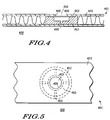
- FIGs. 4 and 5 depict views of a pressure relief mechanism 400 in accordance with an alternate embodiment of the present invention.
- Pressure relief mechanism 400 is similar to pressure relief mechanism 200, but is formed of a two-piece assembly that includes a boss 451 and a pressure relief patch 453.
- shearing surface 405 is integral with outer surface 423.
- Housing 401 is preferably sealed such that shearing surface 405 is integral with outer surface 423.
- Outer surface 423 is preferably generally planar.
- Pressure relief mechanism 400 includes boss 451 disposed proximal to opening 403. Opening 403 preferably has a diameter of about 25 millimeters. Pressure relief patch 453 is interposed between boss 451 and first surface 423 about opening 403. Pressure relief patch 453 is preferably formed of 3003 Aluminum and has a thickness of about 0.1 to about 0.15 millimeters. Boss 451 preferably includes a channel 455 to permit flow of cooling fluid 421 through boss 451 within housing 401.
- Outer surface 423 preferably has a first thickness
- pressure relief patch 453 has a second thickness that is preferably less than the first thickness.
- Pressure is relieved within cooling module 100 via the following procedure.
- Pressure relief mechanism 200 covers opening 203 and forms a seal within housing 105. This seal, which is preferably near-hermetic, is broken when a predetermined pressure exists within cooling module 100.
- the predetermined pressure is about 190 psig. In an alternate embodiment, the predetermined pressure is 170 psig.
- Such pressures are typically reached during an emergency condition that is not part of normal day-to-day operation of cooling module 100. Such emergency conditions occur, for instance, when the cooling module is exposed to a firs or other disaster that greatly exceeds the normal operating temperature of cooling module 100 and the device that is coupled to cooling module 100.
- the step of breaking the seal comprises shearing pressure relief mechanism 200 at shearing surface 205.
- the seal is broken when pressure relief mechanism 200 is sheared at shearing surface 205 formed within pressure relief mechanism 200.
- the seal is broken at shearing surface 405 formed within opening 403.
- the present invention therefore provides a cooling module, a method for forming the cooling module, and a method for relieving pressure within a cooling module.
- the cooling module in accordance with the present invention includes a pressure relief mechanism that is disposed within the housing of a cooling module.
- the pressure relief mechanism preferably seals the housing by covering an opening formed in the housing.
- the pressure relief mechanism includes a shearing surface that is effective to shear the pressure relief mechanism when a predetermined pressure is exceeded within the housing. In this manner, the pressure relief mechanism breaks the seal and prevents the cooling module from exploding or the like.
Landscapes
- Engineering & Computer Science (AREA)
- General Engineering & Computer Science (AREA)
- Mechanical Engineering (AREA)
- Life Sciences & Earth Sciences (AREA)
- Sustainable Development (AREA)
- Physics & Mathematics (AREA)
- Thermal Sciences (AREA)
- Cooling Or The Like Of Semiconductors Or Solid State Devices (AREA)
- Cooling Or The Like Of Electrical Apparatus (AREA)
Abstract
Description
Claims (13)
- A cooling module for reducing the temperature of heat-generating components, the cooling module comprising:a housing having a cooling material disposed therein, the housing including a first surface including an inner face, an outer face, and an opening extending from the inner face to the outer face;a pressure relief mechanism disposed within the housing, the pressure relief mechanism covering the opening to provide a seal that seals the housing; anda shearing surface that is effective to break the seal upon exceeding a predetermined pressure within the housing.
- A cooling module in accordance with claim 1, wherein the shearing surface is integral with the opening.
- A cooling module in accordance with claim 1, wherein the housing is formed of a first alloy and the pressure relief mechanism is formed of a second alloy distinct from the first alloy.
- A cooling module in accordance with claim 1, wherein the pressure relief mechanism includes a boss disposed proximal the opening and a pressure relief patch interposed between the boss and the first surface about the opening.
- A cooling module in accordance with claim 7, wherein the boss includes a channel to permit flow of the cooling fluid through the boss within the housing.
- A cooling module in accordance with claim 1, wherein the pressure relief mechanism is formed of a boss disposed within the housing, the boss including a generally circular central portion and a trench formed about the generally circular central portion.
- A cooling module in accordance with claim 11, wherein the housing includes a second surface opposite the first surface, and wherein the second surface includes a depression sized and shaped to received the boss.
- A cooling module in accordance with claim 11, wherein the boss includes a trench portion defined by the trench, and wherein the trench portion has a first thickness, and wherein the generally circular portion has a second thickness greater than the first thickness.
- A method for forming a cooling module including a pressure relief mechanism, the method comprising the steps of:forming a housing including a first surface including an inner face and an outer face;forming an opening in the first surface of the housing, the opening extending from the inner face to the outer face and including a shearing surface;sealing the housing with a pressure relief mechanism, the pressure relief mechanism covering the opening to provide a seal that seals the housing, the pressure relief mechanism including a shearing surface that is effective to break the seal upon exceeding a predetermined pressure within the housing; anddisposing a cooling material into the housing.
- A method for forming a cooling module including a pressure relief mechanism in accordance with claim 14, wherein the step of sealing the housing comprises the step of sealing the housing such that the shearing surface is integral with the outer surface.
- A method for relieving pressure in a cooling module including a housing and a pressure relief mechanism, the housing having a cooling material disposed therein, the housing including a first surface including an inner face, an outer face, and an opening extending from the inner face to the outer face, the opening including a shearing surface, the pressure relief mechanism disposed within the housing, the pressure relief mechanism covering the opening to provide a seal that seals the housing, the method comprising the step of breaking the seal by shearing the pressure relief mechanism upon exceeding a predetermined pressure within the housing.
- A method for relieving pressure in a cooling module in accordance with claim 17, wherein the step of breaking the seal comprises shearing the pressure relief mechanism at a shearing surface formed by the opening.
- A method for relieving pressure in a cooling module in accordance with claim 17, wherein the step of breaking the seal comprises shearing the pressure relief mechanism at a shearing surface formed within the pressure relief mechanism.
Applications Claiming Priority (2)
| Application Number | Priority Date | Filing Date | Title |
|---|---|---|---|
| US09/303,013 US6237682B1 (en) | 1999-04-30 | 1999-04-30 | Cooling module including a pressure relief mechanism |
| US303013 | 1999-04-30 |
Publications (3)
| Publication Number | Publication Date |
|---|---|
| EP1049161A2 true EP1049161A2 (en) | 2000-11-02 |
| EP1049161A3 EP1049161A3 (en) | 2001-01-17 |
| EP1049161B1 EP1049161B1 (en) | 2007-01-17 |
Family
ID=23170194
Family Applications (1)
| Application Number | Title | Priority Date | Filing Date |
|---|---|---|---|
| EP00104803A Expired - Lifetime EP1049161B1 (en) | 1999-04-30 | 2000-03-06 | Cooling module including a pressure relief mechanism |
Country Status (3)
| Country | Link |
|---|---|
| US (1) | US6237682B1 (en) |
| EP (1) | EP1049161B1 (en) |
| DE (1) | DE60032961T2 (en) |
Cited By (1)
| Publication number | Priority date | Publication date | Assignee | Title |
|---|---|---|---|---|
| WO2007001456A1 (en) * | 2004-11-24 | 2007-01-04 | General Electric Company | Heat sink with microchannel cooling for power devices |
Families Citing this family (4)
| Publication number | Priority date | Publication date | Assignee | Title |
|---|---|---|---|---|
| WO2013169774A2 (en) | 2012-05-07 | 2013-11-14 | Phononic Devices, Inc. | Thermoelectric heat exchanger component including protective heat spreading lid and optimal thermal interface resistance |
| US20130291555A1 (en) | 2012-05-07 | 2013-11-07 | Phononic Devices, Inc. | Thermoelectric refrigeration system control scheme for high efficiency performance |
| US9593871B2 (en) | 2014-07-21 | 2017-03-14 | Phononic Devices, Inc. | Systems and methods for operating a thermoelectric module to increase efficiency |
| US10458683B2 (en) | 2014-07-21 | 2019-10-29 | Phononic, Inc. | Systems and methods for mitigating heat rejection limitations of a thermoelectric module |
Family Cites Families (12)
| Publication number | Priority date | Publication date | Assignee | Title |
|---|---|---|---|---|
| US1630069A (en) * | 1922-08-16 | 1927-05-24 | Wellington W Muir | Cooling system |
| FR1346268A (en) * | 1962-05-22 | 1963-12-20 | Thomson Houston Comp Francaise | Improvements to electronic tubes cooled by vaporization in contact with an anode structure, and to the corresponding assemblies |
| US3876027A (en) * | 1973-11-21 | 1975-04-08 | George W Crise | Liquid cooled emergency brake for a motor vehicle |
| JPS5410463A (en) * | 1977-06-24 | 1979-01-26 | Hitachi Heating Appliance Co Ltd | Safeguard for heat pipe |
| US4970868A (en) * | 1989-06-23 | 1990-11-20 | International Business Machines Corporation | Apparatus for temperature control of electronic devices |
| DE4124182C1 (en) * | 1991-07-20 | 1992-06-04 | Mercedes-Benz Aktiengesellschaft, 7000 Stuttgart, De | |
| US5629840A (en) * | 1992-05-15 | 1997-05-13 | Digital Equipment Corporation | High powered die with bus bars |
| JPH0731027B2 (en) * | 1992-09-17 | 1995-04-10 | 伊藤 さとみ | Heat pipes and radiators |
| US5603892A (en) * | 1994-06-09 | 1997-02-18 | Fujitsu Limited | System for maintaining a controlled atmosphere in an electronic circuit package |
| US5768895A (en) * | 1996-05-29 | 1998-06-23 | Albertson; Luther D. | Pressure relief system and method for a refrigerator system |
| JP3843416B2 (en) * | 1996-09-13 | 2006-11-08 | 東洋電機株式会社 | Pressure relief device used for heating device with saturated steam of heating medium |
| SG64996A1 (en) * | 1997-07-08 | 1999-05-25 | Dso National Laborataries | A heat sink |
-
1999
- 1999-04-30 US US09/303,013 patent/US6237682B1/en not_active Expired - Fee Related
-
2000
- 2000-03-06 DE DE60032961T patent/DE60032961T2/en not_active Expired - Fee Related
- 2000-03-06 EP EP00104803A patent/EP1049161B1/en not_active Expired - Lifetime
Cited By (3)
| Publication number | Priority date | Publication date | Assignee | Title |
|---|---|---|---|---|
| WO2007001456A1 (en) * | 2004-11-24 | 2007-01-04 | General Electric Company | Heat sink with microchannel cooling for power devices |
| US7353859B2 (en) | 2004-11-24 | 2008-04-08 | General Electric Company | Heat sink with microchannel cooling for power devices |
| CN100559926C (en) * | 2004-11-24 | 2009-11-11 | 通用电气公司 | Heat sink with microchannel cooling for power devices |
Also Published As
| Publication number | Publication date |
|---|---|
| EP1049161A3 (en) | 2001-01-17 |
| DE60032961D1 (en) | 2007-03-08 |
| DE60032961T2 (en) | 2007-05-24 |
| US6237682B1 (en) | 2001-05-29 |
| EP1049161B1 (en) | 2007-01-17 |
Similar Documents
| Publication | Publication Date | Title |
|---|---|---|
| US11022379B2 (en) | CTE-matched heat pipe | |
| US6793009B1 (en) | CTE-matched heat pipe | |
| US20030159806A1 (en) | Flat-plate heat-pipe with lanced-offset fin wick | |
| US7143511B2 (en) | Method of forming a heat pipe | |
| EP2433480B1 (en) | Heat spreading device and method therefore | |
| EP3839400B1 (en) | Vapor chamber heatsink assembly | |
| EP3988885A1 (en) | Vapor chamber heatsink assembly | |
| US20080078531A1 (en) | Heat pipe and manufacturing method thereof | |
| US20080040925A1 (en) | Bendable heat spreader with metallic wire mesh-based microstructure and method for fabricating same | |
| US6237682B1 (en) | Cooling module including a pressure relief mechanism | |
| US20010022219A1 (en) | Plate type heat pipe and its mounting structure | |
| US6234242B1 (en) | Two-phase thermosyphon including a porous structural material having slots disposed therein | |
| US6148905A (en) | Two-phase thermosyphon including air feed through slots | |
| US20030155102A1 (en) | Vapor chamber having integral captive fasteners | |
| US7537151B2 (en) | Method of making high performance heat sinks | |
| JP4243654B2 (en) | Liquid cooling plate for electronic device parts, method for manufacturing liquid cooling plate | |
| AU6515200A (en) | Heat exchanger and method of constructing same | |
| US20020050341A1 (en) | Heat pipe heat spreader with internal solid heat conductor | |
| US20060171434A1 (en) | Semiconductor laser device and a method of mounting a semiconductor laser component on a submount | |
| EP4059647B1 (en) | Cooling heatshield for clamshell bga rework | |
| CN111278259B (en) | Radiator with built-in integrated support structure and preparation method thereof | |
| TWI801739B (en) | Temperature-uniformizing board and method for making the same | |
| EP1863085A2 (en) | Two-phase cooling system for cooling power electronic components | |
| JP7434654B1 (en) | Cold plate and cold plate manufacturing method | |
| JP2000258079A (en) | Heat dissipation structure using a flat heat pipe |
Legal Events
| Date | Code | Title | Description |
|---|---|---|---|
| PUAI | Public reference made under article 153(3) epc to a published international application that has entered the european phase |
Free format text: ORIGINAL CODE: 0009012 |
|
| AK | Designated contracting states |
Kind code of ref document: A2 Designated state(s): DE GB |
|
| AX | Request for extension of the european patent |
Free format text: AL;LT;LV;MK;RO;SI |
|
| PUAL | Search report despatched |
Free format text: ORIGINAL CODE: 0009013 |
|
| AK | Designated contracting states |
Kind code of ref document: A3 Designated state(s): AT BE CH CY DE DK ES FI FR GB GR IE IT LI LU MC NL PT SE |
|
| AX | Request for extension of the european patent |
Free format text: AL;LT;LV;MK;RO;SI |
|
| RIC1 | Information provided on ipc code assigned before grant |
Free format text: 7H 01L 23/427 A, 7H 05K 7/20 B, 7F 28D 15/02 B, 7F 16K 17/16 B |
|
| 17P | Request for examination filed |
Effective date: 20010717 |
|
| AKX | Designation fees paid |
Free format text: DE GB |
|
| 17Q | First examination report despatched |
Effective date: 20050603 |
|
| GRAP | Despatch of communication of intention to grant a patent |
Free format text: ORIGINAL CODE: EPIDOSNIGR1 |
|
| GRAS | Grant fee paid |
Free format text: ORIGINAL CODE: EPIDOSNIGR3 |
|
| GRAA | (expected) grant |
Free format text: ORIGINAL CODE: 0009210 |
|
| AK | Designated contracting states |
Kind code of ref document: B1 Designated state(s): DE GB |
|
| REG | Reference to a national code |
Ref country code: GB Ref legal event code: FG4D |
|
| PGFP | Annual fee paid to national office [announced via postgrant information from national office to epo] |
Ref country code: GB Payment date: 20070202 Year of fee payment: 8 |
|
| PGFP | Annual fee paid to national office [announced via postgrant information from national office to epo] |
Ref country code: DE Payment date: 20070228 Year of fee payment: 8 |
|
| REF | Corresponds to: |
Ref document number: 60032961 Country of ref document: DE Date of ref document: 20070308 Kind code of ref document: P |
|
| PLBE | No opposition filed within time limit |
Free format text: ORIGINAL CODE: 0009261 |
|
| STAA | Information on the status of an ep patent application or granted ep patent |
Free format text: STATUS: NO OPPOSITION FILED WITHIN TIME LIMIT |
|
| 26N | No opposition filed |
Effective date: 20071018 |
|
| GBPC | Gb: european patent ceased through non-payment of renewal fee |
Effective date: 20080306 |
|
| PG25 | Lapsed in a contracting state [announced via postgrant information from national office to epo] |
Ref country code: DE Free format text: LAPSE BECAUSE OF NON-PAYMENT OF DUE FEES Effective date: 20081001 |
|
| PG25 | Lapsed in a contracting state [announced via postgrant information from national office to epo] |
Ref country code: GB Free format text: LAPSE BECAUSE OF NON-PAYMENT OF DUE FEES Effective date: 20080306 |
|
| P01 | Opt-out of the competence of the unified patent court (upc) registered |
Effective date: 20230520 |