EP1049118A2 - Electrical apparatus having improved electrical contact and electrical contact used therewith - Google Patents
Electrical apparatus having improved electrical contact and electrical contact used therewith Download PDFInfo
- Publication number
- EP1049118A2 EP1049118A2 EP00303629A EP00303629A EP1049118A2 EP 1049118 A2 EP1049118 A2 EP 1049118A2 EP 00303629 A EP00303629 A EP 00303629A EP 00303629 A EP00303629 A EP 00303629A EP 1049118 A2 EP1049118 A2 EP 1049118A2
- Authority
- EP
- European Patent Office
- Prior art keywords
- contact
- electrical
- contacts
- layer
- insulating layer
- Prior art date
- Legal status (The legal status is an assumption and is not a legal conclusion. Google has not performed a legal analysis and makes no representation as to the accuracy of the status listed.)
- Withdrawn
Links
- 239000000835 fiber Substances 0.000 claims abstract description 16
- 239000000463 material Substances 0.000 claims description 23
- PXHVJJICTQNCMI-UHFFFAOYSA-N Nickel Chemical compound [Ni] PXHVJJICTQNCMI-UHFFFAOYSA-N 0.000 claims description 12
- BQCADISMDOOEFD-UHFFFAOYSA-N Silver Chemical compound [Ag] BQCADISMDOOEFD-UHFFFAOYSA-N 0.000 claims description 7
- 239000003365 glass fiber Substances 0.000 claims description 7
- 229910052709 silver Inorganic materials 0.000 claims description 7
- 239000004332 silver Substances 0.000 claims description 7
- 238000006073 displacement reaction Methods 0.000 claims description 6
- 239000002075 main ingredient Substances 0.000 claims description 6
- 238000007731 hot pressing Methods 0.000 claims description 5
- 229910052759 nickel Inorganic materials 0.000 claims description 4
- 238000005520 cutting process Methods 0.000 claims description 2
- 239000004020 conductor Substances 0.000 claims 3
- 238000004519 manufacturing process Methods 0.000 claims 2
- 230000001012 protector Effects 0.000 description 23
- 238000010891 electric arc Methods 0.000 description 5
- 229910052751 metal Inorganic materials 0.000 description 5
- 239000002184 metal Substances 0.000 description 5
- 239000011347 resin Substances 0.000 description 5
- 229920005989 resin Polymers 0.000 description 5
- 150000002739 metals Chemical class 0.000 description 3
- 229910045601 alloy Inorganic materials 0.000 description 2
- 239000000956 alloy Substances 0.000 description 2
- 238000007789 sealing Methods 0.000 description 2
- 229910001316 Ag alloy Inorganic materials 0.000 description 1
- 239000004677 Nylon Substances 0.000 description 1
- 230000002411 adverse Effects 0.000 description 1
- 230000003466 anti-cipated effect Effects 0.000 description 1
- 239000010953 base metal Substances 0.000 description 1
- DMFGNRRURHSENX-UHFFFAOYSA-N beryllium copper Chemical compound [Be].[Cu] DMFGNRRURHSENX-UHFFFAOYSA-N 0.000 description 1
- 230000006835 compression Effects 0.000 description 1
- 238000007906 compression Methods 0.000 description 1
- 230000008602 contraction Effects 0.000 description 1
- 230000005489 elastic deformation Effects 0.000 description 1
- 230000003628 erosive effect Effects 0.000 description 1
- 239000005357 flat glass Substances 0.000 description 1
- 239000012530 fluid Substances 0.000 description 1
- 230000020169 heat generation Effects 0.000 description 1
- 238000000034 method Methods 0.000 description 1
- 229920001778 nylon Polymers 0.000 description 1
- 238000013021 overheating Methods 0.000 description 1
- 238000002360 preparation method Methods 0.000 description 1
- 238000003466 welding Methods 0.000 description 1
Images


Classifications
-
- H—ELECTRICITY
- H01—ELECTRIC ELEMENTS
- H01H—ELECTRIC SWITCHES; RELAYS; SELECTORS; EMERGENCY PROTECTIVE DEVICES
- H01H1/00—Contacts
- H01H1/50—Means for increasing contact pressure, preventing vibration of contacts, holding contacts together after engagement, or biasing contacts to the open position
-
- H—ELECTRICITY
- H01—ELECTRIC ELEMENTS
- H01H—ELECTRIC SWITCHES; RELAYS; SELECTORS; EMERGENCY PROTECTIVE DEVICES
- H01H1/00—Contacts
- H01H1/0015—Means for testing or for inspecting contacts, e.g. wear indicator
-
- H—ELECTRICITY
- H01—ELECTRIC ELEMENTS
- H01H—ELECTRIC SWITCHES; RELAYS; SELECTORS; EMERGENCY PROTECTIVE DEVICES
- H01H1/00—Contacts
- H01H1/02—Contacts characterised by the material thereof
- H01H1/021—Composite material
- H01H1/023—Composite material having a noble metal as the basic material
-
- H—ELECTRICITY
- H01—ELECTRIC ELEMENTS
- H01H—ELECTRIC SWITCHES; RELAYS; SELECTORS; EMERGENCY PROTECTIVE DEVICES
- H01H1/00—Contacts
- H01H1/50—Means for increasing contact pressure, preventing vibration of contacts, holding contacts together after engagement, or biasing contacts to the open position
- H01H2001/506—Fail safe contacts, i.e. the contacts being kept in a safe position, usually in an open circuit position, at end of life time of switch
Definitions
- This invention relates to an electrical apparatus having electrical contacts that are actuated on the basis of a selected change in temperature or in electric current and to an electrical apparatus which can be suitably employed as a thermostat or surge protector having an expected life of a limited number of cycles.
- electrical apparatus whose main function lies in opening or closing a pair of electrical contacts in response to physical changes in the environment such as heat, electric current value, pressure or the like.
- electrical apparatus includes, for example, battery protectors, motor protectors, thermostats, pressure switches, circuit breakers, relays, etc.
- a battery protector or a motor protector is installed between the battery or motor and the target electrical product such as a portable computer, camera, communications equipment, automobile control equipment, or the like.
- first and second contacts of the protector are separated from one another, thereby protecting the electrical product involved.
- the contacts are opened or closed in response to a selected change in the ambient temperature, thereby shutting off the power source and thus functioning in such a way as to maintain the ambient temperature constant.
- a problem common to all of these electrical apparatus having such contacts is erosion or wear of the contacts due to arc discharges which are produced upon opening or closing of the contacts.
- arc discharges which are produced upon opening or closing of the contacts.
- an object of the present invention is the provision in electrical apparatus possessing a contact which is either opened or closed by a physical change, that the final failure mode ends in electrical non-conductivity.
- Another object of the invention is the provision of electrical apparatus having a useful life of a prescribed number of cycles and also providing apparatus having such a contact in which the circuit containing the contact becomes electrically non-conductive when the apparatus has finally failed.
- Still another object of the invention is the provision of electrical apparatus having a circuit with openable and closeable contacts in which the final failure mode of the apparatus becomes electrically non-conductive and which is provided at a low cost and which is highly reliable.
- Another object of the invention is the provision of electrical apparatus which overcomes the above noted limitations of the prior art.
- an electrical apparatus comprises first and second terminals which are electrically separated and extend into a casing, a first contact which is electrically connected to the first terminal within the casing, a second contact which is electrically connected to the second terminal within the casing and an operating means which electrically connects or disconnects the first and second terminals by relatively connecting or disconnecting the first and second contacts.
- the first contact comprises a first conductive layer of a prescribed thickness containing a surface that is engageable with the second contact, a second conductive layer that is connected to the first terminal, and an insulating layer that is interposed between the first and second layers and the second contact effecting engagement with the insulating layer when the insulating layer has been exposed due to the wearing away of the first layer incident to the closing and opening movement of the first and second contacts.
- the insulating layer is an insulating fiber.
- the first and second layers of the first contact be formed by mutually hot-pressing the layers together. It is also desirable in connection with the material of the contacts that the first layer be composed of a material whose main ingredients are silver (Ag) and nickel (Ni) alloys and whose second layer be composed of a material whose main ingredient is silver (Ag). In addition, it is desirable that the insulating layer be composed of a suitable fiber, preferably glass fiber.
- the first contact is a movable contact and the second contact is a stationary contact. It is desirable in connection with the operating means that the movable contact be moved in such a way that the contact surfaces of the contacts come into sliding engagement against each other. In this case, it is desirable for the insulating layer to extend in a direction which crosses the direction in which the contact surfaces of the contacts slide against each other. According to the invention, moreover, it is desirable for the thickness of the first layer of the first contact to be selected based on the number of openings and closings of the contact that is to be provided.
- the operating means includes a member which is mechanically displaced in response to a selected variation in the ambient temperature, with the first contact being actuated by the mechanical displacement of the member. Accordingly, it is possible to use the electrical apparatus as a thermostat or as a protector that causes either contact engagement or disengagement of the first and second contacts when the ambient temperature has exceeded a prescribed value.
- the operating means contains a member that is mechanically displaced in response to a selected change in electric current, with the first contact being actuated by the mechanical displacement of the member. Accordingly, it becomes possible to use the electrical apparatus as a protector that will separate the first contact from the second contact when the electric current from the power source has exceeded a prescribed value.
- the operating means contains a member which is mechanically displaced in response to a selected variation in pressure, with the contacts being actuated by the mechanical displacement of the member. Accordingly, it becomes possible to use the electrical apparatus as a pressure switch that causes engagement or disengagement of the first and second contacts when the pressure of external fluid has exceeded a prescribed value.
- the present invention also relates to electrical contacts for opening or closing the electric circuit.
- At least one electrical contact of a pair of contacts movable into and out of engagement with each other comprises, in accordance with the invention, a first layer having a prescribed thickness and containing a surface that is engageable with the other contact of the pair, a second layer that is connected with the electric circuit, and insulating layer interposed between the first and second layers, with the other contact of the pair being engageable by the insulating layer when the contacts move together and the layer has been exposed due to wearing of the first layer in response to the closing and opening action vis-à-vis the other contact of the pair.
- the first and second layers be applied to the contact by hot-pressing and that the first layer be composed of a material whose main ingredients are silver (Ag) and nickel (Ni) alloys and the second layer be composed of a material whose main ingredient is silver (Ag).
- the insulating layer it is desirable for the insulating layer to be composed of fiber, preferably glass fiber.
- the preferred embodiment of this invention relates to an application to a battery protector which is to be used with portable electronic apparatus driven by batteries, such as portable computers, cameras, portable telephones and other communications equipment.
- the battery protector pertaining to this embodiment protects the electronic equipment from over-heating and excess electric current of the battery which is loaded on the electronic equipment.
- the application of the invention is not limited to battery protectors but it can be used in various kinds of electrical apparatus, as will be explained below.
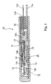
- battery protector 10 has a housing or casing 11 in the shape of a thin tube having one closed end.
- Casing 11 has an inner space or cavity 11 a where the functional members of the battery protector are disposed.
- a sealing member 12 is provided, as by pouring, in its opening 11 b, thereby sealing the functional members within the casing.
- the material for casing 10 is selected to electrically isolate the internal components from outside and, at the same time, to conduct heat from the ambient as much as possible.
- nylon resin can be employed.
- Battery protector 10 has a pair of leads 13 and 14 inside casing 11.
- One of the leads, lead 13, on the fixed side supports stationary or fixed contact 15 at one end within casing 11 and terminal 13a at the other end which extends out of casing 11.
- the other lead, lead 14, on the movable side supports movable contact 16 toward one end within casing 11 and terminal 14a at the other end which extends out of casing 11.
- terminals 13a and 14a of each of the leads are respectively connected between the electrode of the battery and the electrical product to be protected, thereby forming a closed circuit.
- stationary contact 15 is fixed such as by staking, etc., inside an opening 13b formed in the fixed-side lead 13 and is supported thereby.
- thermostat plate 20 and lead 14 on the movable side are each provided with an aperture in which is fitted an engaging protrusion 18a formed on resin block 18, protrusion 18a and the apertures preferably having a non-circular portion to provide a selected angular orientation.
- a holding plate 17, also having an aperture, is inserted on top of lead 14 and thermostat plate 20. The top of engaging protrusion 18a is then deformed either by heat or ultrasonic energy so as to make the several parts effectively integral with one another.
- the portion of lead 14 extending from the position fixed by the engaging protrusion 18a to the end portion where the movable contact 16 is provided (which will hereafter be referred to as the tip side) is left basically free.
- the tip side, or free movable portion, of lead 14 is bent approximately in the shape of an elbow or a hill and, as shown in Fig. 1, the apex or bent point 14b is caused to hit upper holding plate 17 in the state where movable contact 16 is in engagement with stationary contact 15.
- Lead 14 is an electrically conductive member formed of material capable of elastic deformation, such as beryllium copper. Because of the characteristics of the member, when thermostat plate 20, made of thermostat material, bends upwardly and pushes the convex dimple part 14c formed on lead 14 on the movable side upwardly, the tip side of lead 14 is elevated. It should be noted that thermostat plate 20 can be formed into a dished shape to make it snap-acting or, if desired, it can be formed without a dished shape to make it creep acting. As used in the following description, plate 20 will be referred to as snap-acting plate 20, and therefore provided with a dished shape.
- snap-acting plate 20 As described above, one end of snap-acting plate 20 is fixed, together with lead 14, by engagement protrusion 18a of block 18 deformed over plate 17. At normal times or when it is not in use, snap-acting plate 20 is slightly downwardly bent as shown in Fig. 1. The remainder of block 18 is positioned under snap-acting plate 20 and the distance snap-acting plate 20 can move from lead 14 on the movable side at normal times is limited by resin block 18.
- plate 20 is formed by using thermostat material, such as a bimetal, by bonding two or more layers of metals having different thermal coefficients of expansion and is so designed as to snap from the Fig. 1 configuration to the Fig. 3 configuration when the ambient temperature exceeds a prescribed temperature.
- thermostat material such as a bimetal
- the tip of the snap-acting plate 20 hits dimple 14c, with a result that lead 14 on the movable side is pushed upwardly separating movable contact 16 from stationary contact 15.
- the temperature elevation of snap-acting plate 20 reflects the temperature elevation of the ambient temperature of battery protector 10 and/or the heat generated by lead 14 on the movable side. Accordingly, in connection with heat generation by the battery that has been conducted or an excess electric current from the battery, snap-acting plate 20 is actuated, with a result that the power supply circuit is opened as shown in Fig. 3.
- holding plate 17 is made of a metal in the preferred embodiment and it is disposed between lead 14 on the movable side and casing 11.
- casing 11 which is preferably made of resin, is protected from being adversely affected by the heat.
- movable contact 16 in the preferred embodiment will be explained in detail.
- Figs. 4 and 5 are cross sectional views taken along lines A-A and B-B respectively in Fig. 2 and are cross sections of the movable contact.
- movable contact 16 is composed of a metal contact layer 41 on the side of the contact facing stationary contact 15, and a base metal layer 42 on the side where lead 14 on the movable side is fixed plus an insulating fiber layer 43 interposed between layers 41, 42.
- Movable contact 16 is desirably a clad member formed by mutually hot-pressing contact layer 41 and base material layer 42 to sandwich insulating layer 43. Movable contact 16, formed in this manner, is fixed by staking the periphery on the side of base material layer 42 in opening 14d of the lead on the movable side. In other words, it is formed so that lead 14 on the movable side and the material layer 42 side of the movable contact 16 are directly conductive. Electrical conductance between base material layer 42 and contact layer 41 is effected on both sides of the insulating layer 43 in the direction of the longitudinal axis of lead 14 as shown in Fig. 4, i.e., that part where the base material layer 42 and the contact layer 41 directly contact each other.
- the base material layer prefferably be formed with silver (Ag) and for contact layer 41 to be formed with an alloy of silver (Ag) and nickel (Ni) alloyed at the ratio of approximately 90:10).
- the thickness (dimension h in Fig. 5) of contact layer 41 can be selected in accordance with the desired estimated number of cycles as stipulated for the battery protector as a product. In other words, contact layer 41 is gradually consumed and reduced in thickness by electric arc discharges produced upon openings and closings of the contacts. Arcing occurs due to electric current that is impressed from the connected battery to the contact and causes the contact surface of contact layer 41 to evaporate.
- contact layer 41 Due to repetition of openings and closings of the contacts, contact layer 41 is gradually eroded off the contact surface, with insulating layer 43 finally being exposed. An approximate selected number of contact opening and closing cycles before insulating layer 43 becomes exposed can be obtained by selecting an appropriate thickness of contact layer 41.
- Insulating layer 43 composed of insulating fiber, becomes operative when contact layer 41 is almost completely consumed and the insulating fiber is exposed for the first time. As contact layer 41 is gradually consumed by electric arc discharges generated each time opening and closing of the contacts occur, insulating layer 43 is finally exposed on the side facing stationary contact 15 and stationary contact 15 then engages the surface of insulating layer 43 in its closed state.
- Fig. 6 shows the normal state of engagement between movable contact 16 and stationary contact 15 and, after the wearing of contact layer 41
- Fig. 7 shows the state in which contact layer 41 of movable contact 16 has been consumed and, at the same time, shows the state in which the contact surface 44 of the stationary contact 15 is likewise being consumed.
- the state in which the contact layer 41 has approximately completely been consumed indicates the final state of battery protector 10 or the final failure mode.
- the conductive parts of movable contact 16 become completely non-conductive. As a consequence of this, non-conductivity as the final failure mode of the battery protector 10 is assured.
- the insulating fiber that comprises insulating layer 43 in this invention is preferably glass fiber.
- a plurality of single yarns obtained by giving one directional twisting to the strands that have been made fibrous by several ⁇ m can be used as the base material for insulating layer 43.
- the glass fiber prior to the compressive adhesion of said contact layer 41 and the base material layer 42 has a cross section which is approximately circular; however, the fiber is crushed by the compression of the layers and becomes a layer having a prescribed width and thickness.
- Micro-Glass Yarn YECG 75 1/3 (a product of Nippon Sheet Glass Company, Limited) was used as glass fiber constituting said insulating layer 43 in making contacts according to the invention.
- Movable contact 16 made as described above can be prepared by hot-pressing layers of the metals to sandwich the glass fiber, followed by cutting into blocks. The preparation of the contacts by this method is extremely productive and provides a fixed yield. Insulating layer 43 made of fibers has a high level of pliability with a result that no great differences in the thickness of the contact layer 41 are produced. Because of this, it becomes possible to predict the number of stable cycles until the contact becomes non-conductive.
- the forms of implementation of this invention have been explained above. It is obvious that the range of applicability of this invention is not restricted to those items which have been shown in the above examples.
- the arrangements of the insulating layer inside the contact are not limited to those shown in the above examples. Any arrangement of the insulating layer can be used, provided that the stationary contact can engage the insulating layer when the contact layer is worn and the insulating layer has been exposed. In such case, it is desirable to determine the arrangement of the insulating layer in due consideration of the surface direction at the opening and closing of both contacts.
- the mutual contact surfaces In an arrangement where the movable contact moves along a curved path, the mutual contact surfaces generally slide against each other upon engagement or disengagement vis-à-vis the stationary contact, generally in a direction along the longitudinal axis of the movable portion of lead 14. Accordingly, it is desirable to arrange the insulating layer in due consideration of such movement. For example, the accurate functioning of the insulating layer is assured by arranging the insulating fiber in a direction which crosses the longitudinal axis of the movable portion of lead 14, in the arrangement of the example at 90 degrees.
- a clad member with an insulating fiber is provided in the movable contact.
- the insulating fiber may be provided in the stationary contact or in both of the contacts.
- This invention can be used widely not only for battery protectors as noted but also for various electrical apparatus whose main function lies in opening and closing contacts by a variation in the environment, for example, motor protectors, thermostats, pressure switches, circuit breakers, relays, and the like.
- the non-conductivity of the final failure mode in the electrical apparatus having contacts that are opened or closed by a physical change is provided thereby improving the reliability of the apparatus.
- the desired number of cycles of the electrical apparatus is assured.
Landscapes
- Thermally Actuated Switches (AREA)
- Contacts (AREA)
- Switch Cases, Indication, And Locking (AREA)
- Coupling Device And Connection With Printed Circuit (AREA)
Abstract
Description
Claims (17)
- An electrical contact for opening or closing an electric circuit comprising a first layer of electrically conductive material of a prescribed thickness that includes a contact surface, a second layer of electrically conductive material for connection to the electric circuit, and an insulating layer that is interposed between the first layer and second layers, whereby wearing away of the first layer eventually exposes the insulating layer.
- An electrical contact according to claim 1, wherein the first layer is composed of a material whose main ingredients are silver (Ag) and nickel (Ni) and the second layer is composed of a material whose main ingredient is silver (Ag).
- An electrical contact according to claim 1 or claim 2, wherein the insulating layer comprises insulating fiber.
- An electrical contact according to claim 3, wherein said insulating fiber is glass fiber.
- An electrical contact according to any preceding claim, wherein said first and second layers are in electrical contact with each other.
- An electrical apparatus comprising a casing, first and second terminals which are electrically separated extending from without the casing into the casing, a first contact which is electrically connected to the first terminal within the casing, a second contact which is electrically connected to the second terminal within the casing, and an operating member which electrically connects and disconnects said first and second terminals by relatively connecting and disconnecting said first and second contacts, the first and second contacts each having a contact surface, the contacts being movable relative to one another, at least the said first contact being a contact according to any preceding claim the contact surface of which engaging the contact surface of the second contact when the first and second contacts are connected, and the second layer of which being connected to the first terminal within the housing, the second contact effecting engagement with the electrically insulating layer when the insulating layer has been exposed due to wear of said first layer in response to engaging and disengaging movement of the first and second contacts.
- An electrical apparatus according to any preceding claim, wherein said first contact is a movable contact and said second contact is a stationary contact.
- An electrical apparatus according to claim 7, wherein the operating means moves the first contact in such a fashion that the contact surface of the first contact and the contact surface of the second contact slidingly engage each other.
- An electrical apparatus according to any of claims 6 to 8, wherein the insulating layer is disposed in alignment with a location of the contact surfaces which slidingly engage each other.
- An electrical apparatus according to claim 9, in which the contacts slidingly engage each other in a selected first direction and the insulating layer extends generally in a second direction generally ninety degrees relative to the first direction.
- An electrical apparatus according to any one of claims 7 to 10, wherein the operating member is mechanically displaced in response to selected variations in the ambient temperature, with movement of the first contact being actuated by the mechanical displacement of said member.
- An electrical apparatus according to any one of claims 7 to 11, wherein said operating member is mechanically displaced in response to a selected change in electric current passing through the apparatus, with movement of the first contact being actuated by the mechanical displacement of the member.
- An electrical apparatus according to any one of claims 7 to 12, wherein said operating member is mechanically displaced in response to a selected variation in pressure, with movement of the first contact being actuated by the mechanical displacement of the member.
- A pair of electrical contacts comprising a first electrical contact according to any one of claims 1 to 5 and a second electrical contact, the said contact surface of the first electrical contact being movable into and out of engagement with the second contact, wherein the insulating layer of the first contact so engages the second contact, when the contacts move together and the first layer has been exposed due to wearing of the first layer of the first contact in response to the closing and opening of the contact pair, as to prevent conduction between the first and second contacts.
- An electrical circuit comprising an electrical contact or an electrical apparatus or a pair of electrical contacts as claimed in any preceding claim wherein the contact is or the first and second contacts are so connected in the electrical circuit as to open and close that circuit.
- A method of making an electrical contact or an electrical apparatus or an electrical circuit according to any preceding claim comprising the step of hot-pressing the first and second layers of electrically conductive material to sandwich the insulating layer.
- A method of making an electrical contact or electrical apparatus or an electrical circuit according to claim 16 comprising the step of cutting the sandwich of the first and second and insulating layers into blocks.
Applications Claiming Priority (2)
| Application Number | Priority Date | Filing Date | Title |
|---|---|---|---|
| JP12195099 | 1999-04-28 | ||
| JP11121950A JP2000311574A (en) | 1999-04-28 | 1999-04-28 | Electrical equipment |
Publications (2)
| Publication Number | Publication Date |
|---|---|
| EP1049118A2 true EP1049118A2 (en) | 2000-11-02 |
| EP1049118A3 EP1049118A3 (en) | 2002-07-10 |
Family
ID=14823942
Family Applications (1)
| Application Number | Title | Priority Date | Filing Date |
|---|---|---|---|
| EP00303629A Withdrawn EP1049118A3 (en) | 1999-04-28 | 2000-04-28 | Electrical apparatus having improved electrical contact and electrical contact used therewith |
Country Status (4)
| Country | Link |
|---|---|
| US (1) | US6281780B1 (en) |
| EP (1) | EP1049118A3 (en) |
| JP (1) | JP2000311574A (en) |
| KR (1) | KR20000071862A (en) |
Cited By (4)
| Publication number | Priority date | Publication date | Assignee | Title |
|---|---|---|---|---|
| WO2015106975A1 (en) * | 2014-01-16 | 2015-07-23 | Robert Bosch Gmbh | Switching device for switching high electric currents, and battery system comprising such a switching device |
| CN105304357A (en) * | 2015-09-15 | 2016-02-03 | 中国北车集团大连机车车辆有限公司 | Layered composite contacts |
| CN106206088A (en) * | 2016-08-30 | 2016-12-07 | 南通万德科技有限公司 | A kind of electric contact and manufacture method thereof |
| DE112007000674B4 (en) | 2006-03-24 | 2023-06-07 | Uchiya Thermostat Co., Ltd. | COATED CONTACT POINT MATERIAL, CONTACT POINT OBJECT AND CONTACT POINT OBJECT ATTACHING METHOD |
Families Citing this family (19)
| Publication number | Priority date | Publication date | Assignee | Title |
|---|---|---|---|---|
| US6559752B1 (en) * | 1999-05-24 | 2003-05-06 | Frank J. Sienkiewicz | Creepless snap acting bimetallic switch having flexible contact members |
| JP3787482B2 (en) * | 2000-04-17 | 2006-06-21 | ウチヤ・サーモスタット株式会社 | Thermal protector |
| JP4338332B2 (en) * | 2001-03-02 | 2009-10-07 | ウチヤ・サーモスタット株式会社 | Thermal protector |
| JP4424870B2 (en) * | 2001-03-19 | 2010-03-03 | 株式会社センサータ・テクノロジーズジャパン | Protector |
| US6771159B2 (en) * | 2001-11-08 | 2004-08-03 | Airpax Corporation L.L.C. | Contact spring for miniature thermostat |
| CN1428806A (en) * | 2001-12-07 | 2003-07-09 | 古河电气工业株式会社 | Thermal protector |
| JP3828476B2 (en) * | 2002-10-15 | 2006-10-04 | 株式会社センサータ・テクノロジーズジャパン | Non-energized sealed motor protector |
| WO2008053575A1 (en) * | 2006-10-30 | 2008-05-08 | Uchiya Thermostat Co., Ltd. | Thermal protector |
| US7355139B1 (en) * | 2007-04-26 | 2008-04-08 | Tsung-Mou Yu | Miniature circuit breaker |
| US8717729B2 (en) * | 2008-02-12 | 2014-05-06 | Hewlett-Packard Development Company, L.P. | Computing devices having fail-safe mechanical shut-off switch |
| DE102008048554B3 (en) * | 2008-09-16 | 2010-02-04 | Hofsaess, Marcel P. | Temperature-dependent switch |
| US9000880B2 (en) * | 2009-03-12 | 2015-04-07 | Uchiya Thermostat Co., Ltd. | Thermal protector |
| US9472363B2 (en) | 2009-03-12 | 2016-10-18 | Uchiya Thermostat Co., Ltd. | Thermal protector |
| CN102341878B (en) * | 2009-03-12 | 2014-02-12 | 打矢恒温器株式会社 | Thermal switch |
| CN102598183B (en) | 2009-11-04 | 2014-07-23 | 打矢恒温器株式会社 | A circuit to which a thermal switch with three terminals is connected and its connection method |
| TWI415155B (en) | 2010-09-13 | 2013-11-11 | Powertech Ind Co Ltd | Protection circuit |
| CN102412094B (en) * | 2010-09-20 | 2014-12-31 | 胜德国际研发股份有限公司 | Protective circuit |
| CN102593633B (en) * | 2011-01-10 | 2014-08-20 | 胜德国际研发股份有限公司 | Socket device with replaceable protection module |
| US9159985B2 (en) * | 2011-05-27 | 2015-10-13 | Ostuka Techno Corporation | Circuit breaker and battery pack including the same |
Family Cites Families (8)
| Publication number | Priority date | Publication date | Assignee | Title |
|---|---|---|---|---|
| US3114812A (en) * | 1962-06-12 | 1963-12-17 | American Thermostat Corp | Dual action thermostat having plural adjustment means |
| SE419806B (en) * | 1973-08-30 | 1981-08-24 | Ego Elektro Blanc & Fischer | ELECTRICAL SWITCH |
| US5036379A (en) * | 1986-10-11 | 1991-07-30 | Microelectronics And Computer Technology Corporation | Electrical interconnect tape |
| DE3714802A1 (en) * | 1987-05-04 | 1988-11-17 | Siemens Ag | ELECTRIC SWITCH |
| JP3241139B2 (en) * | 1993-02-04 | 2001-12-25 | 三菱電機株式会社 | Film carrier signal transmission line |
| US5489762A (en) * | 1994-05-25 | 1996-02-06 | Texas Instruments Incorporated | Appliances having resistive heating elements and thermal protective apparatus used therewith |
| US5844331A (en) * | 1994-10-27 | 1998-12-01 | Siemens Aktiengesellschaft | Process for monitoring the wear of at least one contact in a switching device and switching device designed thereof |
| JP2895793B2 (en) * | 1995-02-24 | 1999-05-24 | マブチモーター株式会社 | Sliding contact material, clad composite material, commutator made of the same, and small DC motor using the commutator |
-
1999
- 1999-04-28 JP JP11121950A patent/JP2000311574A/en active Pending
-
2000
- 2000-04-26 US US09/558,823 patent/US6281780B1/en not_active Expired - Fee Related
- 2000-04-28 EP EP00303629A patent/EP1049118A3/en not_active Withdrawn
- 2000-04-28 KR KR1020000022854A patent/KR20000071862A/en not_active Withdrawn
Cited By (7)
| Publication number | Priority date | Publication date | Assignee | Title |
|---|---|---|---|---|
| DE112007000674B4 (en) | 2006-03-24 | 2023-06-07 | Uchiya Thermostat Co., Ltd. | COATED CONTACT POINT MATERIAL, CONTACT POINT OBJECT AND CONTACT POINT OBJECT ATTACHING METHOD |
| WO2015106975A1 (en) * | 2014-01-16 | 2015-07-23 | Robert Bosch Gmbh | Switching device for switching high electric currents, and battery system comprising such a switching device |
| CN105900201A (en) * | 2014-01-16 | 2016-08-24 | 罗伯特·博世有限公司 | Switchgear for switching large currents and battery system with such a switchgear |
| KR20160107180A (en) * | 2014-01-16 | 2016-09-13 | 로베르트 보쉬 게엠베하 | Switching device for switching high electric currents, and battery system comprising such a switching device |
| CN105900201B (en) * | 2014-01-16 | 2019-01-15 | 罗伯特·博世有限公司 | For switching the switching device of high current and the battery system with this switching device |
| CN105304357A (en) * | 2015-09-15 | 2016-02-03 | 中国北车集团大连机车车辆有限公司 | Layered composite contacts |
| CN106206088A (en) * | 2016-08-30 | 2016-12-07 | 南通万德科技有限公司 | A kind of electric contact and manufacture method thereof |
Also Published As
| Publication number | Publication date |
|---|---|
| US6281780B1 (en) | 2001-08-28 |
| JP2000311574A (en) | 2000-11-07 |
| KR20000071862A (en) | 2000-11-25 |
| EP1049118A3 (en) | 2002-07-10 |
Similar Documents
| Publication | Publication Date | Title |
|---|---|---|
| US6281780B1 (en) | Electrical apparatus having improved electrical contact and electrical contact used therewith | |
| US5804798A (en) | Thermal protector with bimetal plate | |
| US7075403B2 (en) | Motor protector particularly useful with hermetic electromotive compressors | |
| US5844464A (en) | Thermal switch | |
| EP3751589A1 (en) | Temperature controller with thermal protection | |
| WO2013094725A1 (en) | Breaker, and safety circuit and secondary battery pack equipped with same | |
| JP6997685B2 (en) | Current breaker, safety circuit and rechargeable battery pack | |
| WO1992019002A1 (en) | Over-current/over-temperature protection device | |
| EP0714550B1 (en) | Electric switches | |
| US7071809B2 (en) | Thermal fuse containing bimetallic sensing element | |
| CN119764129A (en) | Protection element for anti-impact circuit | |
| KR20030047801A (en) | Thermal protector | |
| JP6592299B2 (en) | Breaker, safety circuit including the same, and secondary battery circuit. | |
| US5014034A (en) | Thermostatic switch with insulated calibration dimple | |
| KR100573545B1 (en) | Thermodynamic switch | |
| JP3257680B2 (en) | Thermal response switch and method of manufacturing the same | |
| CA1328985C (en) | Method of forming a thermostatic switch with a narrow operating temperature range | |
| GB2373926A (en) | Thermal sensor | |
| US3833873A (en) | Thermal protector | |
| JP6997687B2 (en) | Breaker and safety circuit | |
| JP3632754B2 (en) | Battery breaker | |
| JP6085107B2 (en) | Breaker, safety circuit including the same, and secondary battery circuit | |
| WO2008127028A1 (en) | Apparatus for blocking overheat by using shape memory alloy | |
| JPH0547278A (en) | Heat-responsive switch | |
| CN206163417U (en) | Protector and electrical equipment that can install protector |
Legal Events
| Date | Code | Title | Description |
|---|---|---|---|
| PUAI | Public reference made under article 153(3) epc to a published international application that has entered the european phase |
Free format text: ORIGINAL CODE: 0009012 |
|
| AK | Designated contracting states |
Kind code of ref document: A2 Designated state(s): AT BE CH CY DE DK ES FI FR GB GR IE IT LI LU MC NL PT SE |
|
| AX | Request for extension of the european patent |
Free format text: AL;LT;LV;MK;RO;SI |
|
| PUAL | Search report despatched |
Free format text: ORIGINAL CODE: 0009013 |
|
| AK | Designated contracting states |
Kind code of ref document: A3 Designated state(s): AT BE CH CY DE DK ES FI FR GB GR IE IT LI LU MC NL PT SE |
|
| AX | Request for extension of the european patent |
Free format text: AL;LT;LV;MK;RO;SI |
|
| RIC1 | Information provided on ipc code assigned before grant |
Free format text: 7H 01H 1/50 A, 7H 01H 1/00 B |
|
| AKX | Designation fees paid | ||
| REG | Reference to a national code |
Ref country code: DE Ref legal event code: 8566 |
|
| STAA | Information on the status of an ep patent application or granted ep patent |
Free format text: STATUS: THE APPLICATION IS DEEMED TO BE WITHDRAWN |
|
| 18D | Application deemed to be withdrawn |
Effective date: 20030111 |