EP1049081A2 - Disc drive unit - Google Patents
Disc drive unit Download PDFInfo
- Publication number
- EP1049081A2 EP1049081A2 EP00109231A EP00109231A EP1049081A2 EP 1049081 A2 EP1049081 A2 EP 1049081A2 EP 00109231 A EP00109231 A EP 00109231A EP 00109231 A EP00109231 A EP 00109231A EP 1049081 A2 EP1049081 A2 EP 1049081A2
- Authority
- EP
- European Patent Office
- Prior art keywords
- light
- disk
- signal
- reflected light
- output
- Prior art date
- Legal status (The legal status is an assumption and is not a legal conclusion. Google has not performed a legal analysis and makes no representation as to the accuracy of the status listed.)
- Withdrawn
Links
Images



Classifications
-
- G—PHYSICS
- G11—INFORMATION STORAGE
- G11B—INFORMATION STORAGE BASED ON RELATIVE MOVEMENT BETWEEN RECORD CARRIER AND TRANSDUCER
- G11B7/00—Recording or reproducing by optical means, e.g. recording using a thermal beam of optical radiation by modifying optical properties or the physical structure, reproducing using an optical beam at lower power by sensing optical properties; Record carriers therefor
- G11B7/12—Heads, e.g. forming of the optical beam spot or modulation of the optical beam
- G11B7/125—Optical beam sources therefor, e.g. laser control circuitry specially adapted for optical storage devices; Modulators, e.g. means for controlling the size or intensity of optical spots or optical traces
- G11B7/126—Circuits, methods or arrangements for laser control or stabilisation
-
- G—PHYSICS
- G11—INFORMATION STORAGE
- G11B—INFORMATION STORAGE BASED ON RELATIVE MOVEMENT BETWEEN RECORD CARRIER AND TRANSDUCER
- G11B7/00—Recording or reproducing by optical means, e.g. recording using a thermal beam of optical radiation by modifying optical properties or the physical structure, reproducing using an optical beam at lower power by sensing optical properties; Record carriers therefor
- G11B7/002—Recording, reproducing or erasing systems characterised by the shape or form of the carrier
- G11B7/0037—Recording, reproducing or erasing systems characterised by the shape or form of the carrier with discs
- G11B7/00375—Recording, reproducing or erasing systems characterised by the shape or form of the carrier with discs arrangements for detection of physical defects, e.g. of recording layer
-
- G—PHYSICS
- G11—INFORMATION STORAGE
- G11B—INFORMATION STORAGE BASED ON RELATIVE MOVEMENT BETWEEN RECORD CARRIER AND TRANSDUCER
- G11B7/00—Recording or reproducing by optical means, e.g. recording using a thermal beam of optical radiation by modifying optical properties or the physical structure, reproducing using an optical beam at lower power by sensing optical properties; Record carriers therefor
- G11B7/004—Recording, reproducing or erasing methods; Read, write or erase circuits therefor
- G11B7/0045—Recording
Definitions
- the present invention relates to a disk drive unit.
- optical disk recording media there have been developed a CD (compact disk) type disk and a disk called DVD (Digital versatile Disk/Digital Video Disk) suitably used for multi-media.
- a recording apparatus accommodating to those optical disks irradiates laser light modulated by recording data to tracks on the disk to record the data by a phase-change recording method for example.
- the normal recording condition has been obtained by detecting such detect for example based on the changes of the quantity of light reflected from the disk and by holding the servo signal or by stopping the recording operation once to retry for example based on the result of detection.
- the recording operation of a disk drive unit has been carried out by storing storage data supplied from an external equipment such as a host computer once in a buffer memory provided within the disk drive unit for example and by reading the recording data stored in the buffer memory. That is, when a number of times of retry increases, the frequency of reading recording data from the buffer memory drops. Accordingly, particularly when image data (video data) supplied continuously in correspondence to real time is to be recorded, an amount of data to be read out drops with respect to an amount of data read in, the storage area of the buffer memory saturates and some data may be lost. That is, there has been a problem that the number of times of retry increases and it may become difficult to carry out the recording operation stably as contaminant increases on the surface of the disk.
- a disk drive unit comprises head means for irradiating laser light to a loaded disk recording medium via an objective lens so as to at least recording data; objective lens driving mechanism for moving the objective lens in the direction of contacting/separating to/from the disk recording medium and in the radial direction of the disk recording medium based on certain control signals; reflected light quantity detecting means for detecting a quantity of reflected light of beam irradiated to the disk recording medium; light quantity reduction speed discriminating means for discriminating whether the reduction speed of the quantity of light detected by the reflected light quantity detecting means is faster than a certain time constant or not; and laser light output control means for controlling an output level of the laser light based on the discrimination result of the light quantity reduction speed discriminating means.
- a disk drive unit also comprises head means for irradiating laser light to a loaded disk recording medium via an objective lens so as to at least recording data; output light quantity detecting means for detecting a quantity at output light of laser light outputted from the objective lens; reflected light quantity detecting means for detecting a quantity of reflected light of beam irradiated to the disk recording medium; and output light quantity control means for controlling an output level of the quantity of output light so that a product of the quantity of output light and the quantity of reflected light becomes a predetermined value.
- the invention allows the cause of changes of a quantity of reflected light to be discriminated based on speed of the changes of quantity of reflected light from the disk recording medium. It then allows a required control corresponding to the change of quantity of reflected light to be made.
- An optical disk loaded into the disk drive unit of this example may be a CD type disk such as CD-R and a disk called DVD (Digital Versatile Disc/Digital Video Disc).
- the present invention is also applicable to a disk drive unit accommodating other types of optical disks.
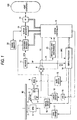
- FIG. 1 is a block diagram of the main part of the exemplary disk drive unit. This disk drive unit implements data recording/reproducing operation corresponding to a request from a connected host computer 100.
- a disk 90 is a DVD type disk or a CD type disk such as CD-R and CD-ROM for example.
- the disk 90 is mounted on a turn table 7 and is rotated at constant line velocity (CLV) or constant angle velocity (CAV) by a pickup 1 in recording/reproducing data.
- CLV constant line velocity
- CAV constant angle velocity
- the pickup 1 reads data recorded in the disk 90 in emboss pit mode or phase change pit (mark) mode or records/erases data as phase change pits (mark).
- a laser diode 4 which is a laser light source, a photo-detector 5 for detecting reflected light, an objective lens 2 which is an output end of the laser light and an optical system for irradiating the laser light to the disk recording plane via the objective lens 2 and for guiding the reflected light to the photo-detector 5.
- the objective lens 2 is held movably in the tracking and focusing directions by a biaxial mechanism 3.
- the whole pickup 1 is also held movably in the disk radial direction by a sledding mechanism 8.
- the photo-detector 5 detects information of reflected light from the disk 90 which can be obtained by irradiating laser light in reproducing/recording data and supplies it to an RF amplifier 9 as an electrical signal corresponding to a quantity of received light.
- the RF amplifier 9 comprises a current-voltage converting circuit, a matrix calculation/amplifier circuit and others in correspondence to output currents from a plurality of light receiving elements as the photo-detector 5 to generate required signals by a matrix calculating process. For instance, it generates an RF signal which is a reproduced data, a focus error signal FE for servo control, a tracking error signal TE or a pull-in signal PI which is a sum signal of reflected light.
- the RF signal outputted from the RE amplifier 9 is supplied to a binarizing circuit 11 while the focus error signal FE and the tracking error signal TE are supplied to a servo processor 14.
- a reflected light discriminating section 23 is arranged so as to be able to discriminate contaminant (dust, scratch, etc.) on the surface of the disk or defects of the recording plane based on speed of change of the level of the pull-in signal PI as described later in detail and supplies a discrimination signal to a system controller 10.
- the RF signal obtained by the RF amplifier 9 is transformed into a so-called EFM signal (8-14 modulation signal: in case of CD type disk) or an EFM + signal (8-16 modulation signal: in case of DVD type disk) by being binarized by the binarizing circuit 11 and is supplied to an encoder/decoder 12.
- the encoder/decoder 12 implements EFM demodulating and error correcting processes or CD-ROM decoding and MPEG decoding processes as necessary to reproduce the information read from the disk 90.
- the data decoded by the encoder/decoder 12 is stored in a cache memory 20 by the operation of a buffer manager 21 for implementing processes of writing/reading to/from the cache memory 20. That is, a so-called buffering operation is carried out.
- the data buffered in the cache memory 20 is transferred and outputted as the reproduced output from the reproducing unit.
- the data from the cache memory 20 is transferred and outputted under the control of the system controller 10 (control as firmware).
- An interface section 13 is connected with the external host computer 100 to transmit reproduced data and to communicate read commands between the host computer 100.
- the reproduced data stored in the cache memory 20 is transferred and outputted to the host computer 100 via the interface section 13.
- the read command and other signals from the host computer 100 are supplied to the system controller 10 via the interface section 13.
- the servo processor 14 generates various servo drive signals of focusing, tracking, sled and spindle from the focus error signal FE and the tracking error signal TE from the RF amplifier 9 and a spindle error signal SPE from the encoder/decoder 12 or the system controller 10 to execute the servo operation.
- the biaxial driver 16 drives focusing and tracking coils of the biaxial mechanism 3 in the pickup 1.
- a tracking servo loop and a focus servo loop are formed by the pickup 1, the RF amplifier 9, the servo processor 14, the biaxial driver 16 and the biaxial mechanism 3.
- the point where the focus error signal FE is zeroed and the point where information may be reproduced most efficiently from the disk 90 must be the same ideally, actually those points deviate from each other.
- This deviation will be called as focusing bias and the servo system is controlled so that the focusing state is converged to the point where the amplitude of the reproduced RF signal is maximized by arranging it so as to add bias voltage corresponding to the focus bias to the focus error signal FE.
- Tracking bias also exists in the tracking error signal TE.
- the servo processor 14 also supplies a spindle drive signal generated corresponding to the spindle error signal SPE to a spindle motor driver 17.
- the spindle motor driver 17 applies a three-phase drive signal for example to a spindle motor 6 to execute CLV rotation of the spindle motor 6.
- the servo processor 14 also generates the spindle drive signal corresponding to a spindle kick/brake control signal from the system controller 10 to cause the spindle motor driver 17 to execute the operations of the spindle motor 6 such as start and stop.
- the servo processor 14 generates a sled error signal obtained as a low range component of the tracking error signal TE and a sled drive signal based on the control of execution of accesses and the like from the system controller 10 to supply to a sled driver 15.
- the sled driver 15 drives a sledding mechanism 8.
- the sledding mechanism 8 has a mechanism comprising a main shaft for holding the pickup 1, a sled motor, a transmission gear and the like. The pickup 1 is slidably moved as necessary as the sled driver 15 drives the sled motor 8 corresponding to the sled drive signal.
- a laser driver 18 drives the laser diode 4 in the pickup 1 so as to irradiate laser light.
- the system controller 10 sets values of control of the laser power in an automatic power control circuit (hereinafter referred to as an APC circuit) 19 and the APC circuit 19 controls the laser driver 18 so as to output laser corresponding to the values of the laser power.
- an APC circuit automatic power control circuit
- signals modulated corresponding to recording data are applied to the laser driver 18.
- recording data supplied from the host computer 100 to the interface section 13 is supplied to the laser driver 18 after undergoing the processes of addition of error correcting codes, EFM + modulation, NRZI modulation and others executed by the encoder/decoder 12.
- the recording of data to the disk 90 is executed when the laser driver 18 causes the laser diode 4 to irradiate laser light corresponding to the recording data.
- the system controller 10 formed of a micro-computer controls the various operations such as servo, decoding and encoding as described above.
- the system controller 10 issues a command to the servo processor 14 as an operation for reading a required data section corresponding to a read command from the host computer 100 and causes the pickup 1 to execute an accessing operation by targeting at the starting position of the data section required to transfer by the read command. Then, after ending the access, the system controller 10 causes the servo processor 14 to execute the reading of data, causes the encoder/decoder 12 and the cache memory 20 to execute required processes and controls so as to transfer the reproduced data (required data) from the interface section 13 to the host computer 100.
- the system controller 10 issues a command to the servo processor 14 as an operation for writing supplied data corresponding to a write command from the host computer 100 to cause the pickup 1 to execute an operation for accessing to the writing start position. Then, after ending the access, the system controller 10 causes the cache memory 20, the encoder/decoder 12, the laser driver 18 and others to execute required processes to record the recording data (supplied data) to the disk 90.
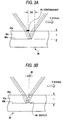
- FIG. 2 is a diagrammatic view for explaining the relationship of size of illumination area of a beam outputted from the objective lens 2 on the surface and the recording plane of the disk 90. It is noted that this figure is a plan view and the area where the beam is irradiated is illustrated by its diameter.
- an numerical aperture NA (sin ⁇ ) of the objective lens 2 is denoted as NAo
- the refractive index of a disk substrate 90c as nl
- a thickness from the surface 90a to the recording plane 90b of the disk as t
- linear velocity when the disk 90 rotates V.
- the diameter Ds of the illumination area of the beam at the surface 90a of the disk may be expressed as follows:
- the change of the quantity of reflected light appears in the level reduction time of the pull-in signal PI and may be expressed as: ts > tf
- defect 96 shown in the recording plane 90b in FIG. 3b is diagrammatically shown to explain its position and size.
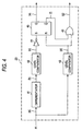
- FIG. 4 is a block diagram for explaining a structural example of the reflected light discriminating section 23 for discriminating the contaminant 95 from the defect 96 based on the pull-in signal PI outputted from the RF amplifier 9. It is noted that waveforms of signals at the regions denoted by (a) through (g) correspond respectively to signals in FIGs. 5A through 5G, respectively.
- the pull-in signal PI in FIG. 5A shows the condition influenced by the defect 96 and the contaminant 95 for example and its level is changed corresponding to the time ts or the time tf as described before.
- Such pull-in signal PI in FIG. 5A is supplied to a differentiator 41 having a certain time constant and then supplied to a level comparator 42 as a differential signal in FIG. 5B within the reflected light discriminating section 23.
- This differentiator 41 is formed by having the time constant almost at the intermediate point of the time tf and the time ts.
- the level comparator 42 binarizes the differential signal in FIG. 5B by a certain reference value ref and outputs a binary signal in FIG. 5C. That is, because the time constant almost at the intermediate point of the time tf and the time ts is set in the differentiator 41, the binary signal in FIG. 5C is a signal corresponding to the level relatively quickly reducing.
- a level comparator 43 binarizes the pull-in signal PI in FIG. 5A by a certain reference value ref and outputs a binary signal in FIG. 5D.
- This binary signal in FIG. 5D is an output corresponding to the change of level of the pull-in signal PI in FIG. 5A.
- the binary signal in FIG. 5C from the level comparator 42 is inverted by an inverter 44 and then supplied to a set terminal of an RS flip-flop 45.
- the binary signal in FIG. 5D from the level comparator 43 is supplied to a reset terminal of the RS flip-flop 45 as well as to an OR gate 46.
- the RS flip-flop 45 outputs a defect detecting signal in FIG. 5E corresponding to the change of level caused by the defect of the recording plane 90b in the pull-in signal PI in FIG. 5A by setting by the binary signal in FIG. 5C and by resetting by the binary signal in FIG. 5D. That is, the output signal in FIG. 5E is an output signal which turns to low level for example corresponding to the change of level caused by the defect of the recording plane 90b in the pull-in signal PI in FIG. 5A.
- the binary signal in FIG. 5D and an invertion signal in FIG. 5F of the RS flip-flop 45 are supplied to the OR gate 46 to output a logical sum of the respective signals. That is, the binary signal in FIG. 5D is masked by the inversion signal in FIG. 5F in the OR gate 46 to form a contaminant detecting signal in FIG. 5G.
- This contaminant detecting signal in FIG. 5G is an output signal which turns to low level corresponding to the change of level caused by the contaminant 95 on the disk surface 90a in the pull-in signal PI in FIG. 5A.
- the reflected light discriminating section 23 generates the defect detecting signal in FIG. 5E and the contaminant detecting signal in FIG. 5G as described above and supplies to the system controller 10.
- the system controller 10 controls the APC circuit 19 to increase a quantity of laser light outputted from the laser diode 4 to compensate the quantity of reflected light reduced due to the contaminant. It allows the quantity of light at the focal point on the recording plane 90b to be maintained at a predetermined level and the deterioration of the recording condition may be reduced.
- the system controller 10 drives the biaxial mechanism 3 while holding the focus drive signal and the tracking drive signal by assuming that the defect 96 is detected on the recording plane 90b. It enables to suppress the focus servo and the tracking servo from deviating due to the defect. It is noted that it is possible to drive the pickup 1 while holding the sled error signal in some cases.
- the system controller 10 retries the recording operation.
- the recording may be carried out continuously by increasing the quantity of laser light without retrying when the contaminant 95 is detected on the disk surface 90a. That is, it is possible to record stably while suppressing a number of times of retry even when data such as video image corresponding to real time is to be recorded to the disk 90 having much contaminant on the disk surface 90a.
- a stable recording operation may be realized also when the defect is detected continuously for a certain degree of time because the recording operation is retried in such case.
- the invention is also applicable in reproducing data. That is, when good reproduced signals cannot be obtained by being blocked by contaminant and the like, it is possible to maintain a quantity of laser light arriving at the recording plane by increasing a quantity of laser light from the laser diode 4.
- the power of the laser light outputted from the laser diode 4 is controlled by the control values of the APC circuit 19 set by the system controller 10 for example. Then, it is possible to obtain the predetermined output of laser light under the control of the APC circuit 19 even when a quantity of reflected light from the disk 90 decreases due to contaminant or the like and the difference of quantity of laser light outputted from the laser diode 4 becomes large.
- a photo-detector 50 for detecting the quantity of laser light outputted from the laser diode 4 and an optical system for guiding the laser light (output light) outputted from the laser diode 4 with respect to the photo-detector 50 are formed within the pickup 1 as shown in FIG. 6 for example. Then, a product of signals detected by the photo-detector 5 for detecting the laser light from the disk 90 and by the photo-detector 50 for detecting the quantity of output light from the laser diode 4 is calculated to control the APC circuit 19 based on the product.
- a detection signal D1 detected by the photo-detector 5 and passed through the RF amplifier 9 and a detection signal D2 detected by the photo-detector 50 and passed through an amplifier 51 are supplied to an integrator section 60 and an integration signal D3 integrated by the integrator section 60 is supplied to the system controller 10 for example.
- the system controller 10 sets the control value of the laser power at the APC circuit 19 as explained in FIG. 1, it sets a control value which allows a quantity of laser light to be obtained by which the integration signal D3 becomes a predetermined value here.
- a control value which increases laser light is set at the APC circuit 19 when a quantity of reflected light from the disk 90 decreases due to contaminant for example. That is, the system controller 10 can maintain the quantity of laser light arriving at the recording plane 90a by executing the control of the APC circuit 19 based on the integration signal D3.
- This example is also applicable in reproducing data. That is, it is possible to maintain a quantity of laser light arriving at the recording plane by increasing the quantity of laser light from the laser diode 4 when no good reproduced signal can be obtained as it is blocked by contaminant or the like.
Landscapes
- Physics & Mathematics (AREA)
- Optics & Photonics (AREA)
- Optical Recording Or Reproduction (AREA)
- Optical Head (AREA)
- Investigating Materials By The Use Of Optical Means Adapted For Particular Applications (AREA)
Abstract
Description

Claims (5)
- A disk drive unit, comprising:head means for irradiating laser light to a loaded disk recording medium via an objective lens so as to at least record data;objective lens driving mechanism for moving said objective lens in the direction of contacting/separating to/from said disk recording medium and in the radial direction of said disk recording medium based on certain control signals;reflected light quantity detecting means for detecting a quantity of reflected light of beam irradiated to said disk recording medium;light quantity reduction speed discriminating means for discriminating whether the reduction speed of the quantity of light detected by said reflected light quantity detecting means is faster than a predetermined value or not; andlaser light output control means for controlling an output level of said laser light based on the discrimination result of said light quantity reduction speed discriminating means.
- The disk drive unit according to Claim 1, wherein said laser light output control means controls so as to increase the output level of said laser light when the reduction speed of said quantity of light is slower than the predetermined value as a discrimination result of said light quantity reduction speed discriminating means.
- The disk drive unit according to Claim 1, further comprising objective lens control means for holding servo signals for controlling the operation of said objective lens when the reflected light quantity detecting means detects the reduction of the quantity of reflected light.
- The disk drive unit according to Claim 3, further comprising recording control means for retrying recording operations when the reduction of the quantity of reflected light continues for more than a predetermined time.
- A disk drive unit, comprising:head means for irradiating laser light to a loaded disk recording medium via an objective lens so as to at least record data;output light quantity detecting means for detecting a quantity of output light of laser light outputted from said objective lens;reflected light quantity detecting means for detecting a quantity of reflected light of beam irradiated to said disk recording medium; and
output light quantity control means for controlling an output level of said quantity of output light so that a product of said quantity of output light and said quantity of reflected light becomes a predetermined value.
Applications Claiming Priority (2)
| Application Number | Priority Date | Filing Date | Title |
|---|---|---|---|
| JP11122874A JP2000311373A (en) | 1999-04-28 | 1999-04-28 | Disk drive device |
| JP12287499 | 1999-04-28 |
Publications (2)
| Publication Number | Publication Date |
|---|---|
| EP1049081A2 true EP1049081A2 (en) | 2000-11-02 |
| EP1049081A3 EP1049081A3 (en) | 2003-03-19 |
Family
ID=14846774
Family Applications (1)
| Application Number | Title | Priority Date | Filing Date |
|---|---|---|---|
| EP00109231A Withdrawn EP1049081A3 (en) | 1999-04-28 | 2000-04-28 | Disc drive unit |
Country Status (8)
| Country | Link |
|---|---|
| US (1) | US6654329B1 (en) |
| EP (1) | EP1049081A3 (en) |
| JP (1) | JP2000311373A (en) |
| KR (1) | KR100733530B1 (en) |
| CN (1) | CN1147840C (en) |
| ID (1) | ID25700A (en) |
| MY (1) | MY125383A (en) |
| TW (1) | TW514889B (en) |
Cited By (4)
| Publication number | Priority date | Publication date | Assignee | Title |
|---|---|---|---|---|
| WO2003021584A1 (en) * | 2001-09-06 | 2003-03-13 | Koninklijke Philips Electronics N.V. | Method and device for running optimum power control |
| WO2008032941A1 (en) * | 2006-09-14 | 2008-03-20 | Samsung Electronics Co, . Ltd. | Method of processing defect detection signal in recording and/or reproducing apparatus that records and/or reproduces optical information storage medium |
| WO2008139406A1 (en) * | 2007-05-11 | 2008-11-20 | Koninklijke Philips Electronics N.V. | Method of recording over defects |
| EP1736969A4 (en) * | 2004-03-31 | 2009-02-04 | Pioneer Corp | Reader and disc deterioration detecting method |
Families Citing this family (6)
| Publication number | Priority date | Publication date | Assignee | Title |
|---|---|---|---|---|
| US6950378B1 (en) * | 1999-07-28 | 2005-09-27 | Matsushita Electric Industrial Co., Ltd. | Laser power control method and optical disk device |
| US6862088B2 (en) * | 2001-12-07 | 2005-03-01 | Zoran Corporation | Method and apparatus for providing adaptive control of track servo |
| US7054240B2 (en) * | 2002-03-04 | 2006-05-30 | Zoran Corporation | Method and apparatus for providing focus control on a multi layer disc |
| JP3931774B2 (en) * | 2002-09-20 | 2007-06-20 | 松下電器産業株式会社 | Defect detection device |
| US7301871B2 (en) * | 2004-03-03 | 2007-11-27 | Via Technologies, Inc | Method and device for detecting the signal on a disc having a defect by utilizing an RF signal and its derivatives |
| JP2007066484A (en) * | 2005-09-02 | 2007-03-15 | Matsushita Electric Ind Co Ltd | Optical disk apparatus control method and optical disk apparatus |
Family Cites Families (17)
| Publication number | Priority date | Publication date | Assignee | Title |
|---|---|---|---|---|
| JP2574765B2 (en) * | 1986-07-09 | 1997-01-22 | 株式会社日立製作所 | Magneto-optical disk device |
| JPS63188834A (en) * | 1987-01-30 | 1988-08-04 | Sony Corp | Laser luminous quantity control circuit for optical disk device |
| JP2926909B2 (en) | 1990-06-26 | 1999-07-28 | ソニー株式会社 | Disk drive device |
| US5184343A (en) | 1991-05-06 | 1993-02-02 | Johann Donald F | Compensation for dust on an optical disk by increasing laser writing power |
| JPH05234082A (en) * | 1992-02-21 | 1993-09-10 | Pioneer Electron Corp | Optical disk player |
| WO1994019800A1 (en) | 1993-02-22 | 1994-09-01 | Sony Corporation | Optical disc apparatus |
| JP3427410B2 (en) | 1993-02-24 | 2003-07-14 | ソニー株式会社 | Optical disk recording device and optical disk reproducing device |
| JPH06309610A (en) | 1993-04-28 | 1994-11-04 | Sony Corp | Magnetic head |
| JPH07272275A (en) | 1994-03-29 | 1995-10-20 | Sony Corp | Optical disk device |
| US5568461A (en) * | 1994-04-20 | 1996-10-22 | Matsushita Electric Industrial Co., Ltd. | Optical information recording and reproducing apparatus |
| KR970067153A (en) | 1996-03-13 | 1997-10-13 | 김광호 | How to control laser diodes in compact disk drives |
| JP3451834B2 (en) | 1996-04-23 | 2003-09-29 | ソニー株式会社 | Defect detection circuit and playback device |
| JP2000508812A (en) | 1997-01-29 | 2000-07-11 | コーニンクレッカ フィリップス エレクトロニクス エヌ ヴィ | Information recording / reproducing method and device |
| EP0969452A4 (en) * | 1997-03-25 | 2000-12-27 | Sanyo Electric Co | Information reproducer, information recorder and reference mark detection circuit |
| JPH10320809A (en) | 1997-05-16 | 1998-12-04 | Sony Corp | Disk drive device |
| KR100285315B1 (en) * | 1997-09-24 | 2001-04-02 | 구자홍 | Method and device for inspecting quality of optical disc |
| JP4036515B2 (en) * | 1997-12-22 | 2008-01-23 | 松下電器産業株式会社 | Optical disk device |
-
1999
- 1999-04-28 JP JP11122874A patent/JP2000311373A/en active Pending
-
2000
- 2000-04-27 TW TW089107997A patent/TW514889B/en not_active IP Right Cessation
- 2000-04-27 ID IDP20000351D patent/ID25700A/en unknown
- 2000-04-27 MY MYPI20001836A patent/MY125383A/en unknown
- 2000-04-27 US US09/559,615 patent/US6654329B1/en not_active Expired - Fee Related
- 2000-04-28 CN CNB001082566A patent/CN1147840C/en not_active Expired - Fee Related
- 2000-04-28 KR KR1020000022762A patent/KR100733530B1/en not_active Expired - Fee Related
- 2000-04-28 EP EP00109231A patent/EP1049081A3/en not_active Withdrawn
Cited By (4)
| Publication number | Priority date | Publication date | Assignee | Title |
|---|---|---|---|---|
| WO2003021584A1 (en) * | 2001-09-06 | 2003-03-13 | Koninklijke Philips Electronics N.V. | Method and device for running optimum power control |
| EP1736969A4 (en) * | 2004-03-31 | 2009-02-04 | Pioneer Corp | Reader and disc deterioration detecting method |
| WO2008032941A1 (en) * | 2006-09-14 | 2008-03-20 | Samsung Electronics Co, . Ltd. | Method of processing defect detection signal in recording and/or reproducing apparatus that records and/or reproduces optical information storage medium |
| WO2008139406A1 (en) * | 2007-05-11 | 2008-11-20 | Koninklijke Philips Electronics N.V. | Method of recording over defects |
Also Published As
| Publication number | Publication date |
|---|---|
| CN1147840C (en) | 2004-04-28 |
| MY125383A (en) | 2006-07-31 |
| CN1271929A (en) | 2000-11-01 |
| KR100733530B1 (en) | 2007-06-29 |
| JP2000311373A (en) | 2000-11-07 |
| ID25700A (en) | 2000-11-02 |
| EP1049081A3 (en) | 2003-03-19 |
| US6654329B1 (en) | 2003-11-25 |
| TW514889B (en) | 2002-12-21 |
| KR20000071854A (en) | 2000-11-25 |
Similar Documents
| Publication | Publication Date | Title |
|---|---|---|
| JPH07326158A (en) | Write-once optical disc recording device | |
| US6330212B1 (en) | Disk drive device | |
| US6654329B1 (en) | Disc drive unit | |
| JP2005293689A (en) | Recording apparatus and recording method | |
| JPH05266484A (en) | Information playback device | |
| US7158458B2 (en) | Method and apparatus for recording/reproducing information with respect to optical recording medium | |
| RU2314579C2 (en) | Optical recording data carrier, method of data recording/playing from/to optical recording carrier and device for recording/playing dta onto/from recording data carrier | |
| EP0556466B1 (en) | Optical pickup control system of an optical disc player | |
| US6414926B1 (en) | Optical disc drive | |
| JP3639538B2 (en) | Recording control method for optical disc recording / reproducing apparatus | |
| KR100665399B1 (en) | embodiment method of optimum servo | |
| JPH0836827A (en) | Discriminating device for optical disk in optical disk reproducing device | |
| JP4192667B2 (en) | Binarization circuit, binarization method, optical disc apparatus | |
| US20040223425A1 (en) | Position control method and device, and optical disk device | |
| JP3856432B2 (en) | High speed reproduction processing method and information reproduction apparatus for information reproduction apparatus | |
| JP4349184B2 (en) | Disk drive device and track jump method | |
| JP4202874B2 (en) | Optical recording apparatus and method | |
| JP4218409B2 (en) | Optical disc apparatus and seek speed control method | |
| JP2000090443A (en) | Disk drive device | |
| JPS61283032A (en) | Optical information recording and reproducing device | |
| JP2003067937A (en) | Optical disk drive | |
| JPH10188457A (en) | Optical disk drive method and optical disk device | |
| JP2000163758A (en) | Optical information recording / reproducing device | |
| JPH05266489A (en) | Information processing equipment | |
| JPH09282784A (en) | Method for discriminating optical disk |
Legal Events
| Date | Code | Title | Description |
|---|---|---|---|
| PUAI | Public reference made under article 153(3) epc to a published international application that has entered the european phase |
Free format text: ORIGINAL CODE: 0009012 |
|
| AK | Designated contracting states |
Kind code of ref document: A2 Designated state(s): AT BE CH CY DE DK ES FI FR GB GR IE IT LI LU MC NL PT SE |
|
| AX | Request for extension of the european patent |
Free format text: AL;LT;LV;MK;RO;SI |
|
| RIC1 | Information provided on ipc code assigned before grant |
Free format text: 7G 11B 7/0045 A, 7G 11B 7/125 B, 7G 11B 7/00 B |
|
| PUAL | Search report despatched |
Free format text: ORIGINAL CODE: 0009013 |
|
| AK | Designated contracting states |
Kind code of ref document: A3 Designated state(s): AT BE CH CY DE DK ES FI FR GB GR IE IT LI LU MC NL PT SE Designated state(s): AT BE CH CY DE DK ES FI FR GB GR IE IT LI LU MC NL PT SE |
|
| AX | Request for extension of the european patent |
Extension state: AL LT LV MK RO SI |
|
| 17P | Request for examination filed |
Effective date: 20030710 |
|
| AKX | Designation fees paid |
Designated state(s): DE FR GB NL |
|
| STAA | Information on the status of an ep patent application or granted ep patent |
Free format text: STATUS: THE APPLICATION HAS BEEN WITHDRAWN |
|
| 17Q | First examination report despatched |
Effective date: 20071227 |
|
| 18W | Application withdrawn |
Effective date: 20071227 |